This thread has been locked.

If you have a related question, please click the "Ask a related question" button in the top right corner. The newly created question will be automatically linked to this question.

Stellaris graphics library [use TSC2007 touch I2C driver instead of onboard ADC] [LCD BOOSTERPACK V2]

Other Parts Discussed in Thread: TSC2007, MSP430WARE, ENERGIA

Hello!

i am the designer of LCDBPV2 ( http://danirebollo.es/index.php/bundles/lcd-bp-v2 ) and i sent it to promote in http://www.ti.com/ww/en/launchpad/boosterpacks.html . while i'm waiting, i'm fixing some code on my library.
It works very well with my libraries but i would like to use Texas Instruments Graphics library because widgets and more, so:
In my first version of this LCD boosterpack, it was totally compatible because all pinout are the same and connect touch with microcontroller directly, but in second version i use TSC2007.

I successfully initialize them and i get position on the screen with interrupts but now i would like to intercept TI Graphic Library (touch.c) to give my data and make it work.

I looked to "touch.c" and i found that "g_sTouchX" and "g_sTouchY" stores "x" and "y" data. i get some conclussions (maybe wrong...):

-"TouchScreenIntHandler()" runs when every ADC sample is adquired and set "g_sTouchX" and "g_sTouchY" raw data. Later "TouchScreenDebouncer()" reads "g_sTouchX" and "g_sTouchY" data and updates all framework (widgets, buttons...).
-"g_sTouchX" and "g_sTouchY" are external variables, so i can change his value in main. "TouchScreenIntHandler()" and "TouchScreenDebouncer()" are extrnal functions, so i can call to it in main.

I comment these lines to delete ADC interrupt: "ADCIntEnable(ADC0_BASE, 3); IntEnable(INT_ADC3);" and, in main, i put my touch values on "g_sTouchX" and "g_sTouchY" variables and later call to "TouchScreenDebouncer()" , but wont work...


can you tell me if i need to call to another function to get it works?
thanx.

  •  Hi Daniel, I was evaluating buy your boosterpack some time ago but I see it use all pin available and I chenged idea.

     On this new version I see you are using a CPLD but again too many pin are used and cpld deserializer still interfere all pin of launchpad...

    With the use of cpld why not isolating all pin for different use? Try also evaluate Altera MAXV on tqfp 100 using as bus isolator and mode converter, bought directly from altera site cost $1.9.


     On your design you need initialize an IRQ from touch controller (PenIrq) then start I2C read from TSC2007 and update both variables, otherwise you need a timer to poll out status of chip.

    TouchScreenDebouncer was called by ADC IRQ when a complete coordinate set was acquired, it store samples in an array averaging reading, TSC2007 return a clean coordinate so you need change this by simply calling handler.

     Which library are you referring? Stellaris, TIVA 1.0 or TIVA 2.x?

     Please can you also post MSP430 example? I cannot figure why it perform worst in respect of PIC and AVR.

  • hello! thanx for your reply :)

    1-

    when you use LCDBPv2 with parallel interface, it uses almost all pins of launchpad. This is one worst thing but you gain speed. In any case, the LCDBPV2 has more free pins that LCDBPv1 because different touch connection (I2C instead of direct).
    If you like to use LCDBPv2 with serial interface you only use 4 pin to control LCD+I2C pins+INT pin. But youre right, pins on boosterpack side still interfere if you connect it to launchpad. So, do not do it xD
    My first idea was isolate LCD pins with CPLD to allow to put LCDBPv2 in Stellaris, BUT i havent enought pins on CPLD to do this. CPLD i use is Xilinx XC9536XL, it has 44 pins and only 34 are for I/O. LCD use 19 pins, so if i had isolate, I would have needed these pins: LCD(19in+19out)+JTAG(4)+LCD_SERIAL(4)= 46 I/O pins.

    The Altera CPLDs i seen seems good BUT supply is 1.8V, so if i like to use with LCD i need to add a buffer. My Xilinx CPLD is 3v3 and 5v capable.
    I remarked, my first idea was like yours, with total isolation. but isnt possible (with things I know). 
    [hmm http://www.altera.com/literature/hb/max-v/mv51005.pdf maybe usefull to me]

    [I review costs and, direct altera buy is expensive because ship (>40$) and maybe taxes. With RS is expensive (2.45€ each) and ebay similar.]

    Please, use my forum to solve LCDBPv2 related questions you may have http://danirebollo.es/index.php/forum/lcd-ssd1289-boosterpack-v2

    -------------------------------------------------------------------------------------------------------------------------------------------------
    2-

    "On your design you need initialize an IRQ from touch controller (PenIrq) then start I2C read from TSC2007 and update both variables, otherwise you need a timer to poll out status of chip."
    only read TSC2007 and overwrite "g_sTouchX" and "g_sTouchY"? i already do this.

    "TouchScreenDebouncer was called by ADC IRQ when a complete coordinate set was acquired, it store samples in an array averaging reading, TSC2007 return a clean coordinate so you need change this by simply calling handler."
    only call TouchScreenDebouncer()? i already do this.

    maybe values ​​that give was mistaken im not sure.


    There is any other function involved in this work?

    --------------------------------------------------------------------------------------------------------------------------------------------------

    3-

    Now, i use Texas Instruments Graphics Library with StellarisWare. When i solved these problems i port to Tivaware (has TI Graphics Library) and MSP430ware (has TI Graphics Library).

    --------------------------------------------------------------------------------------------------------------------------------------------------

    4-

    I use MSP430 with energia, maybe it has some guilt... Later i try with code composer studio, but MSP430 has code limitation and i dont like code limitations...

    I post MSP430  Energia package http://danirebollo.es/index.php/blog/item/23-lcd-boosterpack-v2

  • As first step, only for test that i can send touch events with software, i do this:

    i print on screen the values of g_sTouchX and g_sTouchY when i press some button and i get values arround 1300 for x and arround 1100 for y, so, y coded this into main loop:

    "

    if (fl==200000) //fl is a counter (i use this to avoid delays).
    {

    //intercept x value
    g_sTouchX=1300;

    //intercept y value
    g_sTouchY=1100; 

    //call function that process x and y values
    TouchScreenDebouncer(); 

    //call function that process all framework
    WidgetMessageQueueProcess(); 

    ////Print values of x and y on the screen
    usprintf(buffer, "X:%4d, y:%4d", g_sTouchX, g_sTouchY);
    GrContextFontSet(&sContext, &g_sFontCmtt20); //g_sFontCmsc48 g_sFontCm48b g_sFontCmss48 g_sFontCmtt48 g_sFontFixed6x8
    GrContextForegroundSet(&sContext, ClrLime );
    GrStringDraw(&sContext, buffer, -1,5, 5, 5);

    fl=0;

    }

    "

    but this code not work at all.

    I can use stylus to operate LCD even when values  g_sTouchX and g_sTouchY are intercepted, so, i think i need more information about how touch work.

  • Daniel Rebollo said:
    The Altera CPLDs i seen seems good BUT supply is 1.8V, so if i like to use with LCD i need to add a buffer. My Xilinx CPLD is 3v3 and 5v capable.

     VCCINT is 1.8V but VCCIO that drive pin work @3.3V, I am using connected to TIVA and MSP and it work well, on TIVA this solve some interbus arbitration, adapt EPI timing and also drive LCD. One bus is an old 5 Volt where I preferred interpose level translator. Xilinx work @3v3 but don't accept 5 volt like Altera, I am not sure, last time I used a Xilinx was in 2004 and all design was 3v3.

    Daniel Rebollo said:

    only call TouchScreenDebouncer()? i already do this.

     Touchscreendebouncer (TSD) call handler not every call so you get touch just one time over sampling length.

     See state machine inside TSD when it finish and call handler.

    Daniel Rebollo said:

    3-

    Now, i use Texas Instruments Graphics Library with StellarisWare. When i solved these problems i port to Tivaware (has TI Graphics Library) and MSP430ware (has TI Graphics Library).

     May be better to forget Stellaris and start work on TIVAWare, Stellaris is prematurely dead.

    Daniel Rebollo said:
    I use MSP430 with energia, maybe it has some guilt... Later i try with code composer studio, but MSP430 has code li

     May be it use bitbang so it is slow, an LCD IMHO can be connected to MSP series 5 with large flash and 25 mips, see the 5510 you can get for a low cost from Olimex.

     I got an eye to MSP code, many things sound bad like convert number multiplying and dividing by 256 instead of shift(MSP compiler use byte swap taking one cycle) and some code appear very strange, to do real comparison an SPI oriented code must be written to test how it really perform. I was using PIC , when I passed to old (8MHz) MSP i got an increase of code speed in range 10 times, I was impressed abandoned PIC  and 8 bit AVR too can perform better than MSP (16MHz).

  • Daniel,

      Perhaps I'm missing something but it sounds to me as if you need to produce a new touch driver rather than modifying the existing touch.c (which supports single-touch resistive touchscreens using GPIOs and ADC rather than I2C-connected touchscreen controllers).

      A touchscreen driver compatible with GrLib needs two things - a driver-specific function to initialize the controller (set up the I2C hardware, initialize the touchscreen device, start polling or set up interrupts to receive touch position information), and code that will scale the touch information to the size of the display and pass screen coordinates to the Graphics Library by calling WidgetPointerMessage and passing one of three messages:

    - WIDGET_MSG_PTR_DOWN whenever a new press is detected.

    - WIDGET_MSG_PTR_UP when a press is released.

    - WIDGET_MSG_PTR_MOVE when the press position changes.

    Each of these calls to WidgetPointerMessage takes two additional parameters, the X and Y coordinates of the press point.

    Note that GrLib only supports single touch so, if you are using a multi-touch controller, you would likely just have to ignore anything other than the first touch recorded.

    The calls to WidgetPointerMessage can safely be made in an interrupt context because the information they pass is queued and processed on a later call to WidgetMessageQueueProcess().

  • You're right dave! sounds easier than modifying the existing touch driver!

    I try with that information and post again!

    Roberto, the xilinx i use support 5v, but i supply with 3.3 to allow onboard LDO from 5 to 3.3 and get less noise supression.

    I use stellaris because add compatibility with stellaris launchpad to people who had it, but i also hace tiva and i port to it as soon as possible.

    The things you said about 256 division and something... youre right, are weird things xD i not thought about release the code because is dirty, but you asked me the code and i uploaded it.

    I forget shift divisions, they are tooooooooo much better than normal divisions. i put this on new releases.
    The need of do this things is because microcontroller:
    i need to do a loop up to 320x240 times (if i need to fill all screen i send 76800 clock signals), more than 2^16 times (65536), and much more than 2^8 times. So, variables to store this numbers need to be 32bit integer.
    I look for optimize code to 8bit microcontroller limiting loops to 8bits number (for arduino and pic) and limiting to 2^16 to 16bit microcontrollers (MSP430 and others...).
    Even when code is too dirty at now, speed is more than 15 times faster with this modifications than using 32bits variables. Is much better to do calculations one time, and later use 8bit loops, than directly use 32bit loops (if mcu is 8bit, it need to compare each number in 4 nibbles).

    What does you said about LCD and MSP430? an integrated module to speed up the connection?

    thanx!

  • dave, i try with this code but wont work... is needed any more to send touch information?

    WidgetPointerMessage(WIDGET_MSG_PTR_DOWN, 1300, 1100);
    WidgetMessageQueueProcess();

    WidgetPointerMessage(WIDGET_MSG_PTR_UP , 1300, 1100);
    WidgetMessageQueueProcess();

    thanx

  • Two things look wrong to me here.

    Firstly, you are sending coordinates (1300, 1100). Does your display resolution really this high? Remember, the touch driver must send screen coordinates to it needs to scale the value it sents to the graphics library to the current screen dimensions (for example 320x240 for QVGA).

    The second thing that is most definitely wrong, assuming this code is from your new touch driver, is that you must NEVER call WidgetMessageQueueProcess() from the driver. This call must be made by the main application in its main loop or graphics control task only. If you call it from your touch driver, likely in interrupt context, things will likely go bad very quickly.

  • Daniel Rebollo said:
    Roberto, the xilinx i use support 5v, but i supply with 3.3 to allow onboard LDO from 5 to 3.3 and get less noise supression.

     Daniel when I started use XC series was the time logic where @5 volt, late splitted in  3 series:

     XC9500 first 5Volt now obsolete

     XC9500XL VCCINT 3.3 volt VCCIO 2.5 3.3V 5 volt tolerant but never can be 5V powered.

     XC9500XV VCCINT 2.5V VCCIO 2.5, 3.3V now obsolete

     I think was the latest 199x when xilinx bought coolrunner from philips, the lowest power CPLD

     Don't expect XC95 CPLD available for a long time, they are near obsolescence.

     Altera MAX V is a different approach more close to an FPGA than CPLD,  if you add some logic to an LCD try use at best, so if you use a large one you can use as development too. To use serial SPI simply select an LCD with both interfaces and your job is done. If you use cpld as full glue then your boosterpack is compatible to all processors series in both serial or parallel mode too. This boosterpack also can be used as cpld development adding more value than bare cost of MAX V.

    Daniel Rebollo said:
    What does you said about LCD and MSP430? an integrated module to speed up the connection?

     A dedicated software module driving the hardware SPI at max speed.

     Also DCO setting is important, if not changed is set near 1MHz, raise to 16MHz to compare to other running at 20MHz.

    Daniel Rebollo said:
    I look for optimize code to 8bit microcontroller limiting loops to 8bits number (for arduino and pic) and limiting to 2^16

     PIC is accumulator oriented so you need do move one byte at a time ( I used them in the yrs 90, abandoned in favour of MSP)

     AVR is an 8 bit processor and move byte one at a time, after a short evaluation planning substitution of expensive and slow PIC I never discovered how to program and I got away again when my FAE told me about MSP, few minutes and they got programmed, powered from parallel port, real time C debugging... two day after I was fully proud of them! Simple fast inexpensive and ultra low power too.

     MSP430 is a 16Bit orthogonal RISC and move word: limit as much as possible 8 bit operation and word\byte unaligned addressing to avoid loss of efficiency.

  • Dave Wilson said:

    Two things look wrong to me here.

    Firstly, you are sending coordinates (1300, 1100). Does your display resolution really this high? Remember, the touch driver must send screen coordinates to it needs to scale the value it sents to the graphics library to the current screen dimensions (for example 320x240 for QVGA).

    The second thing that is most definitely wrong, assuming this code is from your new touch driver, is that you must NEVER call WidgetMessageQueueProcess() from the driver. This call must be made by the main application in its main loop or graphics control task only. If you call it from your touch driver, likely in interrupt context, things will likely go bad very quickly.

    oh youre right, i am using xy raw data instead real xy (escalated to LCD resolution). this works!
    one question:

    g_sTouchX and g_sTouchY stores raw data but, how i can get real xy data (escalated)?


    WidgetMessageQueueProcess() is not called in touch driver, is in main. I am testing.

    When i have final driver i will post it here.

    Roberto Romano said:

     Don't expect XC95 CPLD available for a long time, they are near obsolescence.

    I have 50 of these chips yet.

    can you tell me more about Altera MAX V vs xc9536XL? i not need to much power of the CPLD (i'm in the begining with this world) but, what are the main differences?
    You bought these chips from some cheap manufacturer/seller?

  • I don't have a lot of experience of touchscreen controllers other than the basic resistive touchscreens we've used which connect directly to the Tiva ADC. If the I2C controller returns raw ADC samples then you would likely have to perform some rescaling using calibration values. If you look at the documentation for the touchscreen drivers we provide, you will find a reference to an article that explains the calibration and rescaling calculations we used in our driver to convert from raw ADC samples to (x,y) coordinates.

    Each time we produce a new board with a touchscreen, we run our own "calibrate" utility on the board and it generates the required parameters for the rescaling routine. You'll see that there are 4 sets of parameters included in the driver, one for each possible display orientation.

    In a real world application, I suspect that the calibration parameters would be stored in flash or some other non-volatile memory and that the user would be provided with a calibration feature in the application that would allow the touchscreen calibration to be updated and new parameters saved.

  • Thanx for the info, i check it when im at home, but my main question is related to ti graphic library, about howto obtain calibrated xy data. For example i like to obtain touch points to later draw a pixel . I can do this storing data of my driver, but i like to know if ti graphic library stores this data.

    Thanx

  • Daniel Rebollo said:

    I can do this storing data of my driver, but i like to know if ti graphic library stores this data.

     Hi Daniel, just take the calibration routine from Graphics library, simply change as you made for demo part the driver with your touch and game is done.

     When you change LCD or Touch brand and or resolution just change its drivers, worst is embedded name of driver,  I was working to a deep  virtualization of library to avoid embeddeding its name  into code but TIVA libraries are more clean than Stellaris one and all work gone away, so switch ASAP ;)

     Dave is our GREATEST resource to PRECISELY solve everything is there and if I wrote something wrong take care from his great tuition.

     As from good article pointed by Dave, all geometric transformation are solved and series approximated to first degree, remainder is small enough also for large screen and no other adaptation necessary to, I browsed code some time ago just to find how to cut out touch and I found well written, just use as from exhaustive article.

  • Daniel Rebollo said:
    can you tell me more about Altera MAX V vs xc9536XL? i not need to much power of the CPLD (i'm in the begining with this world) but, what are the main differences?
    You bought these chips from some cheap manufacturer/seller?

     Hi Daniel, I bought directly from Altera in small quantity and manufacturer buy in large quantity from EBV, I am not more active due to actual global recession and my actual project is an attempt to start new activity away from where I live. I am using large device (570 or 1270LE) due I need simulate old hardware is now obsoleted, If you wish I can order some small part for you to save shipping cost, I realized also for me shipping is more expensive than product but I cannot ask have free samples for personal like usage and the nightmare with TIVA delay shortened my resource too.

     MAX has some user flash section you can use IE to store calibration or other data, if you use a large device you can add I2C EEprom socket and leave some free pin on a connector to embed an high speed secondary channel to use with display, and why not an SD socket too, otherwise your Boosterpack completely hog LPad pins and nothing more can be done with it, think in term of market, tq100 and tq144 cost is same.

     Try use forever fresh technology (mature enough not to suffer silicon threats) and not end of life you can find now and not search on old dismissed tech store. I own some XC9500 series somewhere from 9536 to 95288, a large collection of some old Lattice ISP (over 100pcs) other brand but now I use Altera MAX and Cyclone due to distributor policy and more flexibility and not least current availability, I need be assured have thousand not hundred of pieces when production start, if hobby then an old CPLD can suffice. If hobby I also can reuse samples of Stellaris DAMN!!!!

  • Daniel,

      I'm really not sure what else I can tell you. The touch driver needs to provide X,Y position in screen coordinates and it is the driver's responsibility to scale whatever it gives to the graphics library correctly to ensure that this occurs. You need to look at the article whose link I posted already then consider the calibrate example application which shows how to find the calibration parameters which will allow you to perform the transformation from raw ADC measurements to screen coordinates.

    In your driver, the role of g_sTouchX and g_sTouchY will have to be played by some other variables that you store with the raw ADC values read from your touchscreen controller. I assume that's the information that the device gives you and that you don't pass it calibration values which it uses to scale the results for you. To find this out, you will have to read the datasheet for your touchscreen controller.

  • I am very close to get a driver, but now i have another problem... seems to be 4 pulses of 12khz on the INT pin. I disconnect it from stellaris and noise keeps. Also, i try with linear power supply instead of USB (to avoid supply noise) but nothing changes...

    This noise starts after first touch.

    I read about mav noise filter in TSC2007 datasheet but this filter is only related to acquisition noise...

  • Ok, i know. 
    The structure of any of my bytes is the follow:

    D7,D6,D5,D4,D3,D2,D1,D0

    D7-D4:     function select
    D3,D2:     00=Power down between cycles
    D1:            0=12bit data
    D0:            0=dont care

    the function select is (function | total byte):

    1100 to measure x = 11000000
    1101 to measure y = 11010000
    1110 to measure Z1 = 11100000
    1111 to measure Z2. = 11110000

    this works, and i get calibrated data with easy calculations (i need to improve algorithm, but works) now the problem is "noise" above mentioned.

  •  Hi Daniel, try read page 19 of datasheet, you need disable interrupt and reinit device.

     I suppose you are few step to final solution.

  • Roberto Romano said:

     Hi Daniel, try read page 19 of datasheet, you need disable interrupt and reinit device.

     I suppose you are few step to final solution.


    i have been thinking on it... youre right, this is the most probable reason and i will try to modify my code to do this, but... i dont understand why the interrupt is relaunched when in my code, i disable interrupts, sent i2c messages, and later allow interrupts.

  • I have solved this.

    in interrupt function ( xxxxIntHandler() )  is needed to follow this order:

    GPIOPinIntDisable(GPIO_PORTE_BASE, GPIO_PIN_0);
    ...
    code
    ...
    GPIOPinIntClear(GPIO_PORTE_BASE, GPIO_PIN_0);
    GPIOPinIntEnable(GPIO_PORTE_BASE, GPIO_PIN_0);

    A lot of thanx Dave and Roberto for your help, I like this forum because have people so smart ;)

     i post finished code when i got it.

    Thanx!

  • Daniel Rebollo said:
    A lot of thanx Dave and Roberto for your help, I like this forum because have people so smart ;)

     Thanks Daniel, you welcome here, many more thank to Dave, His knowledge and presence are more better than mine, I am near newbye on TIVA series and I come here when I get free time.

  • Can you explain why you need to do this? What you're doing here looks a bit scary to me and it doesn't look like something I would expect to see. The only reason I can think of that may cause this to be necessary would be if your interrupt service routine was taking longer to service the interrupt than the period between the INT pulses you are trying to catch. The code above will cause you to miss any pulse that occurs while the ISR is running (assuming you're using an edge triggered interrupt). Is that what you want to do?

    One other thing - generally it's a good idea to clear the interrupt at the top of the ISR rather than at the end. If you clear the interrupt immediately prior to exiting the ISR, you are likely to get another phantom interrupt immediately afterwards because it takes a few cycles for the write that clears the interrupt to take effect and for the interrupt signal to the NVIC to be deasserted.

  • Dave Wilson said:

    Can you explain why you need to do this? What you're doing here looks a bit scary to me and it doesn't look like something I would expect to see. The only reason I can think of that may cause this to be necessary would be if your interrupt service routine was taking longer to service the interrupt than the period between the INT pulses you are trying to catch. The code above will cause you to miss any pulse that occurs while the ISR is running (assuming you're using an edge triggered interrupt). Is that what you want to do?

    One other thing - generally it's a good idea to clear the interrupt at the top of the ISR rather than at the end. If you clear the interrupt immediately prior to exiting the ISR, you are likely to get another phantom interrupt immediately afterwards because it takes a few cycles for the write that clears the interrupt to take effect and for the interrupt signal to the NVIC to be deasserted.

    Hello again! (im out of time because exams, sorry).

    I do some things:

    ###Enable I2C

    //#define I2C_BASE GPIO_PORTE_BASE
    //#define I2C_PERIPH SYSCTL_PERIPH_GPIOE
    //#define I2C_SYSCTL_PERIPH SYSCTL_PERIPH_I2C2
    //#define I2C_CONF_SCL GPIO_PE4_I2C2SCL
    //#define I2C_CONF_SDA GPIO_PE5_I2C2SDA
    //#define I2C_SCL GPIO_PIN_4
    //#define I2C_SDA GPIO_PIN_5
    //#define I2C_M_BASE I2C2_MASTER_BASE

    SysCtlPeripheralEnable(I2C_PERIPH);
    GPIOPinTypeI2CSCL(I2C_BASE, I2C_SCL); 
    GPIOPinTypeI2C(I2C_BASE, I2C_SDA);
    GPIOPinConfigure(I2C_CONF_SCL);
    GPIOPinConfigure(I2C_CONF_SDA);
    SysCtlPeripheralEnable( I2C_SYSCTL_PERIPH);
    I2CMasterInitExpClk( I2C_M_BASE, SysCtlClockGet(), false);
    SysCtlDelay(100);

    ###Enable interrupts:

    IntMasterEnable();
    SysCtlPeripheralEnable(SYSCTL_PERIPH_GPIOE);
    GPIOPinTypeGPIOInput(GPIO_PORTE_BASE, GPIO_PIN_0);
    GPIOIntTypeSet(GPIO_PORTE_BASE, GPIO_PIN_0, GPIO_FALLING_EDGE);
    GPIOPinIntClear(GPIO_PORTE_BASE, GPIO_PIN_0);
    GPIOPinIntEnable(GPIO_PORTE_BASE, GPIO_PIN_0);
    IntEnable(INT_GPIOE);

    ###Configure TSC2007

    //SETUP COMMAND: 1011+00+0(MAV filter)+0(50k IRQ PULLUP RESISTOR)
    //send address byte I2C_SLAVE_ADDRESS
    I2CMasterSlaveAddrSet( I2C2_MASTER_BASE, 0x48, false);
    //send command byte
    I2CMasterDataPut( I2C2_MASTER_BASE, 0xB0);
    I2CMasterControl( I2C2_MASTER_BASE, I2C_MASTER_CMD_SINGLE_SEND);
    WaitI2CDone( I2C2_MASTER_BASE);

    //Activate Y+, X-drivers: 1010+00(Power down between cycles. PENIRQ enabled)+0(12bit mode)+0(dont care)
    //start
    //send address byte I2C_SLAVE_ADDRESS
    I2CMasterSlaveAddrSet( I2C2_MASTER_BASE, 0x48, false);
    //send command byte
    I2CMasterDataPut( I2C2_MASTER_BASE, 0xA0);
    I2CMasterControl( I2C2_MASTER_BASE, I2C_MASTER_CMD_SINGLE_SEND);
    WaitI2CDone( I2C2_MASTER_BASE);
    //stop

    Now, its time to do interrupts. I paste some code:

    static unsigned long WaitI2CDone( unsigned int long ulBase)
    {
    // Wait until done transmitting
    while( I2CMasterBusy(I2C_M_BASE));
    // Return I2C error code
    return I2CMasterErr( I2C_M_BASE);
    }

    int ReceiveI2C_(int op)
    {
    //start
    //send address byte I2C_SLAVE_ADDRESS
    I2CMasterSlaveAddrSet( I2C_M_BASE, 0x48, false);
    //send command byte
    I2CMasterDataPut( I2C_M_BASE, op);
    I2CMasterControl( I2C_M_BASE, I2C_MASTER_CMD_SINGLE_SEND);
    WaitI2CDone( I2C_M_BASE);
    //stop

    //i2c read

    //send address byte I2C_SLAVE_ADDRESS
    I2CMasterSlaveAddrSet( I2C_M_BASE, 0x48, true); // false = write, true = read
    //read data byte 1

    I2CMasterControl( I2C_M_BASE, I2C_MASTER_CMD_BURST_RECEIVE_START);
    while(I2CMasterBusy(I2C_M_BASE));
    {
    datah = I2CMasterDataGet(I2C_M_BASE);
    }
    I2CMasterControl(I2C_M_BASE, I2C_MASTER_CMD_BURST_RECEIVE_FINISH); //I2C_MASTER_CMD_BURST_RECEIVE_CONT
    while(I2CMasterBusy(I2C_M_BASE));
    {
    datal = I2CMasterDataGet(I2C_M_BASE);
    }
    return ((datal/16)+(datah*16));
    }

    void touch_IntHandler(void) //button x=330, y=250 x=53, y=257
    {

    GPIOPinIntDisable(GPIO_PORTE_BASE, GPIO_PIN_0);

    cx2=ReceiveI2C_(0xC9); 
    cx3=ReceiveI2C_(0xD9);
    cx4=ReceiveI2C_(0xf9);
    cx5=ReceiveI2C_(0xe8);

    //some easy algorithm to escalate touch data

    //****calc rtouch
    rtouch=((cx3*(cx4-cx5))/(4096*cx5));
    //****
    cx2=4095-cx2;
    cx3=4095-cx3;

    //ESCALADO********************
    //Y: cx2:250-3820 --->240 cx2:360-3780 --->240
    if(cx2<YMIN) cx2=YMIN;
    if(cx2>YMAX) cx2=YMAX;
    cx2=(cx2-YMIN); //3430

    //X: cx3:300-3880 --->320 cx3:380-3770 --->320
    if(cx3<XMIN) cx3=XMIN;
    if(cx3>XMAX) cx3=XMAX;
    cx3=(cx3-XMIN);

    //320x240 //3420
    cx2=(cx2*240)/((YMAX-YMIN));
    cx3=(cx3*320)/((XMAX-XMIN));//((XMAX-XMIN)+370);
    //***************************

    if(cx5>100) //cx5>100
    {

    xbk=cx3;
    ybk=cx2;
    WidgetPointerMessage(WIDGET_MSG_PTR_DOWN, cx3, cx2);

    }
    else
    {
    WidgetPointerMessage(WIDGET_MSG_PTR_UP , xbk, ybk);
    }

    GPIOPinIntClear(GPIO_PORTE_BASE, GPIO_PIN_0);

    }

    ------------------------------------------------------------------------------------------------------------------------------------------------------

    ------------------------------------------------------------------------------------------------------------------------------------------------------

    This code works well with texas instruments graphics library example but breaks (i think) when quick interrupts takes place. Also breaks with latest panel (slides) but im trying to know why...

    Also, I try your method: to put GPIOPinIntClear before GPIO PinInt Disable but stellaris shows black screen (code breaks in execution time..).

    what is the right way to stop interrupts and later enable it? i try with GPIOPinIntDisable but i think dont do anything.

  • Ah - I think I see what's going on and why you need to turn the interrupt off. This ISR will take a very long time to run because you are doing 4 polled I2C transactions in the context of the handler. I guess there's a pretty high likelihood that you'll see another interrupt pulse before this is complete so turning the interrupt off prevents some phantom interrupts and means you ignore all interrupt requests while processing a previous one. This all comes down to what the interrupt signal looks like and how often it fires. I don't know the part you are talking to, though, so I can't comment on that.

    Aside from doing a lot more work in the ISR than I would (you may find you need to change the system interrupt priorities to ensure that this long ISR doesn't hold off other, time-critical interrupts) the only problem I see here is the fact that you clear the interrupt at the very end of the function. With a really good compiler, you will almost certainly see phantom interrupts caused by this. Given that you don't actually check to make sure that the GPIO interrupt is active at the top of the function (there's no call to GPIOPinIntStatus() and no check to make sure that the interrupt came from the pin you expect), you could find that this is part of the cause - you're doing additional work on each of the phantom interrupts and that's messing up your timing. Try clearing the interrupt immediately after you disable it and any phantom interrupts should go away.

  • with the above code works but breaks when i sweep stylus on the screen so i do some testing:

    If I add this code,
    temp = GPIOPinIntStatus( GPIO_PORTE_BASE, true);
    GPIOPinIntClear(GPIO_PORTE_BASE, temp);
    MCU sends all time these I2C messages: 

    cx2=ReceiveI2C_(0xC9); 
    cx3=ReceiveI2C_(0xD9);
    cx4=ReceiveI2C_(0xF9);
    cx5=ReceiveI2C_(0xE8);

    I check with logic analyzer and MCU loops on: address, C9, receive some data, address, D9, receive some data, address, F9, receive some data, address, E8. 

    If I put I2C requests inside following "If" clause, is the same outcome:

    if( temp & GPIO_PIN_0)
    {
    cx2=ReceiveI2C_(0xC9); //c0 c8 c1
    cx3=ReceiveI2C_(0xD9);
    cx4=ReceiveI2C_(0xf9);
    cx5=ReceiveI2C_(0xe8);

    the final code (touch not work, screen is black) is this:

    void touch_IntHandler(void) //button x=330, y=250 x=53, y=257
    {
    GPIOPinIntDisable(GPIO_PORTE_BASE, GPIO_PIN_0);

    long temp;
    temp = GPIOPinIntStatus( GPIO_PORTE_BASE, true);
    GPIOPinIntClear(GPIO_PORTE_BASE, temp);

    if( temp & GPIO_PIN_0)
    {
    cx2=ReceiveI2C_(0xC9); //c0 c8 c1
    cx3=ReceiveI2C_(0xD9);
    cx4=ReceiveI2C_(0xf9);
    cx5=ReceiveI2C_(0xe8);

    //****calc rtouch
    rtouch=((cx3*(cx4-cx5))/(4096*cx5));
    //****
    cx2=4095-cx2;
    cx3=4095-cx3;

    //ESCALADO********************
    //Y: cx2:250-3820 --->240 cx2:360-3780 --->240
    if(cx2<YMIN) cx2=YMIN;
    if(cx2>YMAX) cx2=YMAX;
    cx2=(cx2-YMIN); //3430

    //X: cx3:300-3880 --->320 cx3:380-3770 --->320
    if(cx3<XMIN) cx3=XMIN;
    if(cx3>XMAX) cx3=XMAX;
    cx3=(cx3-XMIN);

    //320x240 //3420
    cx2=(cx2*240)/((YMAX-YMIN));
    cx3=(cx3*320)/((XMAX-XMIN));//((XMAX-XMIN)+370);
    //***************************

    //if(cx2>240) cx2=240;
    //if(cx3>320) cx3=320;

    if(cx5>100) //usar rtouch en vez de cx5
    {
    xbk=cx3;
    ybk=cx2;
    WidgetPointerMessage(WIDGET_MSG_PTR_DOWN, cx3, cx2);
    }
    else
    {
    WidgetPointerMessage(WIDGET_MSG_PTR_UP , xbk, ybk);
    }
    }
    GPIOPinIntEnable(GPIO_PORTE_BASE, GPIO_PIN_0);
    }


  • hm I note another thing:

    Interrupts on GPIOE are enabled with IntEnable(INT_GPIOE); and I2C pins are E4 and E5 (Interrupt pin is E0) so It is highly recommended to disable interrupts when IntHandler, but wont work...

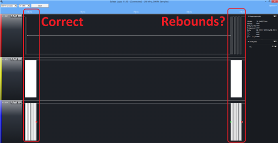
  • i show one I2C transaction, i called each transaction "correct" and "rebound" (because have rebounds on interrupt pin):

    "Correct" zoom:

    "rebound" zoom:

    Both sequences are the same and send/receive correct data ( address, C9, receive some data, address, D9, receive some data, address, F9, receive some data, address, E8, receive some data) but "rebound" would not have to be. (also note that "rebound" interacts with interrupt in a peculiar way: after send write command occurs falling edge , and after read command occurs rising edge )

  • hello again,

    inside inthandler i have this if:

    if(GPIOPinIntStatus(GPIO_PORTE_BASE, false)&(GPIO_PIN_0))
    {
    ...send/receive i2c code..
    }

    and works like another image, with two sequences: "correct" and "rebound".

    if i put if(1), has no "correct", every time is "rebound", every time runs interruption, even when i have not touched the screen anytime.

    So, i think if(GPIOPinIntStatus(GPIO_PORTE_BASE, false)&(GPIO_PIN_0)) is neccessary, but the interruption would not have to run all the time like now. I force I2C interruptions to disable with IntDisable(INT_I2C2); but nothing changes...

    therefore, must be one of these things:
    - Stellaris launch interrupt because i dont know why.
    -TSC2007 causes interrupt because internal architecture.

    I try almost everything modes described on datasheet and nothing changes. (some modes disables interrupt pin, but all modes with interrupt active works launching falling edge each write sequence.

    As I can understand, TSC2007 modes allways launch interrupt (forced low INT pin) so maybe "correct" sequence has no interrupt edges because INT pin is attached to touch panel and forced low when pressed (int edges trying to appear but forced low).

    So: the main problem is why MCU not mask interrupts on interrupt function (MCU do interrupt function, but at finish do again the same interrupt function, maybe because he has kept the interrupt request caused during the function).

    Another meaning was that touch interrupts works well (E0 pin) but another interrupts takes place (another port E pin, like I2C pins). But why? i have not enable another interrupts, only interrupt in E0 pin:

    GPIOPinTypeGPIOInput(GPIO_PORTE_BASE, GPIO_PIN_0);
    GPIO_PIN_TYPE_STD_WPU);
    //Enable interrupt on E0
    IntMasterEnable();
    GPIOIntTypeSet(GPIO_PORTE_BASE, GPIO_PIN_0, GPIO_FALLING_EDGE);//GPIO_FALLING_EDGE GPIO_LOW_LEVEL GPIO_DISCRETE_INT GPIO_RISING_EDGE GPIO_BOTH_EDGES
    GPIOPinIntClear(GPIO_PORTE_BASE, GPIO_PIN_0);

    IntEnable(INT_GPIOE);
    GPIOPinIntEnable(GPIO_PORTE_BASE, GPIO_PIN_0);


  • woh, how many work! 

    I have new findings:

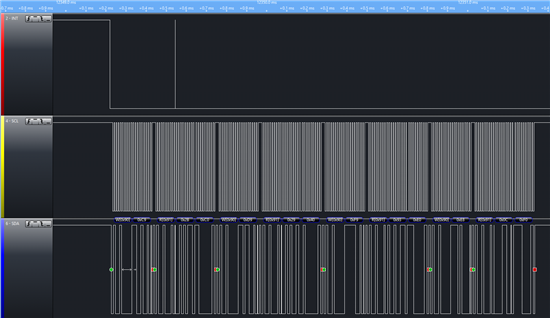
    Now, touch works almost perfect, except when I2C breaks (SDA comes low level and stay here... It ocurrs when quick speed interrupt (rebounds with stylus) i think). I attach one image:

    Interrupt ocurrs only when i press screen (both edges). Then, if E0 is LOW, MCU send 4x I2C messages:
    -Measure X  (1100)+Enable A/D & Disable INT(01)+12bit mode(0)+dont care(0) =C4 
    -Measure Y  (1101)+Enable A/D & Disable INT(01)+12bit mode(0)+dont care(0) =D4
    -Measure Z1 (1110)+Enable A/D & Disable INT(01)+12bit mode(0)+dont care(0) =F4
    -Measure Z2 (1111)+LowPower & Enable INT(00)+12bit mode(0)+dont care(0) =E0
    And later send WidgetPointerMessage(WIDGET_MSG_PTR_DOWN, lx, ly);

    If E0 is HIGH send WidgetPointerMessage(WIDGET_MSG_PTR_UP , lx, ly); (with coordenates from latest measures, not new ones because measures when remove stylus are wrong).

    Now i clear interrupt: GPIOPinIntClear(GPIO_PORTE_BASE, GPIO_PIN_0);

    I have attended to what Dave said, but if i put GPIOPinIntClear before send I2C messages, write to touch driver causes to edge INT pin, so interrupt is set after cleared and later when i enable interrupts, interrupt is called again.

    This is my code:

    On main:

    //******Enable I2C
    SysCtlPeripheralEnable(SYSCTL_PERIPH_GPIOE);
    GPIOPinTypeI2CSCL(GPIO_PORTE_BASE, GPIO_PIN_4); // special I2CSCL treatment for M4F devices
    GPIOPinTypeI2C(GPIO_PORTE_BASE, GPIO_PIN_5);
    GPIOPinConfigure(GPIO_PE4_I2C2SCL);
    GPIOPinConfigure(GPIO_PE5_I2C2SDA);
    SysCtlPeripheralEnable( SYSCTL_PERIPH_I2C2);
    I2CMasterInitExpClk( I2C2_MASTER_BASE, SysCtlClockGet(), false);
    SysCtlDelay(100);
    //*************************************************

    //*******Enable Interrupts on E0

    GPIOPinTypeGPIOInput(GPIO_PORTE_BASE, GPIO_PIN_0);
    GPIO_PIN_TYPE_STD_WPU);
    //Enable interrupt on E0

    GPIOIntTypeSet(GPIO_PORTE_BASE, GPIO_PIN_0, GPIO_BOTH_EDGES);//GPIO_FALLING_EDGE GPIO_LOW_LEVEL GPIO_DISCRETE_INT GPIO_RISING_EDGE GPIO_BOTH_EDGES
    GPIOPinIntClear(GPIO_PORTE_BASE, GPIO_PIN_0);

    IntEnable(INT_GPIOE);
    GPIOPinIntEnable(GPIO_PORTE_BASE, GPIO_PIN_0);
    IntMasterEnable();

    //****************************************************
    GPIOPinIntDisable(GPIO_PORTE_BASE, GPIO_PIN_0);
    LCDBPV2_backlight_init();
    LCDBPV2_touch_Init();
    GPIOPinIntEnable(GPIO_PORTE_BASE, GPIO_PIN_0);

    On touch.c:

    void touch_IntHandler(void) 
    {
    GPIOPinIntDisable(GPIO_PORTE_BASE, GPIO_PIN_0);
    if(!GPIOPinRead(GPIO_PORTE_BASE,GPIO_PIN_0))
    {
    cx2=ReceiveI2C_(0xC4); 
    cx3=ReceiveI2C_(0xD4);
    cx4=ReceiveI2C_(0xf4); 
    cx5=ReceiveI2C_(0xe0); 
    }
    rtouch=((cx3*(cx4-cx5))/(4096*cx5));
    cx2=4095-cx2;
    cx3=4095-cx3;

    //ESCALADO********************
    //Y: cx2:250-3820 --->240 cx2:360-3780 --->240
    if(cx2<YMIN) cx2=YMIN;
    if(cx2>YMAX) cx2=YMAX;
    cx2=(cx2-YMIN); //3430

    //X: cx3:300-3880 --->320 cx3:380-3770 --->320
    if(cx3<XMIN) cx3=XMIN;
    if(cx3>XMAX) cx3=XMAX;
    cx3=(cx3-XMIN);

    //320x240 //3420
    cx2=(cx2*240)/((YMAX-YMIN));
    cx3=(cx3*320)/((XMAX-XMIN));//((XMAX-XMIN)+370);
    //***************************

    if(cx5>100) //usar rtouch en vez de cx5
    {
    xbk=cx3;
    ybk=cx2;
    WidgetPointerMessage(WIDGET_MSG_PTR_DOWN, cx3, cx2);
    }

    else if(GPIOPinRead(GPIO_PORTE_BASE,GPIO_PIN_0)) 
    {
    WidgetPointerMessage(WIDGET_MSG_PTR_UP , xbk, ybk);

    }
    GPIOPinIntClear(GPIO_PORTE_BASE, GPIO_PIN_0);
    SysCtlDelay(100);
    GPIOPinIntEnable(GPIO_PORTE_BASE, GPIO_PIN_0);

    }

    void LCDBPV2_touch_Init()
    {

    I2CMasterSlaveAddrSet( I2C2_MASTER_BASE, 0x48, false);
    //send command byte
    I2CMasterDataPut( I2C2_MASTER_BASE, 0xB0);
    I2CMasterControl( I2C2_MASTER_BASE, I2C_MASTER_CMD_SINGLE_SEND);
    WaitI2CDone( I2C2_MASTER_BASE);

    //dummy read to set low power mode
    ReceiveI2C_(0xc0);

    }

  • Your code looks rather more complex than I would expect and, frankly, I'm very wary of the fact that you need a long SysCtlDelay call in your interrupt handler but, if it's working, I guess that's good.

    The root cause of your problems is almost certainly the fact that your interrupt handler does a lot of very long, time consuming operations and it didn't take into account the fact that another edge may appear on the interrupt pin while the handler was running. Unless you move the long operations out of the interrupt context, the solution of disabling the interrupt in the GPIO module while you process the previous one is likely the way you will have to go. If you were starting this project again, though, I would suggest you do as little in the ISR as possible and move the time-consuming code to another thread or your main loop instead.

    In its current form, you will need to be very sure that you set your interrupt priorities carefully because, with the default settings, this ISR will cause enormous interrupt latency and likely cause other time sensitive interrupts to starve.

  • You're right, this interrupt consumes too much time. I think i have some problem because this, but i need to do to much things and i make complex and dirty code, but I try to clean it when works succeed.

    Now, i have another problem (never ends...): Touch driver causes interrupt by direct LCD touch so waveform has rebounds, mainly at the end. MCU send I2C messages after edge but problems start when there is some rising edge rebound (rising and falling) that causes another I2C message and it dont finish before next rebound.

    I put GPIOPinIntDisable(GPIO_PORTE_BASE, GPIO_PIN_0); and GPIOPinIntEnable(GPIO_PORTE_BASE, GPIO_PIN_0); between interrupt code (also I2C send/receive code), but i think it dont work. i need to do any more to disable interrupts or there is some circumstance that overrides disable request? i include "driverlib/interrupt.h", "driverlib/gpio.h", "inc/hw_ints.h", "inc/hw_gpio.h" and some more.

    For example, If i try GPIOPinIntDisable in main c dont work. If y try inside interrupt function i think sometimes work...

    Check the image: I2C works, but at the end there is some rebound, so as in the begin of the interrupt, MCU writes to address 0x90. This byte is sucessfully send, but then is needed to send command byte and concur with rebound, so send incorrect data. Maybe i should put some capacitor to attempt to avoid rebounds, but first i like to know if there is some software way. For example, delay at the beginning of the interrupt forces to whait some time and later checks if pin stays low. If not, there is a rebound so I can obviate them.

  • If you want to be sure that you don't get interrupts from GPIO Port E, pin 0, GPIOPinIntDisable(GPIO_PORTE_BASE, GPIO_PIN_0) is the right thing to do. If other pin interrupts on Port E are still enabled, you'll still get calls to the Port E interrupt handler but GPIOPinIntStatus() will show you which pins interrupted and pin 0 won't be one of them.

    The problem here seems to me that you need to debounce the GPIO signal. There are various ways to do this but I would likely start by using a timer to reenable the GPIO interrupt after some period of time. When you get an interrupt, disable the pin interrupt and process it as normal. When you've finished, start the timer. When the timer interrupts, re-enable the GPIO interrupt again. The timer period will have to be determined by the maximum frequency you want to process touch messages (perhaps 100 a second or so?) and also the time period during which you are seeing bounces on the GPIO line (which you should be able to determine using your logic analyzer).

    There are other ways to debounce the signal involving reading it multiple times and only acting when you've read it in the same state a certain number of times. I think we even do something like this in the existing resistive touch panel drivers. They will all likely involve timers and interrupts, though, so I would start with the simple approach I outlined and see if that works. Perhaps other readers can offer better suggestions?

  • I have reduced interrupt function to this:

    void touch_IntHandler(void)
    {

      GPIOPinIntClear(GPIO_PORTE_BASE, GPIO_PIN_0);
      if(!GPIOPinRead(GPIO_PORTE_BASE,GPIO_PIN_0))
      {

        touchstate=1; //1=down
      }

      else if(GPIOPinRead(GPIO_PORTE_BASE,GPIO_PIN_0))
      {

        touchstate=2; //2=high
      }

      fl=0;
      GPIOPinIntEnable(GPIO_PORTE_BASE, GPIO_PIN_0);
    }

    And seems to work well with parallel mode on LCD but not in serial (parallel fastest than serial and, in any case in serial mode, a command can be half sent if an interrupt comes between it).
    So I put disable/enable between draw function (I also put this into primitive functions in driver library: draw pixel, draw line...) :

    GPIOPinIntDisable(GPIO_PORTE_BASE, GPIO_PIN_0);
    GrCircleFill(&sContext, cx3,cx2,size);
    GPIOPinIntEnable(GPIO_PORTE_BASE, GPIO_PIN_0);

    But MCU breaks (in serial mode). I try to look it with logic analyzer and, at first touch, circle on the screen is drawn, and sometimes at second touch, but later nothing more is drawn on the screen. But touch driver remain his comunication with MCU some time more (send and receive) and later I2C breaks also (SDA remains at low level).

    So, again, i think that GPIOPinIntEnable/Disable wont work as expected (maybe i am wrong).

    I just implement timer interrupts to force read when low state of the gpio pin (besides edges), I use paint example so i try to explain with this:
    -When falling edge, there is only one I2C data request, one pixel paint on screen.
    -After falling edge, a flag was set and timer interrupt is enabled. This timer interrupt send I2C data request every interrupt bounce. The result is that I can draw how moving through the screen.
    -Rising edge disables timer interrupt.

    With more tan 150us between end of I2C stream (all sequence that before was in the interrupt) and start of the next I2C stream works without reenter at the interrupt, but if i set less than 150us it reenter at the interrupt.

    So, timer interrupt limits the number of reads per second.

    Tomorrow i will try to check if now is necessary to implement Dave's idea with timers (maybe i can use the same timer).

    At the moment, parallel LCD seems to work without any problem, serial has some problems randomly (after a time):
    -I2C breacks 
    -LCD breacks (send incorrect command and screens power off, or turns around, or shifts xy coordenates or some other command)

  • Another (maybe simpler) way to do this is to use the SysTickIntHandler to poll the INT pin of the touch ic. You can use the ButtonsPoll() function from buttons.c driver from TivaWare examples to do the debouncing of the INT pin.

    While INT pin is low,  the touch screen is in pressed state, so in this way you can detect presses, releases, autorepeats or movements.

    tibcsi

  • I will think about this.

    As I said before, i have problems whith serial mode (LCD), not on parallel at the moment. I think is because some interrupt stops or stutters data transmission, but I'm not sure. 
    I think that one solution will be to put enable/disable of each interrupt i made GPIOPinIntDisable() (I try putting global IntMasterEnable() / disable but I think it not let interruptions as before, is needed to to re-activate all one by one).

    But maybe this solution skip some interrupt if occurs exactly when LCD write, so I think about créate a "software" interrupt. This is posible? My idea is to throw an interrupt when there is a LCD write  to avoid being masked by another interrupt. In this way, incoming interrupt would need to wait to finish writing the LCD.

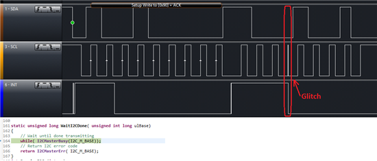
    I attach a image of one glitch:

  • You may want to look into interrupt priorities. By default, all the interrupts have the same priority so no ISR will ever be interrupted. You can, however, change the priorities so that a lower priority ISR can be interrupted by a higher priority one. Correct priority setting may help you get round some of the problems you are facing.

  • Dave Wilson said:

    You may want to look into interrupt priorities. By default, all the interrupts have the same priority so no ISR will ever be interrupted. You can, however, change the priorities so that a lower priority ISR can be interrupted by a higher priority one. Correct priority setting may help you get round some of the problems you are facing.

    But LCD does not throw any interrupt. How i do to throw an interrupt with LCD? or set interrupt like priority to one function.

    I would like something like: 

    -call some function to launch interrupt
    -[code]

    every LCD function

  • About I2C glitch:

    Sometimes when coincides falling edge of interrupt and I2C comunication, SDA  makes a pulse. This corrupts the communication and MCU remains on "while( I2CMasterBusy(I2C_M_BASE));".

    I try to solve this with another timer more or something.

    You think this is hardware problem (because I use poor wiring with normal dupont cables with this alignment: INT, SCL, SDA, GND. Maybe It would be better if I transport INT into a separated cable twisted with GND) or could be any software problem?.

  • Hi Daniel,

    If the issue is really of a glitch on the I2C Line due INT rebounce, then you can the glitch filter on I2C to weed out smaller runt pulses.

    I am not sure which device you are using. TM4C123 or TM4C129, so would put the data for both

    1. TM4C123: I2CMCR2.GFPW register.bit-field for selecting the glitch pulse width to filter out and I2CMCR.GFE register.bit-field to enable the feature.

    2. TM4C129: I2CMTPR.PULSEL for selecting and enabling the glitch pulse width.

    The glitch filter is in terms of system clock. Hence if the system clock is say 40MHz (25ns), and the filter width is set to 1 clock then a glitch of up to 25ns will be filtered out. Do make sure that the Pulse Width setting is not so large that the SCL or SDA valid pulse is filtered.

    Secondly, if you are running free wiring, then cross talk can be a problem. Ground Shielding would be useful.

    Thirdly, looking at the waveform, the Setup Write has 9 SCL pulses, but the next I2C transaction has 8 (including the glitch) SCL pulses. This is strange as it is a Master Write, the I2C should have generated 9 SCL pulses (8 for data and 1 for ACK/NACK)

    Regards

    Amit

  • Amit Ashara said:

    Hi Daniel,

    If the issue is really of a glitch on the I2C Line due INT rebounce, then you can the glitch filter on I2C to weed out smaller runt pulses.

    I am not sure which device you are using. TM4C123 or TM4C129, so would put the data for both

    1. TM4C123: I2CMCR2.GFPW register.bit-field for selecting the glitch pulse width to filter out and I2CMCR.GFE register.bit-field to enable the feature.

    2. TM4C129: I2CMTPR.PULSEL for selecting and enabling the glitch pulse width.

    The glitch filter is in terms of system clock. Hence if the system clock is say 40MHz (25ns), and the filter width is set to 1 clock then a glitch of up to 25ns will be filtered out. Do make sure that the Pulse Width setting is not so large that the SCL or SDA valid pulse is filtered.

    Secondly, if you are running free wiring, then cross talk can be a problem. Ground Shielding would be useful.

    Thirdly, looking at the waveform, the Setup Write has 9 SCL pulses, but the next I2C transaction has 8 (including the glitch) SCL pulses. This is strange as it is a Master Write, the I2C should have generated 9 SCL pulses (8 for data and 1 for ACK/NACK)

    Regards

    Amit

    oh thanx for your reply!.

    I'm not using any of them. I'm using stellaris launchpad LM4F120H5QR (I port this to tiva when when run well on stellaris).

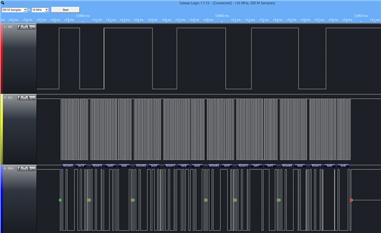
    The last problem you said, I am thinking is because INT pin. Would have to be a clock pulse when INT goes high (after 9 pulse), but there isn't, SCL remains low.

    I attach a picture to show this. In this picture there isn't any glitch, but lack a pulse after 7 SCLK pulse, when INT goes high.

    Im trying to do watchdog like for I2C with one timer to force retrasmission of the data if sda remains low (attempting to receive something)).

    MCU keeps working but without I2C. How i can restart I2C? I try with the same configure commands but seems to send nothing, I2C is break. 

  • Hi Danielle,

    On LM4F120, the Glitch Filter will not work for sure.

    If I2C Master is hung, then you will have to reset the I2C Master to restart I2C.

    Also on the I2C Line what is the strength of Pull Up connected? I checked the TSC2007 data sheet as well to make some sense of why an interrupt from the touch controller could make the SCL become glitchy, especially on the rising edge, and it seems for the moment it is to do the following

    1. Improve cable shielding for SCL, SDA and INT.

    2. Decrease the Pull Up Resistor Strength.

    Lastly, the scope plot you have is a logical analyzer, can you connect a Scope Probe to help us profile the type of Glitch?

    Regards

    Amit

  • Amit Ashara said:

    If I2C Master is hung, then you will have to reset the I2C Master to restart I2C.

    I try with SysCtlPeripheralDisable( SYSCTL_PERIPH_I2C2); and later enable but seems to not work. Also I2CMasterInitExpClk( I2C2_MASTER_BASE, SysCtlClockGet(), false); 

     You said another function?

    Amit Ashara said:

    Also on the I2C Line what is the strength of Pull Up connected? 

    Uhm.. if i need to change I2C resistors would be a problem because i send some boosterpacks. But if this solve the problem, it is the best.

    I have 10k pull up resistors. Maybe too high? I usually put 4k7 but i dont remember why I put 10k. I use these values for 5v pullup but for 3.3 could be a problem. I must try with 4k7?.

    Amit Ashara said:

    1. Improve cable shielding for SCL, SDA and INT.

    I change INT to a separate cable with ground (not coaxial nor shielded, both cables in parallel) and seems to be the same. I need to try with more cables.

    Amit Ashara said:

    Lastly, the scope plot you have is a logical analyzer, can you connect a Scope Probe to help us profile the type of Glitch?

    Is complicated because my scope has not too many memory to store too much samples and later found the glitch, but I will try it.

    These are some captures I was here from before

  • I changed I2C pull up resistors to 1K (3'3mA) and, at the moment, seems to work perfect without rebounds.
    What resistor values you recomend? maybe 3'3mA per wire is too high (6'6mA...), what you think?
    Check 7.1 point of I2C specification article: http://www.nxp.com/documents/user_manual/UM10204.pdf and recommends even lower vaules, but maybe dont consider "low power"/portable devices for this. Also, maybe newer chips and microcontrollers are capable to work with higher values than shown in the specification.

    I'm trying to find wrong I2C data but at the moment there isn't.

    This is one good I2C data transmission, when one INT pulse:

    I'm going to oscilloscope to check the aspect of the signals.

  • Hello Daniel,

    The TSC2007 data sheet shows 1.2K Pull Up resistor (which works about 5.5mA). I cannot suggest a value as it seems power in your case is important. You would have to check the highest resistor which allows the application to work.

    Also the function to reset the peripheral is SysCtlPeripheralReset.

    Regards

    Amit

  • Amit Ashara said:

    You would have to check the highest resistor which allows the application to work.

    How? verifiing with oscilloscope that is not deformed? Now with 1K seems to work very well.

    Amit Ashara said:

    Also the function to reset the peripheral is SysCtlPeripheralReset.

    Thanx!! I think it is no longer necessary, (I2C breaks seems to dissapear) but I'm going to write down to remember it when I need.

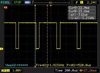
    --------------------------------------------------------------

    I have some waveforms to show!

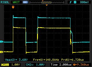
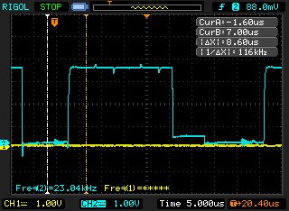
    This is SCL now, seems to be some little offset but works.

    This is SDA:

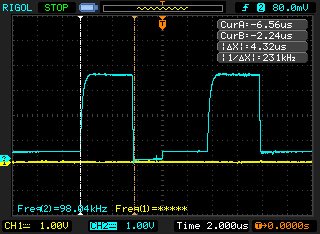
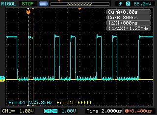
    This is CS from LCD bus:

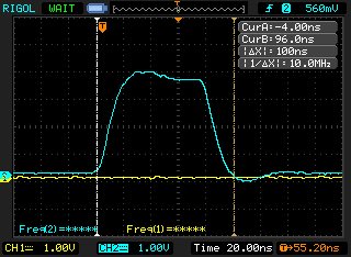
    This is CLK from LCD bus:

    As you see, CLK is pretty bad. So I check code configuration and I change 

    GPIOPadConfigSet(GPIO_PORTC_BASE,GPIO_PIN_4|GPIO_PIN_5|GPIO_PIN_6|GPIO_PIN_7, GPIO_STRENGTH_2MA,GPIO_PIN_TYPE_STD);

    for:

    GPIOPadConfigSet(GPIO_PORTC_BASE,GPIO_PIN_4|GPIO_PIN_5|GPIO_PIN_6|GPIO_PIN_7, GPIO_STRENGTH_8MA_SC,GPIO_PIN_TYPE_STD);

    and this is my new waveform:

    Maybe this solves some problems but the LCD still receiving erroneous commands (rarely, but sometime).

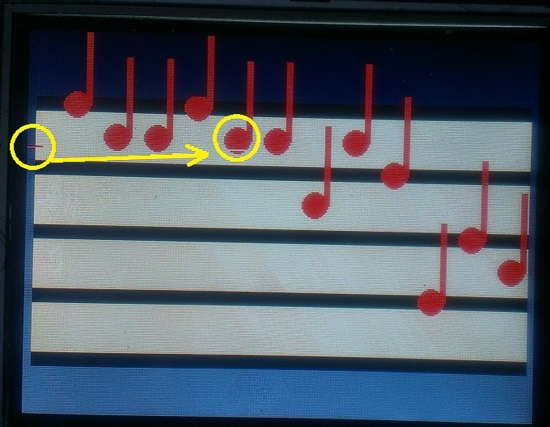
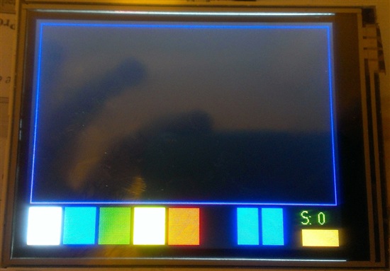
    This is normal screen:

    and this is screen after bad commands (only happens (rarely) when I touch the screen (and draw). I'm not sure if it is after a time or is totally random):

  • Hi Daniel,

    SCL and SDA for higher Pull Up Resistor will always follow the "Shark-Fin" pattern. You can increase the Pull Up strength to the point the INT foes not cause clock to be missing or clipped.

    Good to hear that the I2C is now working. It could be possible that the TSC2007 may be causing the runt pulses to appear. It would be a good forum post for TSC2007 to answer that if you do want to know why this would be the case.

    Regards

    Amit