This thread has been locked.

If you have a related question, please click the "Ask a related question" button in the top right corner. The newly created question will be automatically linked to this question.

TM4123GH6PGE USB device not recognized

Other Parts Discussed in Thread: TM4C123GH6PGE

Hello,


I have been developing a USB bulk device application for the TM4123GH6PGE.  I have been using the LM4F232H5QD Evaluation board and we have recently had a prototype board made for our device using the TM4123GH6PGE.  The problem is that when I run the application on the prototype, windows does not recognize the USB device and creates an unknown device with error code 43.


When I look at the properties of the device in windows, the hardware and vendor ids are both zero.  I do know that when the bootloader runs the DFU device does appear correctly in windows and flash programming can be completed without issue.  If my device attempts to switch to DFU mode, that does not work either and the same unknown device appears in windows.  I can get the DFU device to be recognized by windows by erasing flash which forces the bootloader to run.


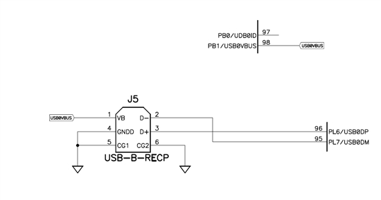
The main difference in the hardware for our design is we are using the standard USB cable with a 6-pin B side, as opposed to the micro-B connector used on the eval board.  The connector has no direct connection to PB0 USB0ID because we are not attempting to use OTG mode, and the documentation implies that when set as a device, this pin can be left floating.  Pins 4,  5, and 6 are grounded, pin 1 is connected directly to VBUS, pin2 to USB0DM, and pin3 to USB0DP.


I am having difficulty determining why I cannot run the same code that runs on the eval board on the prototype board.  I believe the design of the board is correct because the DFU device works exactly as it should when started by the bootloader.  Any help would be greatly appreciated. 


Jon


  • Does the LM4F232 support OTG? If not, maybe you are running into this issue:

    http://processors.wiki.ti.com/index.php/Tiva_C_USB_Mode_Force_Device

  • Yes.  The LM4F232 / TM4C123GH6PGE supports OTG mode, but I would still like to force device mode.  The function referenced in the link is USBStackModeSet(), this function is not used by the bulk device examples, only the serial device examples.  I am developing a self powered bulk device with VBUS monitoring.  It is the USB0ID pin that is not connected.  I am still unable to connect the real device, only the eval board.

  • Hello Jon,

    Would you please provide the schematic of the USB section of your board for a quick review? 

    Would you please also perform the steps 1 through 4 listed here (http://technet.microsoft.com/en-us/library/cc725873(v=ws.10).aspx) and let me know if that solves the problem?

  • Ashish,

    I attached the schematic you requested.  Also, I attempted the steps 1-4 mentioned in the link and the problem remains the same.

    Jon

  • Additional information determined by running the debugger on both:

    On the Eval board USB interrupts are seen for Reset, and Suspend, and Set Address.  On the prototype board, Reset and Suspend interrupts occur and nothing after that.  There is no Set Address from the host.

  • Hi Jon,

    Thanks for your patience and providing the schematic. The USB0ID pin of the micro USB connector on the eval. board is connected to the USB0ID pin of the USB controller. The ROM based USB boot loader ignores the status of USB0ID pin. As a result, DFU device is getting recognized by Windows on both the boards i.e. evaluation kit and your custom board.

    However, the usb_bulk_device example does not do that. So, if the USB0ID is left not connected, one needs to force the USB controller in device mode. In order to do that in the usb_bulk_device example, please locate the following statement, and change it to the following. Please rebuild the code, program the MCU on your custom board and that should solve this problem.

    Change from:
    // Initialize the USB stack for device mode.
    //
    USBStackModeSet(0, eUSBModeDevice, 0);

    Change to:
    // Initialize the USB stack for device mode.
    //
    USBStackModeSet(0, eUSBModeForceDevice, 0);

  • Ashish,

    The suggestion you made has already been suggested by Stepman in the post dated 1/10/14.  The link provided is identical to your suggestion.  I have tried using the USBStackModeSet() function call and it did nothing to change the situation.

  • Jon,

    You mentioned that on the eval. board USB interrupts are seen for Reset, and Suspend, and Set Address. On the custom board, Reset and Suspend interrupts occur and nothing after that. There is no Set Address from the host.

    The Reset & Suspend do not involve communication with the host, and interrupts for these events will occur even if the clock to USB controller is not exact. However, for Set Address interrupt to occur, communication between host and device is required. The fact that its not happening on custom board is a sign that possibly the USB clock may not be correct. You mentioned that you are using the example as is. The example was written for EK-LM4F232 board which uses a 16MHz. Does your board also have a 16MHz crystal? Can you please check if the crystal & caps are properly connected on your board?

  • Ashish,

    You are correct.  On our board we are using a 20 MHz crystal.  I changed the call to ROM_SysCtlClockSet() to use the constant SYSCTL_XTAL_20MHZ and the board is now recognized.  Thank you for resolving this issue!

    Jon

  • Jon,

    That's great to know, thanks for letting me know. I appreciate your patience!