This thread has been locked.

If you have a related question, please click the "Ask a related question" button in the top right corner. The newly created question will be automatically linked to this question.

Initial programming of TM4C123FH6PM via UART

Other Parts Discussed in Thread: MAX3232, MAX232

Hello All,

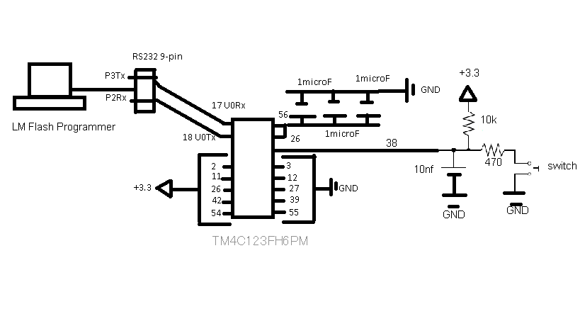
I have been hacking away at the datasheet, rom bootloader datasheet and forum and cannot find a definitive answer to this question.  I am designing a custom board and in a cost-saving effort, it does not have an external oscillator.  I would like to program the board using the LM Flash Programmer via UART or USB using the ROM bootloader.  According to the datasheet and forum posts, it appears that programming via USB is out of the question as it needs a main oscillator (external) to provide the clock source and cannot use the precision internal 16Mhz oscillator for this purpose.


Additionally, the datasheet states that by default, UART and SSI use the main oscillator (external) as their clock source and consequently leads me to believe that an external oscillator is also required for initial device programming via the ROM bootloader using UART, as is the case with the USB approach.


Initial device programming via the ROM bootloader is seen as a cost saving measure; do I need to install an external crystal oscillator to use it?


Thanks.

  • For the UART and SSI peripherals, the default clock is the "system" clock.  Alternatively, these peripherals may be configured to use PIOSC directly, independent of what the "system" clock is.  In the boot loader, the configuration for the clocking of these peripherals is not modified and remains as the "system" clock.

    The "system" clock in a TM4C123 class device defaults to being the PIOSC.  There are a number of alternate configurations that may be programmed, including the use of an external crystal, the internal PLL and various combinations.  However, for the boot loader, the "system" clock remains as the PIOSC and is not reconfigured.

    The USB peripheral requires the use of an external crystal.  In the boot loader, the presence of this crystal is detected, and if it is found, the main oscillator using the external crystal will be enabled, and the USB peripheral will be configured to use this clock source.  However, this will not alter the setting of the "system" clock ... it remains configured as PIOSC, and the UART and SSI peripherals will be clocked from this source.

    Summarizing all of this, it is not necessary for you to have an external crystal to use the UART or SSI boot loader on the TM4C123 class device.

    --Bobby

  • Thank you for this information, it is much appreciated.  I made a total of four boards with the schematics below, as it is evident, it is a design made as simple as possible.  When power was applied to the board and a connection using the LM Flash Programmer was used, I received an error stating: "Failed to establish communication with the board...."  Under the interface box in the LM Flash Programmer Program tab, Serial(UART) was selected the baud rate was 115200 (tried 9600 as well), transfer size was set to 60 and tried with the Disable Auto Baud Support check box checked and unchecked to no avail.  I tried resetting the board using the information found on the datasheet (with an external switch as indicated in the schematic), also to no avail.

    The capacitors used are ceramic with inherent low ESR.  When I left power applied to the chip, the current slowly climbed from 0.06A (@3.0VDC) to over 1A (@3.3VDC) for a period of 30-60 mins (I switched from 3.0VDC supplied to the first board to 3.3VDC to the rest of the boards); during this time I took voltage readings from pins 56 and 25 (LDO voltage supply to the core if I am not mistaken) and it ranged from 0.02V to 1.32V (this reading was not linear and appeared to stabilize at 1.32V for an extended period of time before dropping to 0.02V +-.05V as the amperage reached ~1A+).  Most chips reached a very high temperature and I figured something had gone wrong since the chip is only supposed to consume 58.7mA under full load.


    Before building an exact replica to the DEV board (capacitors, etc...) I would like to know if there is anything that stands out as being the source of the problem.  Thanks again for your help.

  • Hello,

    I've forwarded this information to some of the people in our hardware team.  I hope to have some information for you later today.

    --Bobby

  • Hello,

    I've spoken with someone on our hardware team.  After looking through your posts, they have the following questions:

    1. Does the current increase only occur when the hooked to the PC with the LM Flash programmer?
    2. Does he have a transceiver between the TM4C129 RX/TX pins and the 9 pin connector?  If not this is his problem as he is pumping in +/- 15V on those two pins and causing latchup
    3. What is the source of the 3.3V supply?

    --Bobby

  • Come to think of it, yes, the current consumption increased when I plugged it into the RS232 Tx/Rx pins, I will need to make another board to be sure.  I just checked the voltage coming out of the pin 3 (Tx) on the serial connector and it reads 6.32V.  The transceiver that I am using is a converter from USB to RS232 9-pin model UR-2000M2 from QVS.


    The power supply used is a lab adjustable type made by HQ Power, model PS3003U with no observable ripple voltage at 3.3VDC (tolerance of 0.01VDC).

    What should the voltage be coming to the chip?

    Thanks.

  • Ivan,

    You have two problems with your design.

    1) VDDC needs filtering capacitors of between 2.5 µF to 4.0 µF located close to pin 56 and also connected to pin 25. A mix of high and low values should be used (2.2 µF and 0.1 µF should do for your low cost application, but an additional 1 µF and 0.01 µF is better). VDDC is the LDO voltage regulators output, which requires externally provided filterign capaciotrs to do its job of providing the core's 1.2 V source.

    2) You cannot connect RS232 directly to the microcontroller. RS232 has well over ±5 V swings which is beyond the microcontroller's specification. The microcontroller's internal clamping diodes would start conducting and large amounts of current will be drawn. You will need to include something like a MAX3232 chip (and its associated 4 x 0.1 µF capacitors) to provide the required level translations. Given that you are going for a low cost solution, the MAX3232 chip could be built once and be outside the product (but then your product would not have an RS232 interface). If you do this, you may want to change the connector type to stop someone inadvertently plugging in an RS232 connectionYou should also include ~100 Ω resistors to any lines that go to the outside world to provide protection (the 100 Ω in combination with the microcontrollers internal protection diodes will limit the fault current).

    While I've got you, if you are looking for a minimum cost solution you can remove the 470 Ω resistor and 10 nF capacitor from the circuit and everything will still work fine.

    Regards, Vito

  • Ivan,

    Rather than converting USB to RS232 then to 3.3 V logic levels, you may want to consider a USB to 3.3 V logic level converter. For example take a look at http://www.ftdichip.com/Products/Cables/USBTTLSerial.htm and the TTL-232R-3V3 (~$25) or TTL-232R-3V3 (~$22). I'm sure there are cheaper suppliers out there.

    Regards, Vito

  • Thanks Vito for the helpful insight.  The 3.3V USB to UART cable should be coming in and I'll give it a test once it does.  I'll also modify the filtering capacitance setup as well when I make the new board.  Thanks again and I'll revert with the outcome.

  • I think i am missing something or please someone guide me.....

    Can we do that?? my first question. I mean to imply dont we need any hardware in between ??

    For example j link or XDS-100. If i am not missing anything then LM flash programmer software is directly connected to controller board through serial port (via MAX232), and we can directly program the controller??

    Thanks.

  • mayank kumar shukla said:
    If i am not missing anything then LM flash programmer software is directly connected to controller board through serial port (via MAX232), and we can directly program the controller??

    I have not done that. But, there is an option at LM Flash Programmer to set the interface to "Serial (UART)".

    - kel