This thread has been locked.

If you have a related question, please click the "Ask a related question" button in the top right corner. The newly created question will be automatically linked to this question.

Serial Transmission and DAC using Tiva launchpad (TM4C123GH6PM)

Other Parts Discussed in Thread: TM4C123GH6PM, EK-TM4C123GXL

Hello,

I am using TM4c123GH6PM launchpad of TIVA and want to transmit data serially using the launchpad.
Currently I have completed the interface of Keypad and ADC. Now would like to integrate DAC and SSI for digital data transmission.

Can anyone help me with the programming. I have only one launchpad working and would like to check the transmission and reception using the same launchpad. Can it be done.

Kindly guide.

Thank you.

Sincerely,
Mit Morbia

  • Hi Mit,

        You can try the uart_echo example program. That can be found at "\examples\boards\ek-tm4c123gxl\uart_echo". 

    -kel

  • Hi Mit,

    The SPI peripheral can be used in LoopBack Mode. There is an example in the examples -> peripherals -> ssi -> spi_master.c that you can use as a reference to initialize SPI and send-recieve data,

    Regards

    Amit

  • Hey Amit,

    This helped me a lot bro. But how do i simulate it and check the data. Will I have to copy the data in one of the ports or can I read the Rx data directly. Do I need to install any plugin to check the data transmitted.? 

    And do you have any idea about the DAC using PWM? How can i implement those using only a launchpad and also check. Kindly reply.

    Sincerely,

    Mit 

  • Hello Kel,

    Should I use UART or SSI for duplex communication. Need your help. Thank you.

    Sincerely,

    Mit

  • @Mit,

    Your first post is a little bit unclear whether you want to transmit using UART or SSI.

    Deciding whether to use UART or SSI for duplex communication, depends on your application.

    An example of use of SSI interface is for communicating with an SD Card. SSI can provide faster data transfer/rate that is suitable for bulk data transfer such as reading and writing of files in a SD card.

    UART are usually use in compliance with standards of RS-232. RS-485, and RS-422. These standards allow to connect slave device(s) to host device at a longer cable length. Some application for UART are time and attendance systems, and door access systems.

    I suggest that you research the details regarding SSI and UART in the internet.

    For the other readers, It would be great if you provide more details about the project that you are doing.

    -kel

  • Hi Mit,

    You need to compile the example and load it into the design and read the Rx data. The test example reads it into a buffer and prints it on the UART.

    Regards

    Amit

  • @Amit - I loaded it into the CCS and debugged it. I can see the changes in Rx nd Tx variables but they dont match. I mean the data in Tx and Rx should be the same, right.?

    @kel - I want to transmit and receive voice via serial transmission, The flow of the process is as follows .

    Speech Signal > ADC> Transmission > DAC > Amplifier > Speaker.

    From your example I think UART is of my use. I am not aware about the use and programming of UARt. I need help in programming of DAC and UART. The sample program UART polled was tried but I my Tx and Rx output did not match. Also where can I get to see the printf results in CCs V5.5.

    Do you have any sample code for DAC using PWM and UART for continuous two way communication without polling. Thanks. 

    Sorry to ask such stupid questions but I am new to CCS as well to TIVA.  

    Sincerely,

    Mit

  • Hi Mit,

    What is the RX variable after the code run looking like. Can you please send the UART log file as well

    Regards

    Amit Ashara

  • Hi Amit,

    Kindly find the results of SPI program. Let me know the errors you find. 

    4452.SNAPSHOTS OF SSI.docx

    This is error shown in UART.

    Thank you for your kind concern.

    Regards,

    Mit Morbia

  • Hi Mit,

    Is this a SPI Example code or a UART example code? Can you please point me to which example you are referring

    Regards

    Amit

  • Hi Amit,

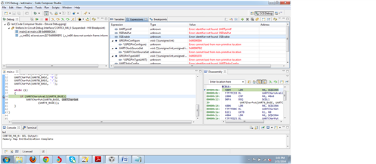
    The doc file attached is the SPI example's output and the image shown is of UART.

    How to get rid of the error *.out file not created which sometimes troubles me alot.

    Thank you.

    Regards,

    Mit Morbia

  • Hi Mit,

        Post your code here or attach your project files, so others can review it.

    -kel

  • Hi Kel,


    I made some amendments in the previous files and was able to see the Tx data transmitted. The main.c file of my project is attached herewith.

    Kindly let me know what changes should I do if i need to transmit the digital data to another TIVA launchpad and receive from there simultaneously. I think I should rather use UART and hence working on that.

    Kindly help me in programming the same as I am a novice. :(

    Thank you.

    sincerely,

    Mit Morbia

    #include <stdbool.h>
    #include <stdint.h>
    #include "inc/hw_memmap.h"
    #include "driverlib/gpio.h"
    #include "driverlib/pin_map.h"
    #include "driverlib/ssi.h"
    #include "driverlib/sysctl.h"
    #include "driverlib/uart.h"
    #include "utils/uartstdio.h"
    
    //*****************************************************************************
    //
    //! \addtogroup ssi_examples_list
    //! <h1>SPI Master (spi_master)</h1>
    //!
    //! This example shows how to configure the SSI0 as SPI Master.  The code will
    //! send three characters on the master Tx then polls the receive FIFO until
    //! 3 characters are received on the master Rx.
    //!
    //! This example uses the following peripherals and I/O signals.  You must
    //! review these and change as needed for your own board:
    //! - SSI0 peripheral
    //! - GPIO Port A peripheral (for SSI0 pins)
    //! - SSI0Clk - PA2
    //! - SSI0Fss - PA3
    //! - SSI0Rx  - PA4
    //! - SSI0Tx  - PA5
    //!
    //! The following UART signals are configured only for displaying console
    //! messages for this example.  These are not required for operation of SSI0.
    //! - UART0 peripheral
    //! - GPIO Port A peripheral (for UART0 pins)
    //! - UART0RX - PA0
    //! - UART0TX - PA1
    //!
    //! This example uses the following interrupt handlers.  To use this example
    //! in your own application you must add these interrupt handlers to your
    //! vector table.
    //! - None.
    //
    //*****************************************************************************
    
    //*****************************************************************************
    //
    // Number of bytes to send and receive.
    //
    //*****************************************************************************
    #define NUM_SSI_DATA            3
    
    //*****************************************************************************
    //
    // This function sets up UART0 to be used for a console to display information
    // as the example is running.
    //
    //*****************************************************************************
    void
    InitConsole(void)
    {
        //
        // Enable GPIO port A which is used for UART0 pins.
        // TODO: change this to whichever GPIO port you are using.
        //
        SysCtlPeripheralEnable(SYSCTL_PERIPH_GPIOA);
    
        //
        // Configure the pin muxing for UART0 functions on port A0 and A1.
        // This step is not necessary if your part does not support pin muxing.
        // TODO: change this to select the port/pin you are using.
        //
        GPIOPinConfigure(GPIO_PA0_U0RX);
        GPIOPinConfigure(GPIO_PA1_U0TX);
    
        //
        // Enable UART0 so that we can configure the clock.
        //
        SysCtlPeripheralEnable(SYSCTL_PERIPH_UART0);
    
        //
        // Use the internal 16MHz oscillator as the UART clock source.
        //
        UARTClockSourceSet(UART0_BASE, UART_CLOCK_PIOSC);
    
        //
        // Select the alternate (UART) function for these pins.
        // TODO: change this to select the port/pin you are using.
        //
        GPIOPinTypeUART(GPIO_PORTA_BASE, GPIO_PIN_0 | GPIO_PIN_1);
    
        //
        // Initialize the UART for console I/O.
        //
        UARTStdioConfig(0, 115200, 16000000);
    }
    
    //*****************************************************************************
    //
    // Configure SSI0 in master Freescale (SPI) mode.  This example will send out
    // 3 bytes of data, then wait for 3 bytes of data to come in.  This will all be
    // done using the polling method.
    //
    //*****************************************************************************
    int
    main(void)
    {
        uint32_t pui32DataTx[NUM_SSI_DATA];
        uint32_t pui32DataRx[NUM_SSI_DATA];
        uint32_t ui32Index;
    
        //
        // Set the clocking to run directly from the external crystal/oscillator.
        // TODO: The SYSCTL_XTAL_ value must be changed to match the value of the
        // crystal on your board.
        //
        SysCtlClockSet(SYSCTL_SYSDIV_1 | SYSCTL_USE_OSC | SYSCTL_OSC_MAIN |
                       SYSCTL_XTAL_16MHZ);
    
        //
        // Set up the serial console to use for displaying messages.  This is
        // just for this example program and is not needed for SSI operation.
        //
        InitConsole();
    
        //
        // Display the setup on the console.
        //
        UARTprintf("SSI ->\n");
        UARTprintf("  Mode: SPI\n");
        UARTprintf("  Data: 8-bit\n\n");
    
        //
        // The SSI0 peripheral must be enabled for use.
        //
        SysCtlPeripheralEnable(SYSCTL_PERIPH_SSI0);
    
        //
        // For this example SSI0 is used with PortA[5:2].  The actual port and pins
        // used may be different on your part, consult the data sheet for more
        // information.  GPIO port A needs to be enabled so these pins can be used.
        // TODO: change this to whichever GPIO port you are using.
        //
        SysCtlPeripheralEnable(SYSCTL_PERIPH_GPIOA);
    
        //
        // Configure the pin muxing for SSI0 functions on port A2, A3, A4, and A5.
        // This step is not necessary if your part does not support pin muxing.
        // TODO: change this to select the port/pin you are using.
        //
        GPIOPinConfigure(GPIO_PA2_SSI0CLK);
        GPIOPinConfigure(GPIO_PA3_SSI0FSS);
        GPIOPinConfigure(GPIO_PA4_SSI0RX);
        GPIOPinConfigure(GPIO_PA5_SSI0TX);
    
        //
        // Configure the GPIO settings for the SSI pins.  This function also gives
        // control of these pins to the SSI hardware.  Consult the data sheet to
        // see which functions are allocated per pin.
        // The pins are assigned as follows:
        //      PA5 - SSI0Tx
        //      PA4 - SSI0Rx
        //      PA3 - SSI0Fss
        //      PA2 - SSI0CLK
        // TODO: change this to select the port/pin you are using.
        //
        GPIOPinTypeSSI(GPIO_PORTA_BASE, GPIO_PIN_5 | GPIO_PIN_4 | GPIO_PIN_3 |
                       GPIO_PIN_2);
        SysCtlPeripheralEnable(SYSCTL_PERIPH_GPIOF);
    
        	// Configure pin 1 as output
        GPIOPinTypeGPIOOutput(GPIO_PORTF_BASE, GPIO_PIN_1);
    
    
        //
        // Configure and enable the SSI port for SPI master mode.  Use SSI0,
        // system clock supply, idle clock level low and active low clock in
        // freescale SPI mode, master mode, 1MHz SSI frequency, and 8-bit data.
        // For SPI mode, you can set the polarity of the SSI clock when the SSI
        // unit is idle.  You can also configure what clock edge you want to
        // capture data on.  Please reference the datasheet for more information on
        // the different SPI modes.
        //
        SSIConfigSetExpClk(SSI0_BASE, SysCtlClockGet(), SSI_FRF_MOTO_MODE_0,
                           SSI_MODE_MASTER, 1000000, 8);
    
        //
        // Enable the SSI0 module.
        //
        SSIEnable(SSI0_BASE);
    
        //
        // Read any residual data from the SSI port.  This makes sure the receive
        // FIFOs are empty, so we don't read any unwanted junk.  This is done here
        // because the SPI SSI mode is full-duplex, which allows you to send and
        // receive at the same time.  The SSIDataGetNonBlocking function returns
        // "true" when data was returned, and "false" when no data was returned.
        // The "non-blocking" function checks if there is any data in the receive
        // FIFO and does not "hang" if there isn't.
        //
        while(SSIDataGetNonBlocking(SSI0_BASE, &pui32DataRx[0]))
        {
        }
    
        //
        // Initialize the data to send.
        //
        pui32DataTx[0] = 's';
        pui32DataTx[1] = 'p';
        pui32DataTx[2] = 'i';
    
        //
        // Display indication that the SSI is transmitting data.
        //
        UARTprintf("Sent:\n  ");
    
        //
        // Send 3 bytes of data.
        //
        for(ui32Index = 0; ui32Index < NUM_SSI_DATA; ui32Index++)
        {
            //
            // Display the data that SSI is transferring.
            //
            UARTprintf("'%c' ", pui32DataTx[ui32Index]);
    
            //
            // Send the data using the "blocking" put function.  This function
            // will wait until there is room in the send FIFO before returning.
            // This allows you to assure that all the data you send makes it into
            // the send FIFO.
            //
            SSIDataPut(SSI0_BASE, pui32DataTx[ui32Index]);
        }
    
        //
        // Wait until SSI0 is done transferring all the data in the transmit FIFO.
        //
        while(SSIBusy(SSI0_BASE))
        {
        	GPIOPinWrite(GPIO_PORTF_BASE, GPIO_PIN_1,1<<1);
        }
    
        //
        // Display indication that the SSI is receiving data.
        //
        UARTprintf("\nReceived:\n  ");
    
        //
        // Receive 3 bytes of data.
        //
        for(ui32Index = 0; ui32Index < NUM_SSI_DATA; ui32Index++)
        {
            //
            // Receive the data using the "blocking" Get function. This function
            // will wait until there is data in the receive FIFO before returning.
            //
            SSIDataGet(SSI0_BASE, &pui32DataRx[ui32Index]);
    
            //
            // Since we are using 8-bit data, mask off the MSB.
            //
            pui32DataRx[ui32Index] &= 0x00FF;
    
            //
            // Display the data that SSI0 received.
            //
            UARTprintf("'%c' ", pui32DataRx[ui32Index]);
        }
    
        //
        // Return no errors
        //
        return(0);
    }
    

    The code is not amended at all. The whole project can be found at the peripheral > spi > spi loopback

  • Hello Mit,

    If there is an error to "create the *.out" file then it means that the compilation and/or linker failed and you would need to either correct the code or add the library file to the include path.

    Regards

    Amit

  • Hi Mit,

       You can compare the project settings of a working example program to your project settings. See, what might be different.

       You, can also use a working project like uart_echo, and append the spi example code to it.

    -kel

  • @Amit, Kel

    Hello,
    This problem has been solved, thanks for your kind concern. Did you check the output details provided.? Where can i see the results of printf used in code. Do I need to install any extra plug in.

    Regards,

    Mit Morbia

  • Hello Mit,

    You can use HyperTerminal, Putty, Tera Term for printing the UART print statements

    Regards

    Amit Ashara