


Other Parts Discussed in Thread: TM4C123GH6PM, SYSBIOS
Hi,
I am using a TM4C123GH6PM to control a Q-Brain 4 in 1 ESC (Electronic Speed Controller). This ESC should receive a PWM signal (1ms - 2ms). I have made some code by combining the "Lab 15: PWM" from "Getting Started with the Tiva™ TM4C123G LaunchPad Workshop" and TI RTOS "gpionterrupt example".
Here is the code. It builds with no errors and warning. LED's are working fine and the ui8Adjust variable varies along with pushing Button0 and Button1:
Problem is that my ESC doesn't seem to get any PWM signal. Can anybody help?
/*
* ======== gpiointerrupt.c ========
*/
/* XDCtools Header files */
#include <xdc/std.h>
#include <xdc/cfg/global.h>
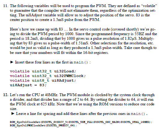
#include <xdc/runtime/Error.h>
#include <xdc/runtime/System.h>
/* BIOS Header files */
#include <ti/sysbios/BIOS.h>
#include <ti/sysbios/knl/Task.h>
/* TI-RTOS Header files */
#include <ti/drivers/GPIO.h>
#include <stdint.h>
#include <stdbool.h>
#include "inc/hw_memmap.h"
#include "inc/hw_types.h"
#include "driverlib/sysctl.h"
#include "driverlib/gpio.h"
#include "driverlib/debug.h"
#include "driverlib/pwm.h"
#include "driverlib/pin_map.h"
#include "inc/hw_gpio.h"
#include "driverlib/rom.h"
/* Example/Board Header files */
#include "Board.h"
// PWM variables
volatile uint32_t PWM_FREQUENCY;
volatile uint32_t ui32Load;
volatile uint32_t ui32PWMClock;
volatile uint8_t ui8Adjust;
/*
* ======== gpioButtonFxn0 ========
* Callback function for the GPIO interrupt on Board_BUTTON0.
*/
Void gpioButtonFxn0(Void)
{
/* Clear the GPIO interrupt*/
GPIO_clearInt(Board_BUTTON0);
ui8Adjust = 56; // PWM output to 1ms (0%)
PWMPulseWidthSet(PWM1_BASE, PWM_OUT_0, ui8Adjust * ui32Load / 1000);
GPIO_write(Board_LED0, Board_LED_OFF);
GPIO_write(Board_LED1, Board_LED_OFF);
GPIO_write(Board_LED2, Board_LED_ON);
}
/*
* ======== gpioButtonFxn1 ========
* Callback function for the GPIO interrupt on Board_BUTTON1.
* This may not be used for all boards.
*/
Void gpioButtonFxn1(Void)
{
/* Clear the GPIO interrupt*/
GPIO_clearInt(Board_BUTTON1);
ui8Adjust = 111; // PWM output to 2ms (100%)
PWMPulseWidthSet(PWM1_BASE, PWM_OUT_0, ui8Adjust * ui32Load / 1000);
GPIO_write(Board_LED0, Board_LED_OFF);
GPIO_write(Board_LED2, Board_LED_OFF);
GPIO_write(Board_LED1, Board_LED_ON);
}
Void pwmInit(Void)
{
// PWM settings
PWM_FREQUENCY = 55;
ui8Adjust = 83;
SysCtlClockSet(SYSCTL_SYSDIV_5|SYSCTL_USE_PLL|SYSCTL_OSC_MAIN|SYSCTL_XTAL_16MHZ);
SysCtlPWMClockSet(SYSCTL_PWMDIV_64);
SysCtlPeripheralEnable(SYSCTL_PERIPH_PWM1);
SysCtlPeripheralEnable(SYSCTL_PERIPH_GPIOD);
SysCtlPeripheralEnable(SYSCTL_PERIPH_GPIOF);
GPIOPinTypePWM(GPIO_PORTD_BASE, GPIO_PIN_0);
GPIOPinConfigure(GPIO_PD0_M1PWM0);
HWREG(GPIO_PORTF_BASE + GPIO_O_LOCK) = GPIO_LOCK_KEY;
HWREG(GPIO_PORTF_BASE + GPIO_O_CR) |= 0x01;
HWREG(GPIO_PORTF_BASE + GPIO_O_LOCK) = 0;
GPIODirModeSet(GPIO_PORTF_BASE, GPIO_PIN_4|GPIO_PIN_0, GPIO_DIR_MODE_IN);
GPIOPadConfigSet(GPIO_PORTF_BASE, GPIO_PIN_4|GPIO_PIN_0, GPIO_STRENGTH_2MA, GPIO_PIN_TYPE_STD_WPU);
ui32PWMClock = SysCtlClockGet() / 64;
ui32Load = (ui32PWMClock / PWM_FREQUENCY) - 1;
PWMGenConfigure(PWM1_BASE, PWM_GEN_0, PWM_GEN_MODE_DOWN);
PWMGenPeriodSet(PWM1_BASE, PWM_GEN_0, ui32Load);
PWMPulseWidthSet(PWM1_BASE, PWM_OUT_0, ui8Adjust * ui32Load / 1000);
PWMOutputState(PWM1_BASE, PWM_OUT_0_BIT, true);
PWMGenEnable(PWM1_BASE, PWM_GEN_0);
// Set PWM output = 50%
PWMPulseWidthSet(PWM1_BASE, PWM_OUT_0, ui8Adjust * ui32Load / 1000);
}
/*
* ======== main ========
*/
Int main(Void)
{
/* Call board init functions */
Board_initGeneral();
Board_initGPIO();
Board_initUART();
// PWM startup
pwmInit();
/* Turn on user LED */
GPIO_write(Board_LED0, Board_LED_ON);
System_printf("Starting the GPIO Interrupt example\nSystem provider is set"
" to SysMin. Halt the target and use ROV to view output.\n");
/* SysMin will only print to the console when you call flush or exit */
System_flush();
/* Initialize interrupts for all ports that need them */
GPIO_setupCallbacks(&Board_gpioCallbacks0);
/* Enable interrupts */
GPIO_enableInt(Board_BUTTON0, GPIO_INT_RISING);
GPIO_enableInt(Board_BUTTON1, GPIO_INT_RISING);
/*
* If more than one input pin is available for your device, interrupts
* will be enabled on Board_BUTTON1.
*/
//if (Board_BUTTON0 != Board_BUTTON1) {
/* Need to call setup if the button is on a different port */
//if (&Board_gpioCallbacks0 != &Board_gpioCallbacks1) {
// GPIO_setupCallbacks(&Board_gpioCallbacks1);
// }
// GPIO_enableInt(Board_BUTTON1, GPIO_INT_FALLING);
// }
/* Start BIOS */
BIOS_start();
return (0);
}
I have also attached a jpeg file with the wiring.

