HI guys!
Working on a project combining the TM4C123GH6PM, pwm outputs 0-3 + the CC3000 Boost wifi board.
The wifi setup should initialize after running a pwm_init() (setting all pwm parameters).
When not using (comment it out):
// PWM generator 0 and 1 enabled
PWMGenEnable(PWM1_BASE, PWM_GEN_0);
PWMGenEnable(PWM1_BASE, PWM_GEN_1);
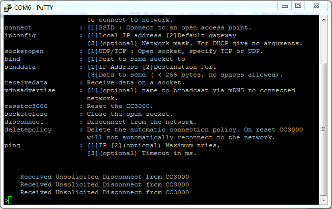
The wifi is working fine and I am able to send data to it from my computer.
So, the problem is the two lines above. Has anybody experienced anything similar? Does the PWMGenEnable restrict other functions? Has the pwm1_base anything to do with it? Could it be synchronizing problems?
For information, the EchoFxn() and pwmControl() run as Idle in the background.
Here is the code (important areas in bold and red):
/* XDCtools Header files */
#include <xdc/std.h>
#include <xdc/cfg/global.h>
#include <xdc/runtime/Error.h>
#include <xdc/runtime/Memory.h>
#include <xdc/runtime/System.h>
#include <string.h>
/* BIOS Header files */
#include <ti/sysbios/BIOS.h>
#include <ti/sysbios/knl/Task.h>
/* TI-RTOS Header files */
#include <ti/drivers/GPIO.h>
#include <ti/drivers/WiFi.h>
#include <stdint.h>
#include <stdbool.h>
#include "inc/hw_memmap.h"
#include "inc/hw_types.h"
#include "driverlib/sysctl.h"
#include "driverlib/gpio.h"
#include "driverlib/debug.h"
#include "driverlib/pwm.h"
#include "driverlib/pin_map.h"
#include "inc/hw_gpio.h"
#include "driverlib/rom.h"
/* SimpleLink Wi-Fi Host Driver Header files */
#include <cc3000_host_driver/include/common/cc3000_common.h>
#include <cc3000_host_driver/include/netapp.h>
#include <cc3000_host_driver/include/nvmem.h>
#include <cc3000_host_driver/include/socket.h>
#include <cc3000_host_driver/include/wlan.h>
/* Example/Board Header files */
#include "Board.h"
// TCP buffer size and port number
#define TCPPACKETSIZE 12
#define TCPPORT 1000
/* CC3000 firmware version compatible with this example */
#define PACKAGEID 1
#define PACKAGEBLDNUM 24
/* Flags set in callback */
Bool smartConfigFinished = FALSE;
Bool deviceConnected = FALSE;
Bool dhcpComplete = FALSE;
/* Buffer to hold data received */
Char buffer[TCPPACKETSIZE];
Char ipRecvd[4];
// PWM variables
volatile uint32_t PWM_FREQUENCY;
volatile uint32_t ui32Load;
volatile uint32_t ui32PWMClock;
volatile uint32_t pwm_motor_A;
volatile uint32_t pwm_motor_B;
volatile uint32_t pwm_motor_C;
volatile uint32_t pwm_motor_D;
/*
* ======== asynchCallback ========
* Callback for handling unsolicited events. A function pointer is passed in
* through the WiFi_Params to register the callback with the Host Driver.
*/
Void asynchCallback(long eventType, char *data, unsigned char length)
{
switch(eventType){
case HCI_EVNT_WLAN_ASYNC_SIMPLE_CONFIG_DONE:
/* Smart Config process has completed */
smartConfigFinished = TRUE;
break;
case HCI_EVNT_WLAN_UNSOL_CONNECT:
/* CC3000 connected to an AP */
deviceConnected = TRUE;
GPIO_write(Board_LED0, Board_LED_ON);
break;
case HCI_EVNT_WLAN_UNSOL_DISCONNECT:
/* CC3000 disconnected from an AP */
deviceConnected = FALSE;
GPIO_write(Board_LED0, Board_LED_OFF);
break;
case HCI_EVNT_WLAN_UNSOL_DHCP:
/* DHCP report */
dhcpComplete = TRUE;
ipRecvd[0] = data[3];
ipRecvd[1] = data[2];
ipRecvd[2] = data[1];
ipRecvd[3] = data[0];
break;
}
}
/*
* ======== smartConfigFxn ========
* Starts the Smart Config process which allows the user to tell the CC3000
* which AP to connect to, using a smart phone app. Downloads available here:
* http://www.ti.com/tool/smartconfig
*/
Void smartConfigFxn(Void)
{
UChar subnetMask[] = {0, 0, 0, 0};
UChar ipAddr[] = {0, 0, 0, 0};
UChar defaultGateway[] = {0, 0, 0, 0};
UChar dnsServer[] = {0, 0, 0, 0};
/* Acquire an IP address */
netapp_dhcp((unsigned long *)ipAddr, (unsigned long *)subnetMask,
(unsigned long *)defaultGateway, (unsigned long *)dnsServer);
/* Delete current policy */
wlan_ioctl_set_connection_policy(0, 0, 0);
/* Restart the CC3000 */
wlan_stop();
Task_sleep(50);
wlan_start(0);
/* Set Smart Config prefix and start Smart Config */
wlan_smart_config_set_prefix("TTT");
wlan_smart_config_start(0);
/* Wait for Smart Config to finish. LED will blink until complete. */
while (smartConfigFinished == 0) {
Task_sleep(400);
GPIO_toggle(Board_LED0);
}
/* Configure to connect automatically to the AP retrieved */
wlan_ioctl_set_connection_policy(0, 0, 1);
GPIO_write(Board_LED0, Board_LED_OFF);
/* Restart the CC3000 */
wlan_stop();
Task_sleep(50);
wlan_start(0);
/* Set connection flag to 'disconnected' */
deviceConnected = 0;
dhcpComplete = 0;
/* Mask out all non-required events */
wlan_set_event_mask(HCI_EVNT_WLAN_KEEPALIVE | HCI_EVNT_WLAN_UNSOL_INIT |
HCI_EVNT_WLAN_ASYNC_PING_REPORT);
}
/*
* ======== echoFxn ========
* Prints IP address and echos messages through TCP.
*
* Task for this function is created statically. See the project's .cfg file.
*/
Int nbytes;
Int status;
Int clientfd;
int n = 0;
Void echoFxn()
{
if(n == 0)
{
// Bool flag = TRUE;
Long lSocket;
sockaddr_in sLocalAddr;
sockaddr_in client_addr;
socklen_t addrlen = sizeof(client_addr);
UChar spNum[2] = {0};
ULong currButton;
ULong prevButton = 0;
WiFi_Params params;
WiFi_Handle handle;
/* Turn LED off. It will be used as a connection indicator */
GPIO_write(Board_LED0, Board_LED_OFF);
/* Open WiFi */
WiFi_Params_init(¶ms);
params.bitRate = 4000000;
handle = WiFi_open(Board_WIFI, Board_SPI_CC3000, asynchCallback, ¶ms);
/* Mask out all non-required events */
wlan_set_event_mask(HCI_EVNT_WLAN_KEEPALIVE | HCI_EVNT_WLAN_UNSOL_INIT |
HCI_EVNT_WLAN_ASYNC_PING_REPORT);
/* Check service pack version */
nvmem_read_sp_version(spNum);
if ((spNum[0] != PACKAGEID) || (spNum[1] != PACKAGEBLDNUM)) {
System_printf("You are using service pack version %d.%d! This example "
"is recommended for use\nwith %d.%d. Run the TI-RTOS "
"CC3000 Patcher example to get this version.\n\n",
spNum[0], spNum[1], PACKAGEID, PACKAGEBLDNUM);
System_flush();
}
/*
* Wait for the WiFi device to connect to an AP. If a profile for the AP in
* use has not been stored yet, press Board_BUTTON0 to put the CC3000 in
* Smart Config mode.
*/
while ((deviceConnected != TRUE) || (dhcpComplete != TRUE)) {
/*
* Start Smart Config if a button is pressed. This could be done with
* GPIO interrupts, but for simplicity polling is used to check the
* button.
*/
currButton = GPIO_read(Board_BUTTON0);
if((currButton == 0) && (prevButton != 0))
{
smartConfigFxn();
}
prevButton = currButton;
Task_sleep(50);
}
System_printf("CC3000 has connected to AP and acquired an IP address.\n");
/* Print IP address */
System_printf("IP Address: %d.%d.%d.%d\n", ipRecvd[0], ipRecvd[1],
ipRecvd[2], ipRecvd[3]);
System_flush();
/* Echo data using TCP */
lSocket = socket(AF_INET, SOCK_STREAM, IPPROTO_TCP);
if (lSocket == -1) {
System_printf("socket failed\n");
Task_exit();
}
memset((char *)&sLocalAddr, 0, sizeof(sLocalAddr));
sLocalAddr.sin_family = AF_INET;
sLocalAddr.sin_addr.s_addr = htonl(0);
sLocalAddr.sin_port = htons(TCPPORT);
status = bind(lSocket, (const sockaddr*)&sLocalAddr, sizeof(sLocalAddr));
if (status < 0) {
System_printf("bind failed\n");
closesocket(lSocket);
Task_exit();
}
if (listen(lSocket, 0) == -1){
System_printf("listen failed\n");
closesocket(lSocket);
Task_exit();
}
do {
/* Wait for incoming request */
clientfd = accept(lSocket, (sockaddr*)&client_addr, &addrlen);
Task_sleep(300);
} while (clientfd == SOC_IN_PROGRESS);
if (clientfd == -1) {
System_printf("accept failed\n");
closesocket(lSocket);
Task_exit();
}
if(nbytes == -1)
{
System_printf("Closing clientfd 0x%x.\n", clientfd);
closesocket(clientfd);
closesocket(lSocket);
WiFi_close(handle);
}
}
n = 1;
nbytes = recv(clientfd, buffer, TCPPACKETSIZE, 0); // read tcp buffer
pwm_motor_A = (buffer[0]-48)*100 + (buffer[1]-48)*10 + (buffer[2]-48)*1; // decode buffer index 0-3 = motor_A
pwm_motor_B = (buffer[3]-48)*100 + (buffer[4]-48)*10 + (buffer[5]-48)*1; // decode buffer index 4-7 = motor_B
pwm_motor_C = (buffer[6]-48)*100 + (buffer[7]-48)*10 + (buffer[8]-48)*1; // decode buffer index 8-11 = motor_C
pwm_motor_D = (buffer[9]-48)*100 + (buffer[10]-48)*10 + (buffer[11]-48)*1; // decode buffer index 12-15 = motor_D
}
Void pwmInit()
{
// PWM settings
PWM_FREQUENCY = 400;
pwm_motor_A = 440;
pwm_motor_B = 440;
pwm_motor_C = 440;
pwm_motor_D = 440;
SysCtlClockSet(SYSCTL_SYSDIV_5|SYSCTL_USE_PLL|SYSCTL_OSC_MAIN|SYSCTL_XTAL_16MHZ);
SysCtlPWMClockSet(SYSCTL_PWMDIV_64);
SysCtlPeripheralEnable(SYSCTL_PERIPH_PWM1);
SysCtlPeripheralEnable(SYSCTL_PERIPH_GPIOE); // connector J1, pin PE4 and PE5
SysCtlPeripheralEnable(SYSCTL_PERIPH_GPIOF); // connector J3, pin PD0 and PD1
// PWM PD0, motor A
GPIOPinTypePWM(GPIO_PORTD_BASE, GPIO_PIN_0);
GPIOPinConfigure(GPIO_PD0_M1PWM0);
// PWM PD1, motor B
GPIOPinTypePWM(GPIO_PORTD_BASE, GPIO_PIN_1);
GPIOPinConfigure(GPIO_PD1_M1PWM1);
// PWM PE4, motor C
GPIOPinTypePWM(GPIO_PORTE_BASE, GPIO_PIN_4);
GPIOPinConfigure(GPIO_PE4_M1PWM2);
// PWM PE5, motor D
GPIOPinTypePWM(GPIO_PORTE_BASE, GPIO_PIN_5);
GPIOPinConfigure(GPIO_PE5_M1PWM3);
// PWM clk and frequency
ui32PWMClock = SysCtlClockGet() / 64;
ui32Load = (ui32PWMClock / PWM_FREQUENCY) - 1;
PWMGenConfigure(PWM1_BASE, PWM_GEN_0, PWM_GEN_MODE_DOWN);
PWMGenPeriodSet(PWM1_BASE, PWM_GEN_0, ui32Load);
PWMGenConfigure(PWM1_BASE, PWM_GEN_1, PWM_GEN_MODE_DOWN);
PWMGenPeriodSet(PWM1_BASE, PWM_GEN_1, ui32Load);
// PWM 0 and 1
PWMPulseWidthSet(PWM1_BASE, PWM_OUT_0, (pwm_motor_A * ui32Load) / 1000);
PWMPulseWidthSet(PWM1_BASE, PWM_OUT_1, (pwm_motor_B * ui32Load) / 1000);
PWMOutputState(PWM1_BASE, PWM_OUT_0_BIT, true);
PWMOutputState(PWM1_BASE, PWM_OUT_1_BIT, true);
// PWM 2 and 3
PWMPulseWidthSet(PWM1_BASE, PWM_OUT_2, (pwm_motor_C * ui32Load) / 1000);
PWMPulseWidthSet(PWM1_BASE, PWM_OUT_3, (pwm_motor_D * ui32Load) / 1000);
PWMOutputState(PWM1_BASE, PWM_OUT_2_BIT, true);
PWMOutputState(PWM1_BASE, PWM_OUT_3_BIT, true);
// PWM generator 0 and 1 enabled
PWMGenEnable(PWM1_BASE, PWM_GEN_0);
PWMGenEnable(PWM1_BASE, PWM_GEN_1);
}
Void pwmControl()
{
PWMPulseWidthSet(PWM1_BASE, PWM_OUT_0, (pwm_motor_A * ui32Load) / 1000);
PWMPulseWidthSet(PWM1_BASE, PWM_OUT_1, (pwm_motor_B * ui32Load) / 1000);
PWMPulseWidthSet(PWM1_BASE, PWM_OUT_2, (pwm_motor_C * ui32Load) / 1000);
PWMPulseWidthSet(PWM1_BASE, PWM_OUT_3, (pwm_motor_D * ui32Load) / 1000);
}
/*
* ======== main ========
*/
Int main(Void)
{
/* Call board init functions. */
Board_initGeneral();
Board_initGPIO();
Board_initWiFi();
pwmInit();
/* Turn on user LED */
GPIO_write(Board_LED0, Board_LED_ON);
System_printf("Starting the Quad Control CC3000 system\n");
/* SysMin will only print to the console when you call flush or exit */
System_flush();
/* Start BIOS */
BIOS_start();
return (0);
}