Because of the holidays, TI E2E™ design support forum responses will be delayed from Dec. 25 through Jan. 2. Thank you for your patience.

This thread has been locked.

If you have a related question, please click the "Ask a related question" button in the top right corner. The newly created question will be automatically linked to this question.

I have a question about controlling multiple SPI(SSI) slave devices

Hello, I have a question about controlling multiple SPI(SSI) slave devices.(Please understand my poor English...)

I'm using TM4C123BH6PMI MCU, a 3-axis digital accelerometer(ST H3LIS331DL), and a 3-axis digital output gyroscope sensor(ST L3G4200D).

I'm trying to control these two sensors using SPI interface at SSI1 port.

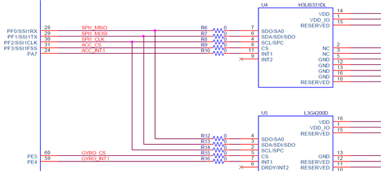
1.

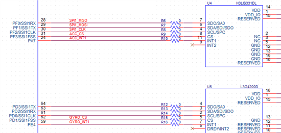
2.

Which picture is the correct connection?

Are both ways are possible to control both sensors? Or is it not a proper way?

(PE4, PE5 is a GPIO)

  • Hi,

    From hardware point of view, both versions are correct. What should concern most is the software point of view: do both chips have the same protocol (in terms of SPI operating mode, bits, bytes) - since you provide interrupt from each chip, if two interrupts comes at same time, how you will manage them - after finding out which interrupt to process, you must re-configure the SPI according to that chip and only after that you will be able to process that interrupt. At this point an analysis of all your interrupts must be done - you may have also other interrupts and all must be prioritized. Try to think in advance at these problems.

    (The worst case scenario: a lower priority interrupt just done reconfiguration of SPI and a higher interrupt priority just butt in, reconfigure again the SPI , run the rest of interrupt handler and quitt - how the lower interrupt will react in this case?)

    Petrei

  • Hello, thanks replying Petrei ^^

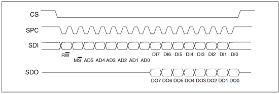
    1. Both sensors have the same SPI protocol as the picture below.

    <SPI protocol of sensors>

    2. Each sensors provide an inertial interrupt to the MCU, but I've never thought about managing mutiple interrupts and the priorities of the interrupts. Thanks for the tip!!!

    - Additional Questions -

    Actually I've already requested a PCB Artwork to a certain company with a schematic which followed the first connection of SPI.

    I'm suspicious that whther SSI1CLK will activate as a SPI clock when using  PE5 pin as a Chip Select(CS, Low-Edge Triggered). Also the other SSI1Rx, SSI1Tx too.

    Do I have to add some codes to activate SSI1CLK manually?

  • Hi,

    SSICLK is generated automatically when you write to SSI data register, so you cannot activate it manually (unless you use softspi which I do not suggest to think to).

    In other words, is it there a particular reason for not using separate SPI interfaces (you have four at your disposition) - looks like you are cutting of one of your legs since you have too many - still you may have some problems with the software - not speaking about the interrupt problems, which are real ones.

    Petrei

    EDIT: you should configure SSIFss as GPIO pin to act as chip select and manage it separately for each device, so complications...