This thread has been locked.

If you have a related question, please click the "Ask a related question" button in the top right corner. The newly created question will be automatically linked to this question.

ADC channels bleeding into each other.

Other Parts Discussed in Thread: MSP430G2553

 I'm working with a Tiva TM4C123GE6 part and I'm using a single ADC ( adc0) in 1Msps mode.  I'm running across 8 channels and over sampling by 2.  So, 500k and the adc is triggered by a timer at 50k cycles.  This seems to work ok until I add signals onto more than 1 of the 8 channels and I get some very off the wall data points.  I have the 8 channels tied into a launch pad that oscillates two pins at different frequencies.  So, 4 channels goes to one launchpad pin and 4 channels goes to the other pin.  When I pull the data points down I've saved for each channel and plot it..it looks like some of the channels might be bleeding over.  The signals are rectangular waves and when it is supposed to be zero i'll get a random max value and when it is supposed to be high I'll get a random low value.  The only channel that works reliably for some reason is the very last one.  The launchpad isn't driving any loads or anything.  Is this situation an example of me running the adc too fast?  I wouldn't have thought this, but do I need to back the sample rate for the ADC down from 1Msps to 500ksps to solve this problem or is it more likely that something else is going on? 

If i run this setup using a single channel configuration it works perfectly. 

Thanks,

Rob

  • Hi,

    You said:

    So, 4 channels goes to one launchpad pin and 4 channels goes to the other pin

    Can you explain more this? Eventualy an electrical diagram? Did you used an external multiplexer for that?

    Petrei

  • Hey Petrei, believe it or not its that simple.  I've got pin 1.0 on a launch pad toggling at say 660 hz.  that pin is connected to PE3, PE2, PE1, PE0 (A0, A1, A2, A3) on theTM4C.  Pin 1.6 on the launchpad is toggling ~333Hz and it is directly connected (with wire) to pins PD3, PD2, PD1, PD0 (A4, A5, A6, A7) on the TM4C.  There is no multiplexor, no buffers they are just wired together.

    And as a side note....I pulled the jumpers on the lanchpad so those pins don't drive the two LEDs that are on there.  There are no loads attached to the pins on the launchpad that I'm looking at with the TM4C.

  • Hi, 

    As you said, then the first eight are OK. What about more than eight? How did you added the nineth one? Did you used the second sequencer? 

    Petrei

  • Im using 8 channels only....no ninth channel. A0 to a7. Ive configured the sequencer to end on channel 7. If you look at the picture of my data plots it shows a little more clearly whats going on. The first 8 are not ok. The only data that is correct is the 8th channel. Channels a0 to a6 all have errors. Channel a7 looks correct. Ill post up my configuration code when I get home. Im using adc0 only and using the 8 step sequencer. Im using sequencer ss0. Does it seem llike a setup like this should yield clean accurate data? Said differently, should the launchpad be able to drive the adc ok in this test setup? Could there be a problem switching through the channels at 1Msps because its too fast causing residual charge from one channel to be carried over to other channels? The problem doesnt seem to appear when a use one single channel but does appear when I sample more than 1 channel.
  • Hi,

    Try first to disable oversampling - the sampling may be too fast - the phenomenon may be similar to time skew - for sure you have a difference in time constants from low to high and high to low transitions - the equivalent input circuit in user manual suggest that. 

    Also you may read also this application note: http://www.ti.com/lit/an/slyt179/slyt179.pdf

    Petrei

  • Robbie,

    I don't fully understand your connections, but are any inputs that you are using left floating (that is, not connected to a source)?

    As others have stated, a connection diagram would be useful.

    Regards, Vito

  • Hey sorry for not being more clear about my connections.  I just got home and drew up a sketch.  Attached is the pdf of my connections.  There are no circuits or IC's/parts in between the MSP430G2553 and the TM4C.  I just connected 1 pin on the 2553 to 4 channels on the TM4C and another pin on the 2553 to 4 channels of the TM4C.  I only cycle through 8 channels (A0-A7).

    3073.Block diagram.pdf

    Here is the config function for the ADC in this mode.

            SysCtlPeripheralEnable(SYSCTL_PERIPH_ADC0);        // Enable ADC0 peripheral
    ADCSequenceConfigure(ADC0_BASE, 0, ADC_TRIGGER_PROCESSOR, 0); ADCHardwareOversampleConfigure(ADC0_BASE, OverSample); ADCSequenceStepConfigure(ADC0_BASE, 0, 0, ADC_CTL_CH0); ADCSequenceStepConfigure(ADC0_BASE, 0, 1, ADC_CTL_CH1); ADCSequenceStepConfigure(ADC0_BASE, 0, 2, ADC_CTL_CH2); ADCSequenceStepConfigure(ADC0_BASE, 0, 3, ADC_CTL_CH3); ADCSequenceStepConfigure(ADC0_BASE, 0, 4, ADC_CTL_CH4); ADCSequenceStepConfigure(ADC0_BASE, 0, 5, ADC_CTL_CH5); ADCSequenceStepConfigure(ADC0_BASE, 0, 6, ADC_CTL_CH6); ADCSequenceStepConfigure(ADC0_BASE, 0, 7, ADC_CTL_CH7 | ADC_CTL_IE | ADC_CTL_END); ADCIntRegister(ADC0_BASE, 0, ADC0IntHandler8ch); ADCIntClear(ADC0_BASE, 0); ADCIntEnable(ADC0_BASE, 0); ADCSequenceEnable(ADC0_BASE, 0);

  • Hello Robbie,

    Couple of items to check

    1. Are the GPIO configured for ADC Function? I do not see that in the code, so at this point my assumption would be that you may be using the pin mux utility?

    2. Before enabling the clock to the ADC, can you Soft Reset the ADC Peripheral?

    Regards

    Amit

  • The initial phrase of "ADC channel bleeding" might come quite close to the point. Such effects are most often caused by inappropriate source impedance. The configured sample time and sample rate are probably not sufficient to fully charge/discharge the sampling cap to the value of the following channel, resulting in the observed "bleeding" effect. That would boil down to calculating a simple RC element, where C is fixed. As a solution, either reduce R (provide more current at the inputs, i.e. use  buffer amplifiers), or increase the sampling time (reducing sampling frequency).

    A simple test is to increase the sampling time by factor 2 or 4. If the bleeding effect is reduces or disappears, it's purely electrical.

  • Thanks for the posts.  I've been working on implementing these ideas tonight.  For some reason when I use the code below:

            //
            // Configure ADC0
            //
           SysCtlADCSpeedSet(SYSCTL_ADCSPEED_500KSPS);
            SysCtlPeripheralEnable(SYSCTL_PERIPH_GPIOD);
            SysCtlPeripheralEnable(SYSCTL_PERIPH_GPIOE);	// Enable PORTE so we can use A0-A3
    	SysCtlPeripheralEnable(SYSCTL_PERIPH_ADC0);		// Enable ADC0 peripheral
    	//
    	// Set GPIO PE3 as an ADC input
    	GPIOPinTypeADC(GPIO_PORTE_BASE, GPIO_PIN_0 | GPIO_PIN_1 | GPIO_PIN_2 | GPIO_PIN_3);
    	GPIOPinTypeADC(GPIO_PORTD_BASE, GPIO_PIN_0 | GPIO_PIN_1 | GPIO_PIN_2 | GPIO_PIN_3);
    	ADCSequenceConfigure(ADC0_BASE, 0, ADC_TRIGGER_PROCESSOR, 0);
    
    	ADCHardwareOversampleConfigure(ADC0_BASE, OverSample);
    
    	ADCSequenceStepConfigure(ADC0_BASE, 0, 0, ADC_CTL_CH0);
    	ADCSequenceStepConfigure(ADC0_BASE, 0, 1, ADC_CTL_CH1);
    	ADCSequenceStepConfigure(ADC0_BASE, 0, 2, ADC_CTL_CH2);
    	ADCSequenceStepConfigure(ADC0_BASE, 0, 3, ADC_CTL_CH3);
    	ADCSequenceStepConfigure(ADC0_BASE, 0, 4, ADC_CTL_CH4);
    	ADCSequenceStepConfigure(ADC0_BASE, 0, 5, ADC_CTL_CH5);
    	ADCSequenceStepConfigure(ADC0_BASE, 0, 6, ADC_CTL_CH6);
    	ADCSequenceStepConfigure(ADC0_BASE, 0, 7, ADC_CTL_CH7 | ADC_CTL_IE | ADC_CTL_END);
    
    	ADCIntRegister(ADC0_BASE, 0, ADC0IntHandler8ch);
    
    	ADCIntClear(ADC0_BASE, 0);
    
    	ADCIntEnable(ADC0_BASE, 0);
    
    	ADCSequenceEnable(ADC0_BASE, 0);

    I notice that register SYSCTL_DC1_ADC0SPD is still set at 1Msps.  I've tried placing the

    SysCtlADCSpeedSet(SYSCTL_ADCSPEED_500KSPS);

    everywhere I can think of and it doesn't change.  From reading the part's data sheet it seems like this register should change to 0x2 for 500ksps.  Am I missing something here?  Even if i put the call to changed to 500ksps after the ADC is configured or right after it is enabled it doesn't make a difference when I check this register with the debugger.

    Another note is that the adc, when recording 8 channels, is triggered by a timer.  When the timer triggers the adc to sample at 10ksps all the data is fine.  When the timer triggers it to run at 50ksps it isn't.  If you look at the data it looks like the adc is saving data from one channel on another channel.  For example when channel 2 is low (0 volts) and channel 1 is high (3.3 volts) it puts a sample from channel 2 on channel one.  Basically what I'm saying is that it isn't creep or a little variation.  When channel one is in the middle of sampling the peak of the square wave there is a random 0V sample in the middle of say 500 3.3V samples.  Said differently, when channel one is supposed have 500 samples of ~255 it instead has 499 of 255 and 1 of 0. 


    When I leave the adc configured to 1Msps and just slow down the timer that triggers the adc this problem goes away.  I still want to slow the ADC down to 500k as stated above, but this is just some more information.


    Testing Update:

    -----------------

    So I've verified now that I've dropped the sampling speed down to 500ksps with the below instructions.

    	uint32_t adcget;
    	adcget = SysCtlADCSpeedGet();

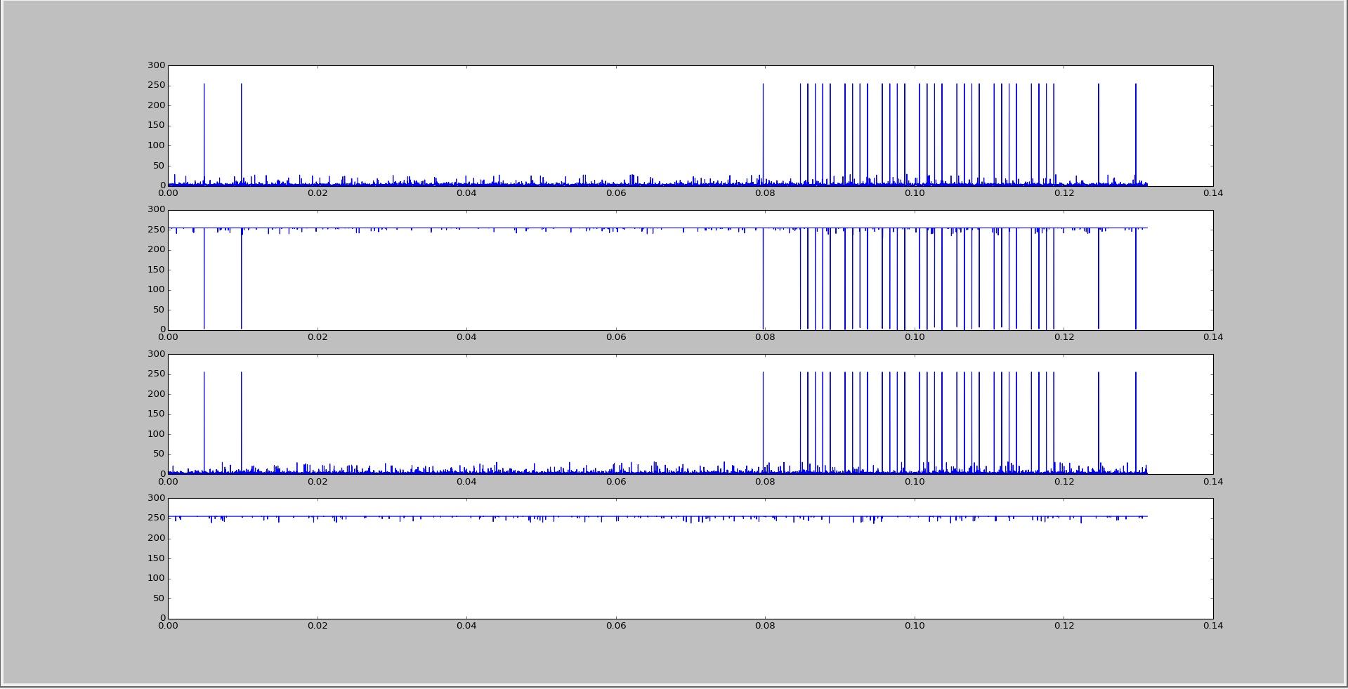
    I'm not sure whats up with those registers, but this function returns the A00 which correlates to the constant for 500ksps.  the issue here is that I need 500ksps performance.  I've also hooked 4 of the Tiva ADC channels up to ground and 4 of the Tiva adc channels up to VCC and I see the exact same problem as when I record the rectangular wave.  Below is a screen shot of the data from the 4 channels.  The top plot is connected directly to ground.  The second is connected to Vcc (3.3V) the third is connected to ground and the 4'th is connected to Vcc.  This is running at 500ksps. 

  • Hello Robbie,

    What is the system frequency you are running the TM4C part at?

    The SysCtlADCSpeedSet does not modify the SYSCTL.DC1 register but the SYSCTL.RCGC0 register.

    BTW thanks for the input on the Timer Period to trigger the ADC, as it is a vital clue. The ADC is configured to run at 500ksps for 8 channels. The timer at 50ksps does not work. So for 8 channels it computes to 400ksps leaving 100ksps worth of time for the Cortex to read the data. It suggests that the system clock is not as fast to read out the data from the ADC FIFO. Hence the first question.

    Could you change the System Clock to run at 80MHz or increase the ADC Sampling Rate to 1MSPS as an experiment to give validity to the hypothesis.

    Regards

    Amit

  • Hey Amit!  Actually my system clock is setup for 80Mhz.  I'm using this instruction below:

        //
        // Set the clocking to run from the PLL at 80MHz.
        //
        SysCtlClockSet(SYSCTL_SYSDIV_2_5 | SYSCTL_USE_PLL | SYSCTL_XTAL_16MHZ | SYSCTL_OSC_MAIN);//SYSCTL_OSC_INT);		// external crystal, 80Mhz via PLL

    I do have some processing going on in my ADCISR routine.  It is shown below for 8 channels.

    	ADCIntClear(ADC0_BASE, 0);
    
    
    	ADCSequenceDataGet(ADC0_BASE, 0, &ADC_data_8byte[0]);
    
    	switch(AdcISRState){
    
    	case 0:
    		if(data_storage_count < 512){
    
    
    			ADCsampleBuffer1[data_storage_count] = ADC_data_8byte[0] >> 4;
    			data_storage_count++;
    
    			ADCsampleBuffer1[data_storage_count] = ADC_data_8byte[1] >> 4;
    			data_storage_count++;
    
    			ADCsampleBuffer1[data_storage_count] = ADC_data_8byte[2] >> 4;
    			data_storage_count++;
    
    			ADCsampleBuffer1[data_storage_count] = ADC_data_8byte[3] >> 4;
    			data_storage_count++;
    
    			ADCsampleBuffer1[data_storage_count] = ADC_data_8byte[4] >> 4;
    			data_storage_count++;
    
    			ADCsampleBuffer1[data_storage_count] = ADC_data_8byte[5] >> 4;
    			data_storage_count++;
    
    			ADCsampleBuffer1[data_storage_count] = ADC_data_8byte[6] >> 4;
    			data_storage_count++;
    
    			ADCsampleBuffer1[data_storage_count] = ADC_data_8byte[7] >> 4;
    			data_storage_count++;
    
    
    			if(data_storage_count > 511){
    				//multiChannel_cnt = 0;
    				data_storage_count2 = 0;
    				AdcISRState = 1;
    				ADCsampleBuffer1_full = 1;
    				ADC_data_flag = 1;
    			}
    		}
    		break;


    There is a second state in this switch statement that is the same as the first...this ISR just bounces between these two states circular buffering data blocks. 

    At 80 Mhz in this configuration I would have 1280 clock cycles to get through this ISR.  1/500,000 = 16uS and so you then do (16uS) / [1/80,000,000] = 1280. Does it seem reasonable that I'd make it through this?  I'm also running the USB stack which may add some unseen complexity. 


    Running 8 channels at 400k at 80Mhz using 1Msps still yields some off the wall data samples as shown in some of these plots.


    Thanks again for you help,

    Rob

  • Hello Robbie,

    At 50ksps Timer you have 20us between two full conversions. For converting the 8 channels you have 16 of time taken, which would leave 4 us worth of time for the Interrupt and any background tasks which is 320 System Clock cycles. At 1MSPS the same works out to 960 clock cycles.

    To make sure of the load presented by the ISR, if you can toggle a GPIO high when entering the ISR and low when exiting it, it would give a good estimate on the time it is taking in the ISR

    To make sure of background load, you can toggle a GPIO Low->High->Low when the conversion is started (This is possible if you are using a timer to trigger an interrupt to the CPU to start ADC Conversion). The time from this GPIO toggle + 16us is where you should see the ISR-GPIO toggling.

    Regards

    Amit

  • You said that 16us are already taken up because of the 8 channels. Is this because each channel takes two 1Msps cycles to convert the sample yielding 16 us of overhead for conversion before I get to the isr?
  • Hello Robbie,

    Yes. That is correct. That 16us out of 20us for conversion.

    Alternatively, you can set the IE bit for 4th conversion as well. As a result you can read out while the next 4 channels are converting effectively creating a pipeline. This may complicate the ISR.

    Regards

    Amit

  • Ill spend some time thinking about that tactic but I imagine there would be a little more overhead with that approach but not sure so I may fiddle with it a bit. First I'm going to try disabling GIE bitwhen I enter the isr and enable when I'm done in the isr to see if the usb stack or something else is interfering. I imagine this will be unsuccessful. The part that is bothering me is that the last channel. Channel a7 which is last in the sequence of the 8 channels never has a single anomaly no matter what signal I sample. It always works. I would think failure to meet timing would mean that the anomalies show up intermittently on all channels.
  • Alright, so first I want to thank you guys for the help.  As usual, this is an outstanding resource.  I've finally figured out what was going on.

    I just briefly mentioned that I was using the USB stack and that it was running.  Turns out that it was servicing stuff (not educated enough yet to explain exactly what it was doing), but it would interrupt and every so often the Tiva part wouldn't come out of the USB interrupt fast enough to make it through the ISR for the adc.  I changed to priority of the USB stack after enumeration down a level and now the ADC and ONLY the ADC has the highest interrupt priority.  This fixed my problem.  All my channels 1,2,4,8 are working ok now at all speeds. 


    I just used the

    IntPrioritySet(60, 0x20);

    instruction to change the interrupt.  The 60 is the INT_USB0, but instead of including the .h file for the particular tiva part i'm using in my USB stack I just found the definition and plugged the number in.  This information is in the part number.h file if anyone is interested.  Long story short, put some thought into interrupt priorities because when your timing is super tight like this they apparently matter ;)


    Thanks again for all the help guys!

    Rob