Because of the holidays, TI E2E™ design support forum responses will be delayed from Dec. 25 through Jan. 2. Thank you for your patience.

This thread has been locked.

If you have a related question, please click the "Ask a related question" button in the top right corner. The newly created question will be automatically linked to this question.

I2C burst sent on Tiva tm4c129dncpdt.

Other Parts Discussed in Thread: TM4C129DNCPDT

I  have  Tiva tm4c129dncpdt.  I try to put data { 0x06, 0xff} to I2C address 0x22. But the last data 0xff can't be sent .

Below is my code:

void I2cWriteTest(void)
{

SysCtlPeripheralEnable( SYSCTL_PERIPH_I2C1 );
I2CMasterEnable(I2C1_BASE);
SysCtlPeripheralReset(SYSCTL_PERIPH_I2C1);

SysCtlPeripheralEnable( SYSCTL_PERIPH_GPIOG);
GPIOPinConfigure( GPIO_PG0_I2C1SCL );
GPIOPinTypeI2CSCL(GPIO_PORTG_BASE, GPIO_PIN_0);
GPIOPinConfigure( GPIO_PG1_I2C1SDA );
GPIOPinTypeI2C( GPIO_PORTG_BASE , GPIO_PIN_1) ;


I2CMasterInitExpClk(I2C1_BASE, ui32SysClock, true);

I2CSlaveInit(I2C1_BASE, 0x22 );

I2CMasterSlaveAddrSet(I2C1_BASE, 0x22, false);

//Send the first byte.
I2CMasterDataPut( I2C1_BASE, 0x06 );
I2CMasterControl( I2C1_BASE, I2C_MASTER_CMD_BURST_SEND_START );


while(ROM_I2CMasterBusy(I2C1_BASE)) {}

I2CMasterDataPut( I2C1_BASE, 0xff );
I2CMasterControl( I2C1_BASE, I2C_MASTER_CMD_BURST_SEND_FINISH );
while(ROM_I2CMasterBusy(I2C1_BASE)) {}

}

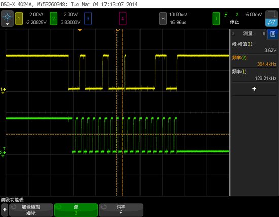
The last data 0xff can't be sent .  The signal as below:

  • Hi Elaine

    Looking at the code I believe you are sending the data to I2C1 Slave. Is that correct? If yes, then you need to read the data from the Slave's Data Register first before sending the next Data Byte from the master. The reason why I am saying so is because as per the scope plot the SCL remains low.

    Regards

    Amit Ashara

  • Hi Amit,

    Yes, I am sending the data to I2C1 Slave.

    I added code as below, bout got the same result. 

    SysCtlPeripheralEnable( SYSCTL_PERIPH_I2C1 );
    I2CMasterEnable(I2C1_BASE);
    SysCtlPeripheralReset(SYSCTL_PERIPH_I2C1);

    SysCtlPeripheralEnable( SYSCTL_PERIPH_GPIOG);
    GPIOPinConfigure( GPIO_PG0_I2C1SCL );
    GPIOPinTypeI2CSCL(GPIO_PORTG_BASE, GPIO_PIN_0);
    GPIOPinConfigure( GPIO_PG1_I2C1SDA );
    GPIOPinTypeI2C( GPIO_PORTG_BASE , GPIO_PIN_1) ;


    I2CMasterInitExpClk(I2C1_BASE, ui32SysClock, true);

    I2CSlaveInit(I2C1_BASE, 0x22 );

    I2CMasterSlaveAddrSet(I2C1_BASE, 0x22, false);

    //Send the first byte.
    I2CMasterDataPut( I2C1_BASE, 0x06 );
    I2CMasterControl( I2C1_BASE, I2C_MASTER_CMD_BURST_SEND_START );

    while(ROM_I2CMasterBusy(I2C1_BASE)) {}


    I2CMasterSlaveAddrSet(I2C1_BASE, 0x22, true);
    back1=I2CMasterDataGet(I2C1_BASE);

    I2CMasterControl( I2C1_BASE, I2C_MASTER_CMD_SINGLE_RECEIVE );
    while(ROM_I2CMasterBusy(I2C1_BASE)) {}

    I2CMasterSlaveAddrSet(I2C1_BASE, 0x22, false);

    I2CMasterDataPut( I2C1_BASE, 0xff );
    I2CMasterControl( I2C1_BASE, I2C_MASTER_CMD_BURST_SEND_FINISH );
    while(ROM_I2CMasterBusy(I2C1_BASE)) {}

    What I want to do is as below

  • Hi Elaine,

    If this a loopback then you would need to enable the loopback mode

    HWREG(I2C1_BASE + I2C_O_MCR) |= 0x01;

    Secondly the code would look more like the below for the image you have given.

    //Send the first byte.
    I2CMasterDataPut( I2C1_BASE, 0x06 );
    I2CMasterControl( I2C1_BASE, I2C_MASTER_CMD_BURST_SEND_START );

    while(ROM_I2CMasterBusy(I2C1_BASE)) {}

    while(!(I2CSlaveStatus(I2C1_BASE) & I2C_SLAVE_ACT_RREQ)) {}

    back1=I2CSlaveDataGet(I2C1_BASE);

    I2CMasterDataPut( I2C1_BASE, 0xff );

    I2CMasterControl( I2C1_BASE, I2C_MASTER_CMD_BURST_SEND_FINISH );
    while(ROM_I2CMasterBusy(I2C1_BASE)) {}

    while(!(I2CSlaveStatus(I2C1_BASE) & I2C_SLAVE_ACT_RREQ)) {}

    back2=I2CSlaveDataGet(I2C1_BASE);

    Regards

    Amit

  • Hi Amit,

    Thank you very much.  The waveform looks correct now.

    It's not a loopback mode.  It is connected to MAX7313.

    I got back1 and back2 as loopback data. 

  • Hi Amit,

    It still have problems.

    Now I want to sent three bytes data( 0x05, 0x12, 0x23). It's not a loopback mode.  The data were sent to slave address 0x40.

    I modify the code as below:

    SysCtlPeripheralEnable( I2cMap[index].PeriphI2c );
    I2CMasterEnable(ui2cBase);//I2C1_BASE
    SysCtlPeripheralReset(I2cMap[index].PeriphI2c);

    // Configure the I2C SCL and SDA pins for I2C operation.
    SysCtlPeripheralEnable( I2cMap[index].PeriphGpio);
    GPIOPinConfigure( I2cMap[index].SCL );
    GPIOPinTypeI2CSCL(I2cMap[index].IoBase, I2cMap[index].IoScl);
    GPIOPinConfigure( I2cMap[index].SDA );
    GPIOPinTypeI2C( I2cMap[index].IoBase , I2cMap[index].IoSda) ;


    if(uiSpeed==400000)
    I2CMasterInitExpClk(ui2cBase, ui32SysClock, true);
    else
    I2CMasterInitExpClk(ui2cBase, ui32SysClock, false);

    //I2CSlaveEnable(ui2cBase);
    I2CSlaveInit(ui2cBase, address );

    I2CMasterSlaveAddrSet(ui2cBase, address, false);

    if(length==1)
    {
    I2CMasterDataPut( ui2cBase, *pData );
    I2CMasterControl( ui2cBase, I2C_MASTER_CMD_SINGLE_SEND );


    while(ROM_I2CMasterBusy(ui2cBase)) {}
    }
    else
    {
    //Send the first byte.
    I2CMasterDataPut( ui2cBase, pData[0] );
    I2CMasterControl( ui2cBase, I2C_MASTER_CMD_BURST_SEND_START );
    while(ROM_I2CMasterBusy(ui2cBase)) {}

    while(!(I2CSlaveStatus(ui2cBase) & I2C_SLAVE_ACT_RREQ)) {}
    back1=I2CSlaveDataGet(ui2cBase);

    length -- ;
    i=1;
    while( length)
    {
    length--;
    // UartOsPrintf("length = %x\n", length );

    I2CMasterDataPut( ui2cBase, pData[i] );

    if(length)
    I2CMasterControl( ui2cBase, I2C_MASTER_CMD_BURST_SEND_CONT );
    else
    I2CMasterControl( ui2cBase, I2C_MASTER_CMD_BURST_SEND_FINISH );

    while(I2CMasterBusy(ui2cBase)) {}

    while(!(I2CSlaveStatus(ui2cBase) & I2C_SLAVE_ACT_RREQ)) {}
    back2=I2CSlaveDataGet(ui2cBase);

    i++;
    }


    }

    UartOsPrintf("Read = %x, %x\n", back1, back2 );
    uint32_t i2cError = ROM_I2CMasterErr( ui2cBase );
    UartOsPrintf("Error = %x\n", i2cError );

    The waveform as below:

    It only sent address and first two bytes data.

    The code run into the last while : while(!(I2CSlaveStatus(ui2cBase) & I2C_SLAVE_ACT_RREQ)) {}

    If I mark the last while loop

    //while(!(I2CSlaveStatus(ui2cBase) & I2C_SLAVE_ACT_RREQ)) {}
    //back2=I2CSlaveDataGet(ui2cBase);

    The waveform as below:

    Waveform only show address, first bye, third byte data and don't stop.

  • Hello Elaine,

    Please change the following loop

    while(I2CMasterBusy(ui2cBase)) {}

    to

    while(!I2CMasterBusy(ui2cBase)) {}

    while(I2CMasterBusy(ui2cBase)) {}

    Secondly what is the value of length you are programming for the 3 bytes?

    Regards

    Amit

  • Hi Amit,

    I got this waveform


    The value of length is 3.

    The waveform don't have stop condition and run in last while:while(I2CMasterBusy(ui2cBase)) {}

    Regards,

    Elaine

  • Hello Elaine,

    So now the 3 bytes are getting transmitted correctly but no STOP condition on the bus? This is after the last code change you made?

    Can you put a break-point at the FINISH control condition in code and see if it is reaching the condition and at the same time on the scope only 2 bytes are getting transmitted.

    Secondly is this code still using Master-Slave Loopback?

    Regards

    Amit

  • Hi Amit,

    Yes, that's the result after change the loop.

    When I put a break-point at the Finish control condition, the scope only got 2 bytes.  Is it correct?

    It is not in Master-Slave loopback mode.  I want to run in master mode and sent data to slave device.

    Regards,

    Elaine

  • Hello Elaine,

    So the code is working as expected. Also since the data is being sent to a external device then you do not need to have the following line. Please remove or comment any Slave Configuration like setting the Slave Address and lines as below.

    while(!(I2CSlaveStatus(ui2cBase) & I2C_SLAVE_ACT_RREQ)) {}
    back2=I2CSlaveDataGet(ui2cBase);

    Regards

    Amit

  • Hi Amit,

    It work.  Thank you very much

    Regards,

    Elaine