This thread has been locked.

If you have a related question, please click the "Ask a related question" button in the top right corner. The newly created question will be automatically linked to this question.

Question about errors when using XDS100V3 and CCS5

Other Parts Discussed in Thread: TM4C123BH6PM

Hello I have a question about errors when using XDS100V3 and CCS5.5. (Please understand my poor English..)

I have trouble debugging. Error pops out and I cannot download codes to my MCU...

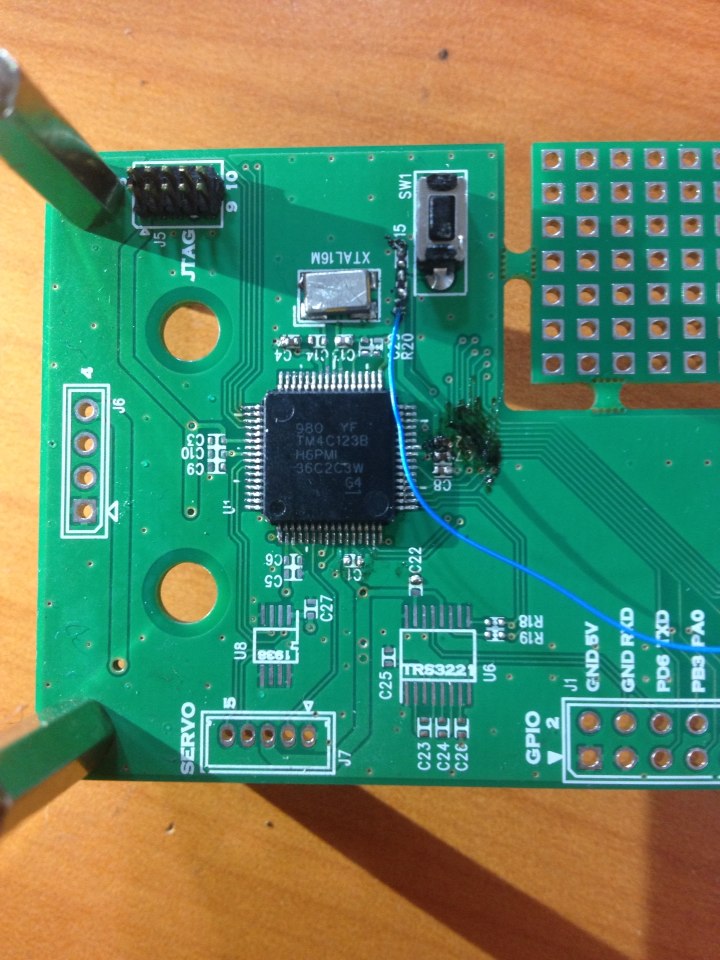
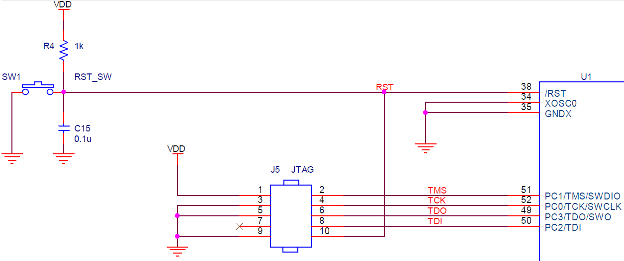
I've connected Tiva MCU TM4C123BH6PMI, Reset Switch with pull-up resistor(1k), and a 2x5(1.27mm pitch) pin headers for JTAG Debugging pins to a PCB.

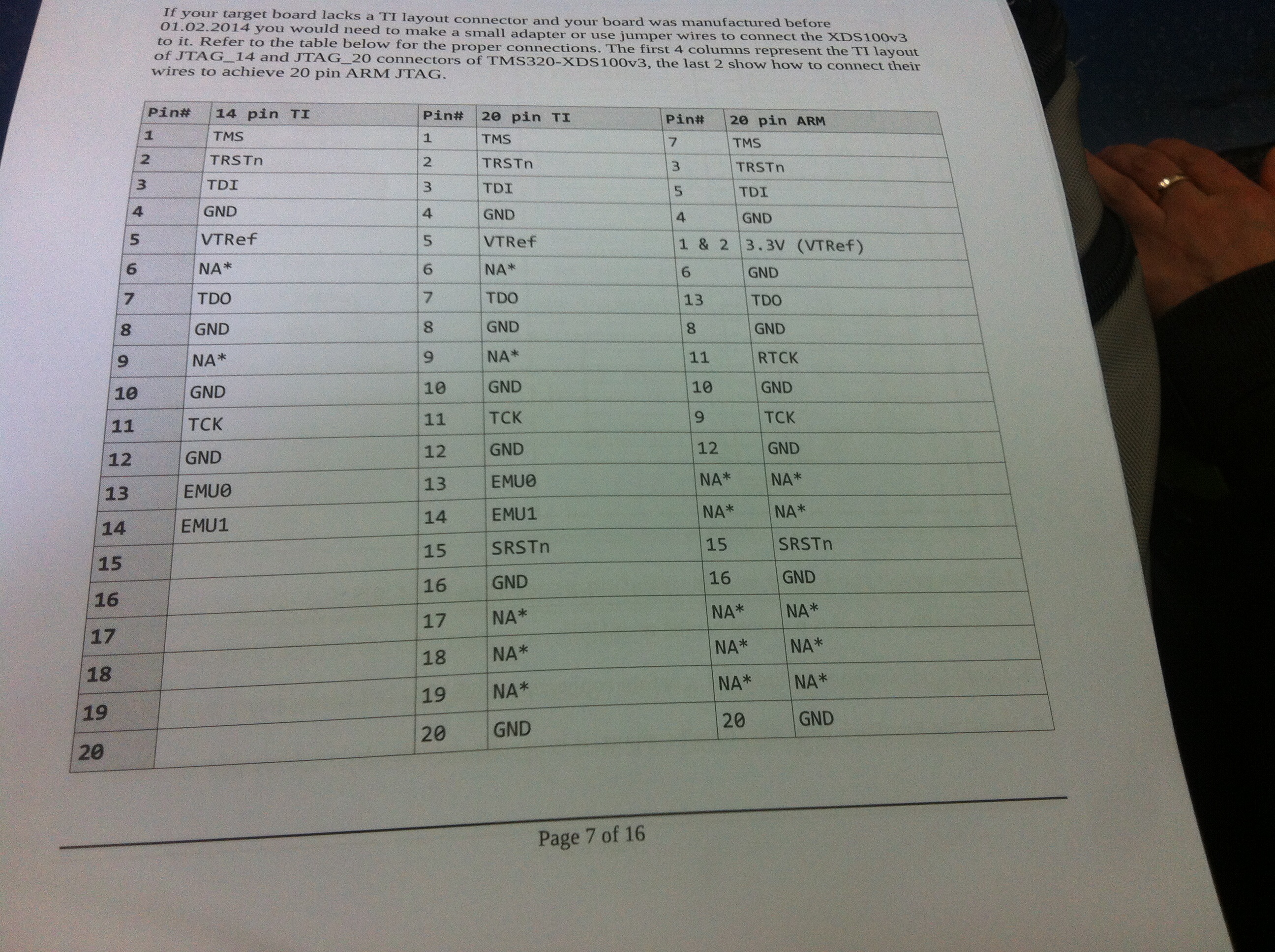
Then I used MDL-ADA2(ADAPTER MODULE 10-20PIN JTAG) to connect the 2x5 pin headers to my XDS100V3's 2x10 pins.


Building the project was successful, but errors came out so debuggings is unavailable.

The following errors was the picture below...

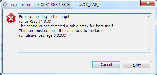
Can somebody tell what is the problem, please?? T^T

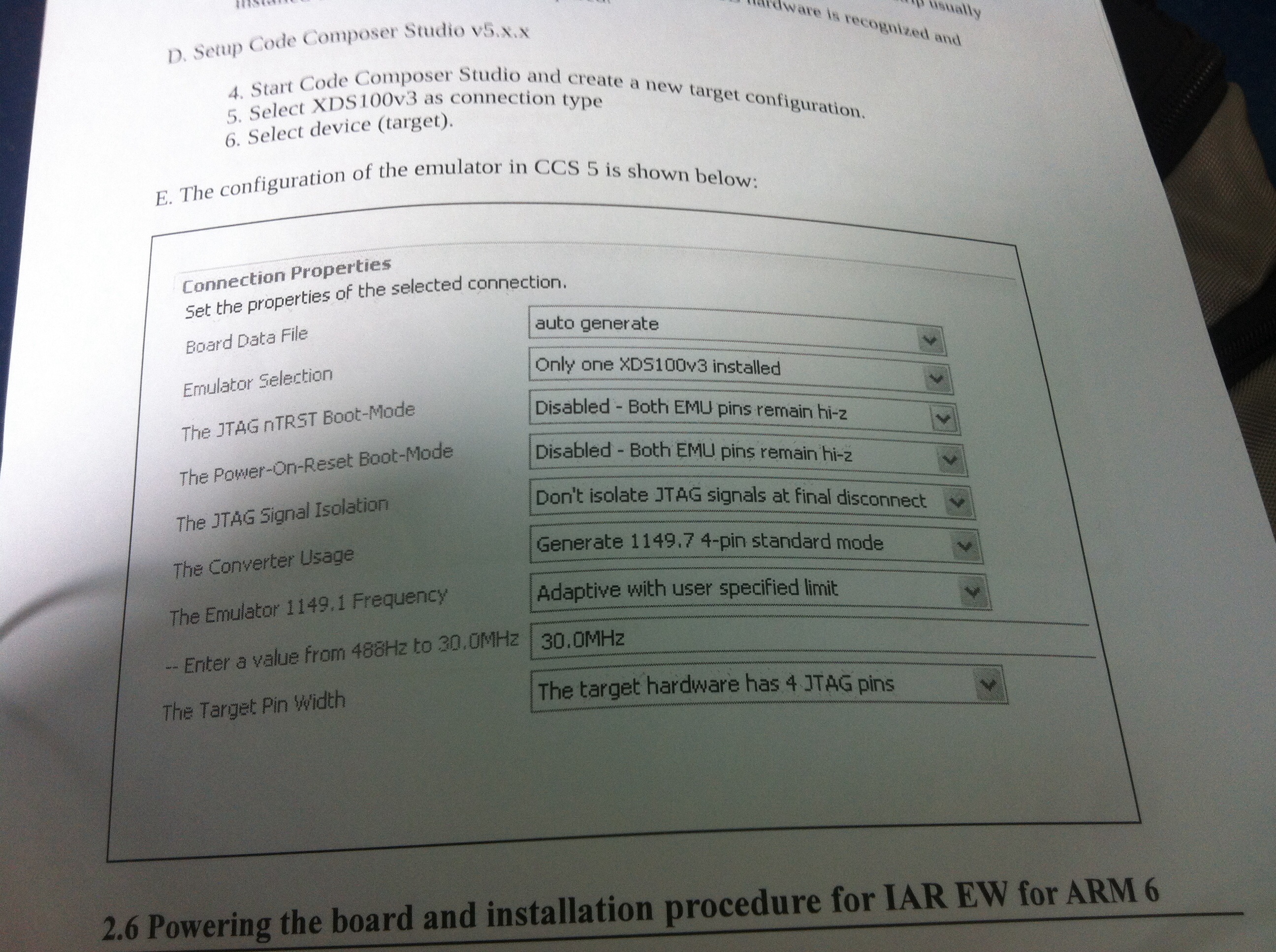
I'm using CCS5.5 at Windows7 but I didn't install EmuPack.(I actually don't know what EmuPack do..)

Is there a webpage where there's list of errors?

Is there a problem using the 10-20PIN JTAG Adapter? Or hardware soldering problems?

The project I build used the following code. (It's just a simple LED blinking code.)

#include <stdint.h>
#include "My_headers\tm4c123bh6pm.h"
/*
 * main.c
 */
int main(void) {
 
 volatile uint32_t ui32Loop;

     //
     // Enable the GPIO port that is used for the on-board LED.
     //
     SYSCTL_RCGC2_R = SYSCTL_RCGC2_GPIOF;

     //
     // Do a dummy read to insert a few cycles after enabling the peripheral.
     //
     ui32Loop = SYSCTL_RCGC2_R;

     //
     // Enable the GPIO pin for the LED (PF3).  Set the direction as output, and
     // enable the GPIO pin for digital function.
     //
     GPIO_PORTF_DIR_R = 0x08;
     GPIO_PORTF_DEN_R = 0x08;

     while(1)
        {
            //
            // Turn on the LED.
            //
            GPIO_PORTF_DATA_R |= 0x08;
            //PF3

            //
            // Delay for a bit.
            //
            for(ui32Loop = 0; ui32Loop < 200000; ui32Loop++)
            {
            }

            //
            // Turn off the LED.
            //
            GPIO_PORTF_DATA_R &= ~(0x08);

            //
            // Delay for a bit.
            //
            for(ui32Loop = 0; ui32Loop < 200000; ui32Loop++)
            {
            }
        }
}


  • Hello Min-Ku,

    Can you please specify which XDS100V3 is this as there is an option of CJTAG/JTAG and Olimex or Spectrum Digital both vendors supply by the name of XDS100V3. This will help me in isolating the pin header info.

    Secondly which DK/EK board are you using so that Pin Mapping can be made from the schematics to the Emulator.

    Looking at the error message the most probable cause may be TDIS is not GND or VTref is missing to the emulator.

    Regards

    Amit

  • Thanks for your reply.

    It's TMS320-XDS100-V3.

    Secondly, I'm not using DK/EK boards from TI. I just bought the MCU and other peripherals, chip resistors and caps.

    The picture above is a cumstom-builded board I ordered from a company.

    The MCU is TM4C123BH6PMI. I tested the Vdd with a multimeter and worked correctly(3.3V).

    The JTAG pin is connected like this.

    +)Question, I read about the TI Wiki XDS100. What is EmuPack? Is this related to these errors?

  • Hello Min-Ku,

    There are two problems here.

    1. The MDL-ADA2 is to convert between 20-Pin ARM and 10-Pin ARM. The XDS100V3 has a 14 Pin TI_JTAG and 20-Pin TI_JTAG header which is not compatible with 20-Pin ARM Header. As per the Data sheet only XDS100V3 manufactured after 01.02.2014 have an adapter to convert XDS100V3 to 20-Pin ARM Header

    2. Even if the above is resolved, there is another problem. The XDS100V3 requires Pin-4 to be GND and Pin-5 to be connected to 3.3V which I am not sure how the JTAG header in schematic will do.

    I will suggest running wires from the XDS100V3 to the JTAG Header. I am also sending the following link that can help you identify the Pin on the XDS100V3 to be used to connect to the Board. Please make sure #2 above is also done besides TCK,TMS,TDI, TDO and GND

    http://processors.wiki.ti.com/index.php/XDS_Target_Connection_Guide#Table_7._Summary:_ARM_20-pin_Header_Information

    Regards

    Amit

  • LOL, I didn't know there was TI 20 pin :) Thank you so much!

    I'm trying the wiring now.

    +) Question

    At CCS5, how can I set this configuration??

  • Hello Min-Ku,


    Do not use the Adaptive option in the "The Emulator 1149.1 Frequency" and keep the actual frequency as 1.0 MHz

    Regards

    Amit

  • Hello, and thanks again!

    1) May I ask why not using that option??

    2) Before using or not using it, how do I set that up??

    What menu do I have to go?? T^T

  • Hello Min-Ku

    1. TIVA-C does not support Adaptive Clocking.

    2. There would be a ccxml in the project. On second thoughts that is something you would have already done since the file tells what Emulator is being used, e.g XDS100V3, XDS100V2, Stellaris ICDI, etc.

    Regards

    Amit

  • Holy COW!!! IT WORKED!!!!!!!!!!!!! T^T

    Thanks Amit ~.

  • Hello Amit,

    I am trying to add a JTAG 10-pin ARM connector to my circuit too.

    Going over your answer I don't understand why you say that even if you have the updated version of the XDS100V3 that is compatible with the 20-Pin ARM Header (and using it with the MDL-ADA2 adapter) it is still necessary to have Pin-4 as ground and Pin-5 connected to 3.3V. I've looked through the link you've provided and clearly states there in the"10-ARM pin" column in the table under the chapter "JTAG header pinouts" that Pin 4 should be TCK and pin 5 should be GND.

    Any thoughts?

    Thanks,

    Eyal

  • Hello Eyal,

    That comment was meant for the 14 Pin and 20 Pin CTI headers. That is the 2nd and 3rd column pin mapping in table which is there in the li k I had provided.

    Regards
    Amit
  • Thanks for the clarification