This thread has been locked.

If you have a related question, please click the "Ask a related question" button in the top right corner. The newly created question will be automatically linked to this question.

uDMA Transfer Complete Interrupt Timing


Hello,

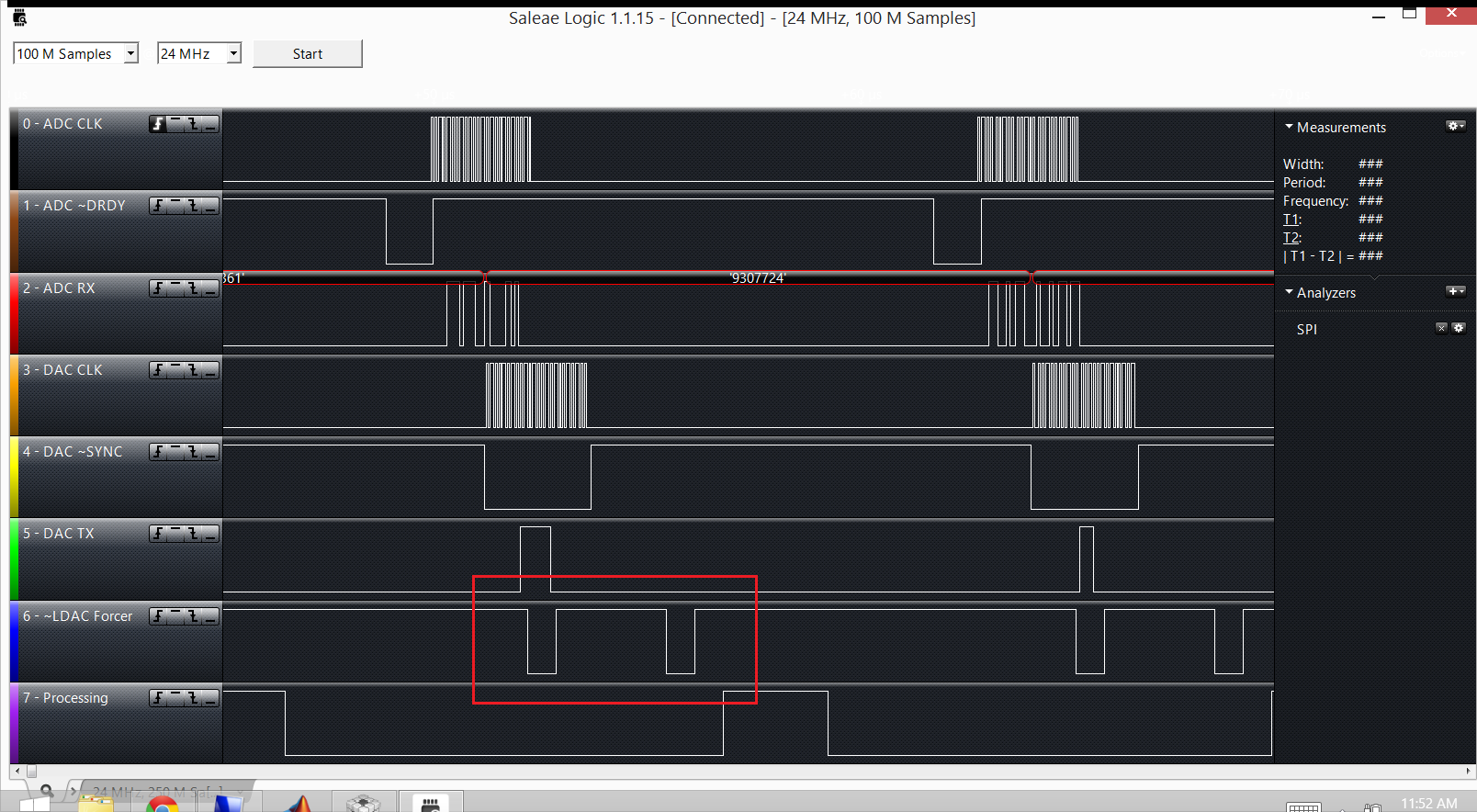
I have the uDMA setup to make a transfer to the SSI0 TX.  I also have the SSI0 end of transmission (EOT) interrupt setup to trigger a gpio pulse low.  However when I monitor the SSI0 output and the gpio using a logic analyzer I notice that it takes 2 us (CLK =80MHz) from the end of the SSI0 transmission to the start of the pulse that is triggered by the SSI0 EOT interrupt.  The Logic analyzer screenshot below shows the problem.  (also available in the attached folder) The signals in the screenshot are:

DAC CLK -> SSI 0 CLK

DAC ~SYNC -> SSI0 CS

~LDAC FORCER -> GPIO pulse supposedly generated by SSI0 EOT interrupt

I was really expecting ~LDAC_FORCER to go low immediately following the end of the SSI0 transmission.

I really appreciate any help on this one.  I've been working on it for a while now.

My code is attached:  1263.SSI0 - EOT Interrupt Issue - code.zip

Thanks,

Curtis

  • Hello Curtis,

    In the interrupt handler, I do not see a clear function for clearing the interrupt source.

    Also please check the DMA section in SSI Chapter of the spec. When DMA is used then DMADONE interrupt is on the SSI Interrupt Line and not the SSI Interrupt. So what you are seeing is the DMADONE interrupt and not the EOT interrupt.

    Regards

    Amit

  • Hey Amit,

    Do I need to clear the interrupt?  From page 599 of the device datasheet: "The completion interrupt request from the μDMA controller is automatically cleared when the interrupt handler is activated."

    I had considered previously that it was probably the DMADONE interrupt.  If that's the case though I would expect the interrupt to complete even earlier than the EOT interrupt.  The uDMA should finish transfering data to the SSI before the SSI finishes transmitting the data placed in the SSI FIFO by the uDMA.

    So, assuming that you're right and it is the DMADONE interrupt, the problem of why the interrupt takes so long to assert is still an issue.

    Thanks,

    Curtis

  • Hello Curtis,

    Yes, you are correct. Entry in the ISR would clear that. And the interrupt handler is fired when a DMADONE comes as an enable channel will block peripheral interrupt.

    I am not able to run the code you have in my setup. So what I will do is to have a simple code of SSI and DMA in Auto mode (normally I use Peripheral Request instead of AUTO) and check the delay. Normally I have seen this to be few clock cycle as my system load is way too less.

    Regards

    Amit

  • Hey Amit,

    I have changed my code to enable the uDMA interrupt that for triggers at the end of software uDMA transfers during my initialization of the SSI0 uDMA.

    uDMAChannelAttributeEnable(UDMA_CHANNEL_SSI0TX, UDMA_ATTR_REQMASK);
    	// Now the software channel is primed to start a transfer.  The channel
    	// must be enabled.  For software based transfers, a request must be
    	// issued.  After this, the uDMA memory transfer begins.
    	uDMAChannelEnable(UDMA_CHANNEL_SSI0TX);
    	IntEnable(INT_UDMA); // Enables the Software channel interrupt that triggers
    						   // upon completion of a software transfer.

    The ISR for this interrupt just pulses ~LDAC_FORCER low.  As seen in the the logic analyzer plot below, the uDMA ISR triggers once at the end of the uDMA transfer and then the SSI0 ISR triggers much later.  The part of the plot highlighted below shows that both IDRs are triggered at different times.  I confirmed using the debugger that the first one is the uDMA ISR and the second one is the SSI0 interrupt.

    Here is the code that generated the above result: 2541.SSI0 - EOT Interrupt Issue - code 2.zip

    Should both of those interrupts trigger due to the uDMA transfer completion?  Do you still think the SSI0 ISR is triggered by the uDMA transfer completion?

    Regards,

    Curtis

  • Hello Curtis,

    Now that requires investigation. I will need to run a code on my side to be able to duplicate what you are seeing.

    When the second ISR fires, can you please take a register dump of SSI peripheral.

    Regards

    Amit

  • Hey Amit,

    Let me know if there is anything else I can do to assist you.

    Here is the register dump

    I also tried not enabling the SSI0 uDMA bt 

    Memory Addresses 0x40008000 through 0x40008024 (SSI0 Registers):

    00000387 00000012 00000000 00000007 00000002 00000008 00000007 00000000 00000000
    00000003

    Regards,

    Curtis

  • Hello Curtis,

    The register dump looks fine except that there is a RORRIS bit set (receiver over-run). Secondly, even with the UDMA not enabled the EOT interrupt comes after 2us?

    Regards

    Amit

  • Hey Amit,

    Yeah, whether or not the SSI0 uDMA is enabled the functionaality is the same with the SSI0 interrupt (second interrupt) triggering both when I have enabled the SSI0 uDMA and when I haven't.

    -Curtis

  • Hey Amit,

    I only use SSI0 to transmit so I never remove data from the RX FIFO.  Is there any reason I need to clear the RX FIFO after each transmission?

    Thanks,

    Curtis

  • Hello Curtis,

    I was thinking the same. Normally when data is pushed out on TX line, the RX line is also sampled and put in the FIFO. This must be removed to prevent any unwanted error from getting asserted.

    Also on closer inspection (the font size on my browser was small) I see that the RTRIS, RXRIS and RORIS all are set. Out of this the RTRIS and RORIS are error interrupt sources and I am thinking this may be asserting the error interrupt path.

    Regards

    Amit

  • Hey Amit,

    I added the following piece of code to the start of the while(1) loop in my main function, after the DAC_g_dataReady flag check and found that emptying the RX FIFO between each transmit didn't help.  I still see the same thing.

    uint32_t trashBin[1];
    while(SSIDataGetNonBlocking(SSI0_BASE, &trashBin[0])) {
    }

    Regards,

    Curtis

  • Hey Amit,

    I tried switching the uDMA channel used from UDMA_CHANNEL_SSI0TX to UDMA_CHANNEL_SW but I am seeing the same issue.

    Regards,

    Curtis

  • Hello Curtis

    Appreciate the string of experiments and quick results. I would need time to get the same working on my side so that I can reproduce the issue in my setup. I will run the code by you.

    Regards

    Amit

  • Hey Amit,

    I've continued to try a number of things, still without much success.  

    Could it be some type of conflict between the SSI or the uDMA and the processor over a bus?

    Let me know if you have any ideas.

    Thanks,

    Curtis

  • Hello Curtis,

    There bandwidth on the bus is sufficient to handle uDMA and Processor. The only thing that restricts the Processor from servicing the ISR is that it is already in some other ISR.

    My experiments are running, and so far no luck in reproducing the issue.

    Regards

    Amit

  • Hey Amit,

    Yeah, I kind of figured as much.  I just haven't come up with a good explanation yet.

    Let me know if you need my help with the experiments.  I could take a look at the test code if you want.

    Thanks,

    Curtis

  • Hey Amit,

    Is there anyone else either you or I could ask about this problem?  Or perhaps another place on this forum or another forum I should post this issue?  I really need to make some progress on this issue soon.

    Also, if you have any suggestions for a work around that would be great.  I've tried disabling the uDMA to get the EOT interrupt to not be masked by the uDMA and then reenabling it again after it triggers but that didn't work.  I also tried polling the data buffers to see if they changed value, but that also didn't work.

    All I need is to be able to set that flag at the end of the ADC trsnamission or have some other way to detect that the data in the ADC buffers has been updated so that I can run my processing code in the main function as soon as new data is available.

    Regards,

    Curtis

  • Hello Curtis,

    I thought it was DAC transmission and not the ADC transmission which was linked to the GPIO Toggle happening late?

    This is a TIVA peripheral issue so this is the only forum. However the community members may be able to help (there is a compulsory off on a Monday this week, so won;t be able to be back with my setup till Tuesday)

    Regards

    Amit

  • Hey Amit,

    Thanks for the prompt reply.

    It is happening with both the DAC and ADC interrupts.  They both show significant delays and appear to be exactly the same issue.  The ADC delay can be seen from the period between the end of the ADC transmission and when the processing indicator goes high.  

    The problem with the ADC interrupt is actually a bigger problem because I need to have as much time as possible to process the data through some CMSIS DSP operations.

    That's unfortunate for my project schedule, I'll keep trying to work it out on my own in the meantime.

    How do I keep the uDMA from masking the SSI interrupt?  If I have the SSI uDMA disabled will that allow the normal SSI interrupts to make it to the processor?  I'm trying to figure out what I need to disable in the SW uDMA complete interrupt that triggers before the end of the transmission in order to allow the EOT interrupt to trigger.

    Regards,

    Curtis

  • Hello Curtis,

    You will have to not use the uDMA. When the uDMA is enabled then it takes over the Peripheral Interrupt and masks all interrupts coming from the Peripheral till the uDMA channel interrupt is not cleared and uDMA channel disabled.

    For the meantime I would ask you to remove uDMA and rather rely on the CPU doing the data transfers.

    Regards

    Amit

  • Hey Amit,

    I wanted to get an idea of the timing of each of my interrupts so I went through each interrupt and programmed it to set the processing signal (seen in the screenshot of the original post) high at the start of the interrupt and then low again at the end of the interrupt.

    I was able to generate the following interrupt timing diagram: (also attached: 6232.Interrupt TIming.pdf )

    Since my interrupts were taking much longer than I initially anticipated I decide to directly set the registers that were previously being set using function calls from the driver library.

    However the direct register access replacement for the following call keeps going into a hard fault (FaultISR) whenever I try to read from the DMACTLBASE register to get the address of the DMA control table.

    /* Code to be replaced
    uDMAChannelTransferSet(UDMA_CHANNEL_SSI2RX | UDMA_PRI_SELECT,
    UDMA_MODE_BASIC,
    (void *)(SSI2_BASE + SSI_O_DR), ADC_g_dataBufferBytes,
    3);
    */

    uint32_t Addr;
    // All of these lines hard fault
    //Addr = (UDMA_CTLBASE_R >> UDMA_CTLBASE_ADDR_S) + (UDMA_CHANNEL_SSI2RX << 4) + UDMA_CHCTL;
    Addr = HWREG(0x400FF008);
    Addr = UDMA_CTLBASE_R;
    HWREG(HWREG(0x400FF008) + (UDMA_CHANNEL_SSI2RX << 4) + UDMA_CHCTL) |= (UDMA_CHCTL_XFERMODE_BASIC | (((3-1) << UDMA_CHCTL_XFERSIZE_S) & UDMA_CHCTL_XFERSIZE_M));
    HWREG(UDMA_CTLBASE_R + (UDMA_CHANNEL_SSI2RX << 4) + UDMA_CHCTL) |= (UDMA_CHCTL_XFERMODE_BASIC | (((3-1) << UDMA_CHCTL_XFERSIZE_S) & UDMA_CHCTL_XFERSIZE_M));

    Any idea why it faults each time I try to access the DMACTLBASE register?

    Regards,
    Curtis

  • Hello Curtis,

    Please do make sure that the SYSCTL.RCGCDMA register bit is set to 1 and SYSCTL.PRDMA bit is 1 as well before accessing the register of UDMA. Other than that there is no other reason why it may give a Bus Fault/

    Regards

    Amit

  • Hey Amit,

    I just checked both those bits and they are both set right before executing the line that is faulting.  So I'm not sure what is going wrong when trying to access that register.

    -Curtis

  • Hello Curtis,

    Now that is wierd. Are you able to access the UDMA Address Space via the debugger memory window or does it show something like "-" pr "?". I haven't seen such an issue of PP and RCGC bits are set.

    Also do check the fault registers 0xE000ED28 and 0xE000ED38. That would give me some additional pointers.

    I will be sending across a set of tests based on your code to check th EOT timing so that you can double check the 2us delay.

    Regards

    Amit

  • Hey Amit,

    Actually I figured out that problem.  It was actually the line before it that was the problem and for whatever reason the fault wasn't happening until after the next line that I originally thought was causing the problem.  The line that was causing the problem was to set the GPIO data high so I could track the length of the interrupt:

    HWREG(0x4005A000 +(0x80 <<2)) = 0x80; // Write high to GPIO PC7

    Changing it to the following helped to solve the fault:

    HWREG(GPIO_PORTC_BASE + GPIO_O_DATA + (0x80 <<2)) = 0x80; // Write high to GPIO PC7

    I'm still not sure why I can't use the advanced high performance bus (AHB) and had to use the APB.


    From the datasheet:

    Table 10-6 on page 658 lists the GPIO registers. Each GPIO port can be accessed through one of
    two bus apertures. The legacy aperture, the Advanced Peripheral Bus (APB), is backwards-compatible
    with previous devices. The other aperture, the Advanced High-Performance Bus (AHB), offers the
    same register map but provides better back-to-back access performance than the APB bus.

    ■ GPIO Port C (APB): 0x4000.6000
    ■ GPIO Port C (AHB): 0x4005.A000

    Why can't I use the AHB without it faulting?

    I look forward to taking a look at your test benches tomorrow.

    Regards,

    Curtis

  • Curtis Mayberry1 said:
    Why can't I use the AHB without it faulting?

    Likely because you've not first, "SystemCtlPeripheralEnabled" that AHB bus?

  • Hello Curtis,

    You need to call the following for AHB Map to be opened.

    SysCtlGPIOAHBEnable(SYSCTL_PERIPH_GPIOC)

    Regards

    Amit