This thread has been locked.

If you have a related question, please click the "Ask a related question" button in the top right corner. The newly created question will be automatically linked to this question.

Tiva tm4c123 launchpad I2C transmission

Hello,

i got problem with transmission between tiva and mpl3115a2 sensor. My code:

GPIOPinTypeGPIOInput(GPIO_PORTA_BASE, GPIO_PIN_6 | GPIO_PIN_7);

// GPIOPadConfigSet( GPIO_PORTA_BASE, GPIO_PIN_6 | GPIO_PIN_7, GPIO_STRENGTH_2MA, GPIO_PIN_TYPE_OD_WPU);
SysCtlPeripheralEnable(SYSCTL_PERIPH_GPIOA);

GPIOPinTypeI2CSCL(GPIO_PORTA_BASE, GPIO_PIN_6); // special I2CSCL treatment for M4F devices
GPIOPinTypeI2C(GPIO_PORTA_BASE, GPIO_PIN_7);

GPIOPinConfigure(GPIO_PA6_I2C1SCL);
GPIOPinConfigure(GPIO_PA7_I2C1SDA);

SysCtlPeripheralEnable( SYSCTL_PERIPH_I2C1);

I2CMasterInitExpClk(I2C1_BASE, SysCtlClockGet(), false);
SysCtlDelay(10000);

and function that i use for read:

void i2c_sent_read(char addre, unsigned long data,unsigned long *receive){
unsigned long k=0;
I2CMasterSlaveAddrSet(I2C1_BASE,addre,true);
I2CMasterDataPut(I2C1_BASE,data);
I2CMasterControl(I2C1_BASE,I2C_MASTER_CMD_SINGLE_RECEIVE);
while(I2CMasterBusy(I2C1_BASE)){}
//I2CMasterControl(I2C1_BASE,I2C_MASTER_CMD_SINGLE_RECEIVE);
while(I2CMasterBusy(I2C1_BASE)){}
k=I2CMasterErr(I2C1_BASE);

*receive=I2CMasterDataGet(I2C1_BASE);

}

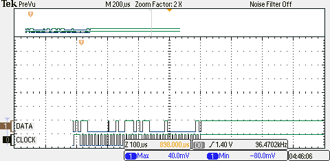
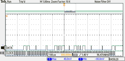
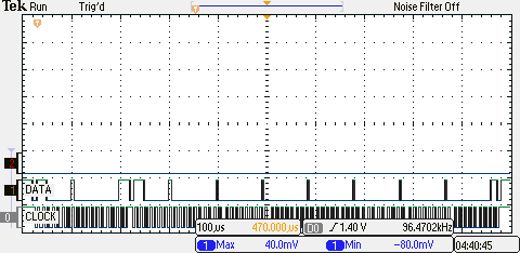
Result: i read error value 4 (I2C_MASTER_ERR_ADDR_ACK), and value that i read from buffer is 255. I can't read anything from sensor. 

Thanks for help

  • Hello Matthew,

    Are you sure that the Slave Address that you have put as part of the I2CMasterSlaveAddrSet matches the Address that the Slave device is expecting? The I2C_MASTER_ADDR_ACK basically indicates that the Slave has not acknowledged the Slave Address sent by the master as it does not match what it believes to be it's encoded address. You may want to look at the specification of mpl3115a2 device for I2C Slave Address Decoding/

    Regards

    Amit

  • Hello Matthew,

    A couple of things to note.

    You should not be accessing a peripheral prior to enabling the clock through the SysCtl.  You should remove the GPIOInput declaration for the GPIO A pins prior to this call.

    There are two successive waits for the busy bit.  I believe there should only be one.

    The return err is indicating that the slave address is not correct.  The sensor slave address is 0x60.  Are you setting the slave address correctly in the code?  

    Hope that helps.

    -c


  • Thank you. I removed from code line GPIOPinTypeGPIOInput(GPIO_PORTA_BASE, GPIO_PIN_6 | GPIO_PIN_7);

    Right now the slave address that i use is 0x60, by my mistake i typed 0x66 now there is no error. I wanted to read for example 0x0C register, but still with no result.

  • Hello Matthew,

    A code post would be useful.

    Regards

    Amit


  • #include <stdint.h>
    #include <stdbool.h>
    #include "inc/hw_memmap.h"
    #include "inc/hw_types.h"
    #include "driverlib/debug.h"
    #include "driverlib/fpu.h"
    #include "driverlib/gpio.h"
    #include "driverlib/pin_map.h"
    #include "driverlib/rom.h"
    #include "driverlib/sysctl.h"
    #include "driverlib/uart.h"
    #include "utils/uartstdio.h"
    #include "i2c_protocol_setup_operate.h"

    //*****************************************************************************
    //
    //! \addtogroup example_list
    //! <h1>Hello World (hello)</h1>
    //!
    //! A very simple ``hello world'' example. It simply displays ``Hello World!''
    //! on the UART and is a starting point for more complicated applications.
    //!
    //! UART0, connected to the Virtual Serial Port and running at
    //! 115,200, 8-N-1, is used to display messages from this application.
    //
    //*****************************************************************************


    //*****************************************************************************
    //
    // The error routine that is called if the driver library encounters an error.
    //
    //*****************************************************************************
    #ifdef DEBUG
    void
    __error__(char *pcFilename, uint32_t ui32Line)
    {
    }
    #endif

    //*****************************************************************************
    //
    // Configure the UART and its pins. This must be called before UARTprintf().
    //
    //*****************************************************************************
    void
    ConfigureUART(void)
    {
    //
    // Enable the GPIO Peripheral used by the UART.
    //
    ROM_SysCtlPeripheralEnable(SYSCTL_PERIPH_GPIOA);

    //
    // Enable UART0
    //
    ROM_SysCtlPeripheralEnable(SYSCTL_PERIPH_UART0);

    //
    // Configure GPIO Pins for UART mode.
    //
    ROM_GPIOPinConfigure(GPIO_PA0_U0RX);
    ROM_GPIOPinConfigure(GPIO_PA1_U0TX);
    ROM_GPIOPinTypeUART(GPIO_PORTA_BASE, GPIO_PIN_0 | GPIO_PIN_1);

    //
    // Use the internal 16MHz oscillator as the UART clock source.
    //
    UARTClockSourceSet(UART0_BASE, UART_CLOCK_PIOSC);

    //
    // Initialize the UART for console I/O.
    //
    UARTStdioConfig(0, 115200, 16000000);
    }

    //*****************************************************************************
    //
    // Print "Hello World!" to the UART on the evaluation board.
    //
    //*****************************************************************************
    int
    main(void)
    {
    //volatile uint32_t ui32Loop;

    //
    // Enable lazy stacking for interrupt handlers. This allows floating-point
    // instructions to be used within interrupt handlers, but at the expense of
    // extra stack usage.
    //
    ROM_FPULazyStackingEnable();

    //
    // Set the clocking to run directly from the crystal.
    //
    ROM_SysCtlClockSet(SYSCTL_SYSDIV_4 | SYSCTL_USE_PLL | SYSCTL_XTAL_16MHZ |
    SYSCTL_OSC_MAIN);

    //
    // Enable the GPIO port that is used for the on-board LED.
    //
    ROM_SysCtlPeripheralEnable(SYSCTL_PERIPH_GPIOF);

    //
    // Enable the GPIO pins for the LED (PF2 & PF3).
    //
    ROM_GPIOPinTypeGPIOOutput(GPIO_PORTF_BASE, GPIO_PIN_2);

    //
    // Initialize the UART.
    //
    ConfigureUART();

    //
    // Hello!
    //
    UARTprintf("test");
    i2c_setup();
    unsigned long k=0;
    // Loop Forever
    UARTprintf("test\n");

    SysCtlDelay(2000000);
    while(1)
    {
    //
    // Turn on the LED
    i2c_sent_read(0x60,0x0C, &k);
    //GPIOPinWrite(GPIO_PORTF_BASE, RED_LED|BLUE_LED|GREEN_LED, RED_LED);

    UARTprintf("\033[2Jvalue=%d",k);
    //
    GPIOPinWrite(GPIO_PORTF_BASE, GPIO_PIN_2, GPIO_PIN_2);

    //
    // Delay for a bit.
    //
    SysCtlDelay(SysCtlClockGet() / 10 / 3);

    //
    // Turn off the BLUE LED.
    //
    GPIOPinWrite(GPIO_PORTF_BASE, GPIO_PIN_2, 0);

    //
    // Delay for a bit.
    //
    SysCtlDelay(SysCtlClockGet() / 10 / 3);
    }
    }

    ///////////////////////////////////////////////// i2c_protocol_setup_operate.c///////////////////////////

    #include <stdbool.h>
    #include <stdint.h>
    #include "inc/hw_i2c.h"
    #include "inc/hw_memmap.h"
    #include "inc/hw_types.h"

    #include "driverlib/gpio.h"
    #include "driverlib/i2c.h"
    #include "driverlib/pin_map.h"
    #include "driverlib/sysctl.h"
    #include "driverlib/uart.h"
    #include "utils/uartstdio.h"

    void i2c_setup(void){

    SysCtlPeripheralEnable(SYSCTL_PERIPH_GPIOA);

    GPIOPinTypeI2CSCL(GPIO_PORTA_BASE, GPIO_PIN_6); // special I2CSCL treatment for M4F devices
    GPIOPinTypeI2C(GPIO_PORTA_BASE, GPIO_PIN_7);

    GPIOPinConfigure(GPIO_PA6_I2C1SCL);
    GPIOPinConfigure(GPIO_PA7_I2C1SDA);

    SysCtlPeripheralEnable( SYSCTL_PERIPH_I2C1);

    I2CMasterInitExpClk(I2C1_BASE, SysCtlClockGet(), false);
    SysCtlDelay(10000);
    }

    void i2c_sent_read(char addre, unsigned long data,unsigned long *receive){
    unsigned long k=0;
    I2CMasterSlaveAddrSet(I2C1_BASE,addre,true);
    I2CMasterDataPut(I2C1_BASE,data);
    I2CMasterControl(I2C1_BASE,I2C_MASTER_CMD_SINGLE_RECEIVE);
    while(I2CMasterBusy(I2C1_BASE)){}
    //I2CMasterControl(I2C1_BASE,I2C_MASTER_CMD_SINGLE_RECEIVE);
    //while(I2CMasterBusy(I2C1_BASE)){}
    k=I2CMasterErr(I2C1_BASE);

    k=I2CMasterDataGet(I2C1_BASE);
    *receive=k;

    }

  • Hello Matthew,

    The slave device datasheet is unfortunately not very explicit in the I2C Transaction model. But based on similar devices and arduino example the sequence should be as follows

    //

    // Write the address first with direction as transmit to write the address for read

    //

    I2CMasterSlaveAddrSet(I2C1_BASE,addre,false);

    I2CMasterDataPut(I2C1_BASE,data);

    I2CMasterControl(I2C1_BASE,I2C_MASTER_CMD_BURST_SEND_START);

    while(!I2CMasterBusy(I2C1_BASE));

    while(I2CMasterBusy(I2C1_BASE));

    //

    // Repeated Start now with direction as recieve can be used to get data

    //

    I2CMasterSlaveAddrSet(I2C1_BASE,addre,true);

    I2CMasterControl(I2C1_BASE,I2C_MASTER_CMD_SINGLE_RECEIVE);

    while(!I2CMasterBusy(I2C1_BASE));

    while(I2CMasterBusy(I2C1_BASE));

    k=I2CMasterErr(I2C1_BASE);

    k=I2CMasterDataGet(I2C1_BASE);

    *recieve=k;

    Regards

    Amit

  • Edit

    Thank you for fast answer. Now it works! Could you explain why did you use I2CMasterControl(I2C1_BASE,I2C_MASTER_CMD_BURST_SEND_START); and I2CMasterControl(I2C1_BASE,I2C_MASTER_CMD_SINGLE_RECEIVE); 

    not only I2CMasterControl(I2C1_BASE,I2C_MASTER_CMD_SINGLE_RECEIVE);?


    Thx

  • Hello Matthew

    The Slave device after being addressed needs to be told which register needs to be accessed. This value has to be written to the Slave device hence SEND_START.

    Once done the Slave device has to be read by the master and hence the SINGLE_RECEIVE which will issue a repeated start with the slave address following which the Master will release the SDA to slave to drive.

    Good to hear that it works now!!!

    Regards

    Amit

  • Hello, 

    i got problem with my code during testing. I made few functions for sigle and multiple read. I tested it and it was working fine. Then i move forward and add timer. Timer was also tested if it works ok by turning on diode in interupt routine and turning it off  in main loop. Then I add  single read to timer(works) and then multiread and it's not working - with this combination ( multiread in timer routine) single read is not working in main loop. So i remove i2c read function form timer and try to read i2c line in main loop without possitive result. During debugging first time i got error 0x10 I2C_MASTER_ERR_ARB_LOST 0x00000010, so i reset program and started debugging again, and there was no error (strange) and i cant read data form sensor again. Please look at the function below, maybe you will find that thing that i can;t see for now. For me it's very strange situtation because previously this function was working fine, but after i put it to timer service routine it stoped working and all program is not working. Also i attached all my project form workspace. Thank you for you help

    extern void i2c_multi_read(char address, unsigned data, unsigned repeat, volatile short tab[] ){
    unsigned long k=0,err=0,i=0;
    I2CMasterSlaveAddrSet(I2C1_BASE,address,true); //false
    I2CMasterDataPut(I2C1_BASE,data);
    I2CMasterControl(I2C1_BASE,I2C_MASTER_CMD_BURST_SEND_START);
    while(!I2CMasterBusy(I2C1_BASE));

    while(I2CMasterBusy(I2C1_BASE));
    I2CMasterSlaveAddrSet(I2C1_BASE,address,true);

    I2CMasterControl(I2C1_BASE,I2C_MASTER_CMD_BURST_RECEIVE_START );

    while(!I2CMasterBusy(I2C1_BASE));

    while(I2CMasterBusy(I2C1_BASE));
    tab[0]=I2CMasterDataGet(I2C1_BASE);//no dummy read - 1st read
    tab[5]=I2CMasterErr(I2C1_BASE);
    for(i=0;i<repeat;i++){
    I2CMasterControl(I2C1_BASE,I2C_MASTER_CMD_BURST_RECEIVE_CONT);
    //err=I2CMasterErr(I2C1_BASE);
    while(!I2CMasterBusy(I2C1_BASE));
    while(I2CMasterBusy(I2C1_BASE));

    tab[i+1]=I2CMasterDataGet(I2C1_BASE);

    if (I2CMasterErr(I2C1_BASE)!=0){tab[5]=I2CMasterErr(I2C1_BASE);}
    }

    I2CMasterControl(I2C1_BASE,I2C_MASTER_CMD_BURST_RECEIVE_FINISH);


    }

    6332.hello_tmc.rar

  • Hello Matthew,

    If you are doing I2C reads in the Timer ISR and in the Main loop, then I would suggest to remove the Main Loop reads. It may be causing contention from I2C programming.

    I do not have the sensor as you mentioned so it would not be possible for me to debug the code.

    Regards

    Amit

  • Hello,

    i did it, still nothing. Now i got empty timer isr (only with diode) and function with single read in main loop. I'm trying to read all registers separetly. during every read i receive error - arb_lost. Could you check for me if my project is well setup ? 

  • Hi,

    Finaly i found that while(!I2CMasterBusy(I2C1_BASE)); may cause the problem. Still i got problem with signle read and multread outside main loop, and i have no idea what is going on. when i move out my function to Timer ISR or GPIO ISR i got error 0x10 which means arbitration lost. I took code form my function and put it inside GPIO ISR routine and in the main loop: i am able to read data when i'm in main loop, reading data from GPIO ISR (timer too) is imposible i got only error 0x10. Can you give me any suggestions?

    extern void i2c_multi_read(char address, unsigned data, unsigned repeat, volatile short tab[] ){
    unsigned long k=0,err=0,i=0;
    I2CMasterSlaveAddrSet(I2C1_BASE,address,true); //false
    I2CMasterDataPut(I2C1_BASE,data);
    I2CMasterControl(I2C1_BASE,I2C_MASTER_CMD_BURST_SEND_START);
    while(!I2CMasterBusy(I2C1_BASE));

    while(I2CMasterBusy(I2C1_BASE));
    I2CMasterSlaveAddrSet(I2C1_BASE,address,true);

    I2CMasterControl(I2C1_BASE,I2C_MASTER_CMD_BURST_RECEIVE_START );

    while(!I2CMasterBusy(I2C1_BASE));

    while(I2CMasterBusy(I2C1_BASE));
    tab[0]=I2CMasterDataGet(I2C1_BASE);//no dummy read - 1st read
    tab[5]=I2CMasterErr(I2C1_BASE);
    for(i=0;i<repeat;i++){
    I2CMasterControl(I2C1_BASE,I2C_MASTER_CMD_BURST_RECEIVE_CONT);
    //err=I2CMasterErr(I2C1_BASE);
    while(!I2CMasterBusy(I2C1_BASE));
    while(I2CMasterBusy(I2C1_BASE));

    tab[i+1]=I2CMasterDataGet(I2C1_BASE);

    if (I2CMasterErr(I2C1_BASE)!=0){tab[5]=I2CMasterErr(I2C1_BASE);}
    }

    I2CMasterControl(I2C1_BASE,I2C_MASTER_CMD_BURST_RECEIVE_FINISH);


    }

    Same situation is with code posted by Ashira, i'm able to read data from sensor in main loop only. 

    I2CMasterSlaveAddrSet(I2C1_BASE,addre,false);

    I2CMasterDataPut(I2C1_BASE,data);

    I2CMasterControl(I2C1_BASE,I2C_MASTER_CMD_BURST_SEND_START);

    while(!I2CMasterBusy(I2C1_BASE));

    while(I2CMasterBusy(I2C1_BASE));

    //

    // Repeated Start now with direction as recieve can be used to get data

    //

    I2CMasterSlaveAddrSet(I2C1_BASE,addre,true);

    I2CMasterControl(I2C1_BASE,I2C_MASTER_CMD_SINGLE_RECEIVE);

    while(!I2CMasterBusy(I2C1_BASE));

    while(I2CMasterBusy(I2C1_BASE));

    k=I2CMasterErr(I2C1_BASE);

    k=I2CMasterDataGet(I2C1_BASE);

    *recieve=k;

  • Hello Matthew,

    I see there are two functions: i2c_read and i2c_multi_read. I would want to clarify the following from you

    1. Do both function cause an issue or only one of them cause an issue?

    2. Which of the two function cause an issue in GPIO_ISR alone

    3. Which of the two function cause an issue in TIMER_ISR alone

    4. Which of the two function cause an issue in main

    5. If instead of using the function you use the full code in main or GPIO_ISR or TIMER_ISR then does it work?

    Regards

    Amit

  • Hello,

    1. Two functions cause an issue.

    2. Both function cause an issue in GPIO_ISR i got error nr 0x18

    3. Both too. error 0x18 too.

    4. In main working both was working fine

    5. Yes i put full code of function i2c_read (works) then move it to both ISR and was not working.

  • Hello Matthew,

    The code looks fine and no such visible issue as such.As long the I2C Transaction are happening in only one place (either Timer ISR or main) it should be good.

    Also the Timer is set for 250ms Timeout which should give sufficient time for the I2C Processing to happen.

    Also is the issue happening on the very first Timer ISR or after some time (can this some time is fixed). Can you probe the I2C Bus to see what is happening?

    Regards

    Amit

  • Hello Amit,

    ok i will sent osciloscope screen when it will be possible,

    I've tried to test the code once again. Here's what i did:

    remove timer  and gpio isr , setup of timer & gpio interupt from code.

    Run single read and multiread in main loop - works. So then i turned on timer with the same settings, and tried to read sensor from main loop, in timer isr -  i only clear int flag.  I asked sensor for it's id - respond was ok, then i write to sensor value i read it - value is ok. I did small change in the code - i moved timer setup code before sensor is setup. Then i add signle read function to timer and it works - so it was possible that  before sensor was setup timer was trigered and caused 0x10 error. I'm going to test gpio interupt next. 

  • Hello Amit, 

    i'm sending scope screen if you will need i can send you csv files also.

    I moved back to TIMER ISR and multiread. i can't read (multiread) anything from sensor when i trun launchpad on. Screen below is presenting what's happening on bus during read in timer isr

    So then i run CCs studio in debug mode and debug code - here single read to check if read value is right

    Next i let program to run in debug mode, stop for i while and i can see that sensor is being read (rigth values in registers). Next i exit debug mode and check if the sensor works- everytihng is fine, i can see on scope that its working and also i receive right values in uart. Below is some part of transmission


    Then i reset uC and it stops working - values i recived in uart are 0's, and on scope i can see this (1st posted  image)

  • Hello Matthew,

    I would suggest putting a GPIO to toggle high in the Timer ISR so that you can use it to capture the first set of I2C transactions. Looking at the scope capture it seems that there is something very early on that causes  Address to be NACK-ed by the slave.

    Regards

    Amit

  • Hello Matthew,

    We would need a zoomed in scope plot of the I2C Address Phase when being run in Timer ISR.

    Regards

    Amit

  • Hi Matthew,

    Would it be possible for you to share your code for MPL 3115A2 ? I too have trouble interfacing this sensor with the Tiva C.