This thread has been locked.

If you have a related question, please click the "Ask a related question" button in the top right corner. The newly created question will be automatically linked to this question.

EK-TM4C1294xl ADC0-SS0 enabled (ADCTriggerProcessor) breaks TCP packet exchanges.

Guru 55913 points

Depending where the ADC0 priority 0 and SS0-0 CTL_IE is enabled in program flow (eth_client_lwip.c) may hang during DHCP acquire address or otherwise return an IP address but not reply to ICMP ping requests. Eth0 activity LED blinks as if there is data traffic on the wire.

Individually enabled ADC0 priority 3 and SS2-0 CTL_IE reports MPU temperature by asserting a (TriggerProcessor) call inside Timer0A. SS2-0 is configured for a vectored interrupt proving sequencer 2 functional under the same scenario different priority.

The ADC0-SS0 interrupt vector handler would otherwise be suspect however the Time0A LED2 blink rate continues as if nothing is wrong. When only ADC0 SS2-0 (temperature) is enabled TCP packet exchange occurs normally.

How can ADC0 SS0-0 (ADC_Trigger_Processor) hinder ICMP/TCP via Eth0_PHY/MAC but not BootP traffic?

  • This interrupt vector worked quite well in the past though the handler is not shown above.

    The only difference now is (ADC_Trigger_Processor) is the start of sequence trigger telling ADC0 to start sampling analog ANIx input source sample sequencer 2.

    Might the issue here actually be that ADC0 SS0/1 are not being MASKED out by Tivaware code?

    PIN_BEMFA analog input is currently floating but not for long. CMOS does have its' drawbacks at times.

  • We can rule out floating (ANIx) inputs. All enabled (ANIx) inputs share and have a 1.130 volt fixed reference.

    Yet when either the vector or sequencer interrupt (SS0-0) are both enabled together,  they directly impact ETH0 TCP stack and wire traffic.

  • Iirc poster Petrei mentioned that certain of the long, normal/customary ADC parameters had changed under rebrandware and/or this new MCU.  Believe the function, "ROM_IntEnable()" may be victimized by this change.

  • @cb1-,

    That parameters ("old") are now four level macros, but dependent on predefined symbols - and if those are not set correctly may lead to problems. I think they are still in the old fashion to help porting from one family to another. When in doubt, the new ones may be used. Checked today on example and still works correctly, but I use CCS6.0, unfortunately cannot check on older versions.

    Petrei 

  • @Petrei-

    Thank you - recalled your advice to poster Victoria - thought that it may have some relevance to poster here.

    Should state that our group has "stuck" w/StellarisWare 9453 - it seems fine (and importantly w/out issues) w/both LM3, LX4F & 2 rebrand MCUs.  (we do not foresee use of the 129 device...)

    Note further that we use (paid) IAR.   (and - as poster Derek notes - if it ain't broke - don't fix it...)

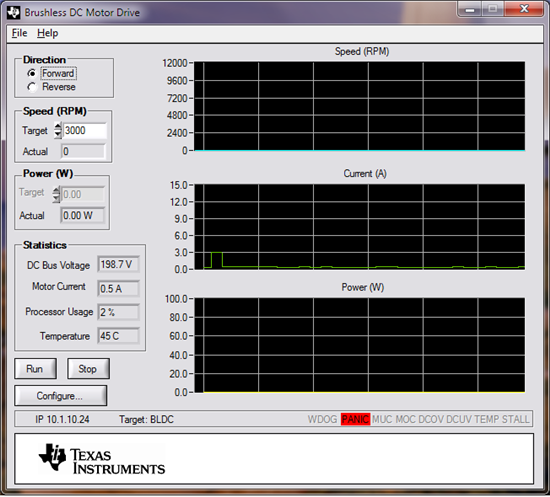
  • Thanks fellows it now works both ways (ROM_, NULL). Have to wonder if recently fixing Exosite IOT DNS hang up issue had some back ground conflict with LWIP timers. Looks like the ADC vector now works but dang that voltage sure look high! 

     http://e2e.ti.com/support/microcontrollers/tiva_arm/f/908/p/339176/1188908.aspx#1188908

  • BP101 said:
    dang that voltage sure looks HIGH! 

    Should your V_Bus approach 200V (as shown) that (slight) red frame about "Panic" may be understatement.  (is there not a (more suitable), "Run like He**!" icon?)

    Suggest that you add yet another layer of (protective, 1/4" polycarb surround) between all living things and your Controller/Motor... 

    You may also wish to:

    more tightly shut your eyes upon each/every "power-up"

    herd all women/children to blighted, nearby yards - (aka "burial ground") for Mr. Brett's abused/still smoldering components...

    renew your term-insurance as well as contract w/local house of worship...

    Perhaps the GUI would benefit from added curves showing both acceleration & distance traversed by over-voltaged components - quickly/forcefully/sub-orbitally departing your lab... (aka - BP's basement chamber of horrors)

  • Way to funny, though not a true value merely result of a shared 1.13 Vref feeding ANIx inputs. The Panic alert was leftover code being called to trigger from inside ADC0IntTrap() even when the PWM had or had not not been initialized.

    Triggering of ADCIntTrapHandler() for the timer called trigger processor ADC0-SS2 BusVoltage was supposed to only vector the interrupt into ADC0IntTrapIdle(), the idle mode voltage & now older temperature monitor function. However it was branching executing code in both ADC0 functions during idle mode. Might explain the return !MainIsRunnig() half way down the trap.

    The vector alias switch used to handle other methods of modulation has a side effect to probe where it was not invited. A quick rewrite of the idle interrupt handler now checks if MainIsRunning() return. No need to double up BusVoltage samples when temperature monitor (ADC0TriggerProcessor) event is handled separately left inside ADC0IntrapIdle() to be sampled only during idle mode. That temperature reading has been deprecated from ADC0IntTrap() once and for all.

  • BP101 said:
    not a true value merely result of a shared 1.13 Vref feeding ANIx inputs.

    Whew - that's certainly good to know...

    In light of that report - see no need (at present) for "distance traversed" graph!   Acceleration graph alone - of such,  "over-stressed" components" - (as they unceremoniously depart your chamber) should suffice...

  • Not sure what exactly happened in the vector handler traversing ADC0IntTrap() during idle. Do suspect the (g_pfnADC0Handler) switch is not working as intended or has some how become an dysfunctional ability during migration.  Adding a screen trace on sample 2 of sequencer 0 FIFO 0 prints an interesting picture. Do not suspect the ADC0 trigger processor is causing this behavior. Real time events tracing gets my vote!