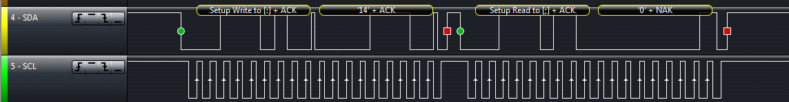
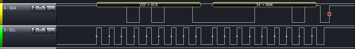
Hi there, I'm currently trying to work with i2c on my tm4c123gxl. as of now, i'm trying to receive the WHO_AM_I message from a MMA8452Q accelerometer. I'm modified the loop example, but i still end up receiving an echo of what i sent. any idea what went wrong? i am also declare that i'm quite new to i2c. thanks in advance.
http://www.freescale.com/files/sensors/doc/data_sheet/MMA8452Q.pdf
#include <stdbool.h>
#include <stdint.h>
#include "inc/hw_i2c.h"
#include "inc/hw_memmap.h"
#include "inc/hw_types.h"
#include "driverlib/gpio.h"
#include "driverlib/i2c.h"
#include "driverlib/pin_map.h"
#include "driverlib/sysctl.h"
#include "driverlib/uart.h"
#include "utils/uartstdio.h"
//
//*****************************************************************************

//*****************************************************************************
//
// Number of I2C data packets to send.
//
//*****************************************************************************
#define NUM_I2C_DATA 1

//
//*****************************************************************************
#define SLAVE_ADDRESS 0x1C

//*****************************************************************************
//
// This function sets up UART0 to be used for a console to display information
// as the example is running.
//
//*****************************************************************************
void
InitConsole(void)
{
	//
	// Enable GPIO port A which is used for UART0 pins.
	// TODO: change this to whichever GPIO port you are using.
	//
	SysCtlPeripheralEnable(SYSCTL_PERIPH_GPIOA);

	//
	// Configure the pin muxing for UART0 functions on port A0 and A1.
	// This step is not necessary if your part does not support pin muxing.
	// TODO: change this to select the port/pin you are using.
	//
	GPIOPinConfigure(GPIO_PA0_U0RX);
	GPIOPinConfigure(GPIO_PA1_U0TX);

	//
	// Enable UART0 so that we can configure the clock.
	//
	SysCtlPeripheralEnable(SYSCTL_PERIPH_UART0);

	//
	// Use the internal 16MHz oscillator as the UART clock source.
	//
	UARTClockSourceSet(UART0_BASE, UART_CLOCK_PIOSC);

	//
	// Select the alternate (UART) function for these pins.
	// TODO: change this to select the port/pin you are using.
	//
	GPIOPinTypeUART(GPIO_PORTA_BASE, GPIO_PIN_0 | GPIO_PIN_1);

	//
	// Initialize the UART for console I/O.
	//
	UARTStdioConfig(0, 38400, 16000000);
}

//*****************************************************************************
//
// Configure the I2C0 master and slave and connect them using loopback mode.
//
//*****************************************************************************
int
main(void)
{
	uint32_t pui32DataTx = 0;
	uint32_t pui32DataRx = 0;
	uint32_t ui32Index;

	//
	// Set the clocking to run directly from the external crystal/oscillator.
	// TODO: The SYSCTL_XTAL_ value must be changed to match the value of the
	// crystal on your board.
	//
	SysCtlClockSet(SYSCTL_SYSDIV_1 | SYSCTL_USE_OSC | SYSCTL_OSC_MAIN |
			SYSCTL_XTAL_16MHZ);

	//
	// The I2C0 peripheral must be enabled before use.
	//
	SysCtlPeripheralEnable(SYSCTL_PERIPH_I2C1);

	SysCtlPeripheralEnable(SYSCTL_PERIPH_GPIOA);

	GPIOPinConfigure(GPIO_PA6_I2C1SCL);
	GPIOPinConfigure(GPIO_PA7_I2C1SDA);
	GPIOPinTypeI2CSCL(GPIO_PORTA_BASE, GPIO_PIN_6);
	GPIOPinTypeI2C(GPIO_PORTA_BASE, GPIO_PIN_7);

	I2CMasterInitExpClk(I2C1_BASE, SysCtlClockGet(), false);

	I2CSlaveEnable(I2C1_BASE);

	I2CSlaveInit(I2C1_BASE, SLAVE_ADDRESS);

	I2CMasterSlaveAddrSet(I2C1_BASE, SLAVE_ADDRESS, false);

	InitConsole();

	UARTprintf("I2C Example\n");

	//
	// Indicate the direction of the data.
	//
	UARTprintf("Tranferring from: Master -> Slave\n");

	//
	// Display the data that the I2C1 master is transferring.
	//
	UARTprintf("  Sending: '0x0E'  . . .  ");

	//
	// Place the data to be sent in the data register
	//
	I2CMasterDataPut(I2C1_BASE, 0x0E);

	//
	// Initiate send of data from the master.  Since the loopback
	// mode is enabled, the master and slave units are connected
	// allowing us to receive the same data that we sent out.
	//
	I2CMasterControl(I2C1_BASE, I2C_MASTER_CMD_SINGLE_SEND);

	//
	// Wait until the slave has received and acknowledged the data.
	//
	while(!(I2CSlaveStatus(I2C1_BASE) & I2C_SLAVE_ACT_RREQ))
	{
	}

	//
	// Read the data from the slave.
	//
	pui32DataRx = I2CSlaveDataGet(I2C1_BASE);

	//
	// Wait until master module is done transferring.
	//
	while(I2CMasterBusy(I2C1_BASE))
	{
	}

	//
	// Display the data that the slave has received.
	//
	UARTprintf("Received: '0x%02x'\n", pui32DataRx);

	//
	// Reset receive buffer.
	//
	pui32DataRx = 0;

	//
	// Indicate the direction of the data.
	//
	UARTprintf("\n\nTranferring from: Slave -> Master\n");

	//
	// Modifiy the data direction to true, so that seeing the address will
	// indicate that the I2C Master is initiating a read from the slave.
	//
	I2CMasterSlaveAddrSet(I2C1_BASE, SLAVE_ADDRESS, true);

	//
	// Do a dummy receive to make sure you don't get junk on the first receive.
	//
	I2CMasterControl(I2C1_BASE, I2C_MASTER_CMD_SINGLE_RECEIVE);

	//
	// Dummy acknowledge and wait for the receive request from the master.
	// This is done to clear any flags that should not be set.
	//
	while(!(I2CSlaveStatus(I2C1_BASE) & I2C_SLAVE_ACT_TREQ))
	{
	}

	UARTprintf("  Sending: '0x0E'  . . .  ");

	//
	// Place the data to be sent in the data register
	//
	I2CSlaveDataPut(I2C1_BASE, 0x0E);

	//
	// Tell the master to read data.
	//
	I2CMasterControl(I2C1_BASE, I2C_MASTER_CMD_SINGLE_RECEIVE);

	//
	// Wait until the slave is done sending data.
	//
	while(!(I2CSlaveStatus(I2C1_BASE) & I2C_SLAVE_ACT_TREQ))
	{
	}

	//
	// Read the data from the master.
	//
	pui32DataRx = I2CMasterDataGet(I2C1_BASE);

	//
	// Display the data that the slave has received.
	//
	UARTprintf("Received: '0x%02x'\n", pui32DataRx);

	//
	// Tell the user that the test is done.
	//
	UARTprintf("\nDone.\n\n");

	//
	// Return no errors
	//
	return(0);
}