This thread has been locked.

If you have a related question, please click the "Ask a related question" button in the top right corner. The newly created question will be automatically linked to this question.

Connecting PCF8591 to TM4C1294XL via I2C

Other Parts Discussed in Thread: TM4C1294NCPDT

Hi, I've recently bought Tiva C TM4C1294XL board and I'm playing with it. Previously, I've worked with 8051 microcontroller and used PCF8591 DAC/ADC peripheral with it. Now I’d like to use it with Tiva and I ran into some problems. I’ve been googling for the past two weeks and couldn’t find any solution, so I’m hoping someone here has some experience with it, or can help.

Problem is that my PCF8591 acts like it’s not even connected to I2C bus, I can’t find it while scanning the bus, nor can I communicate with it.

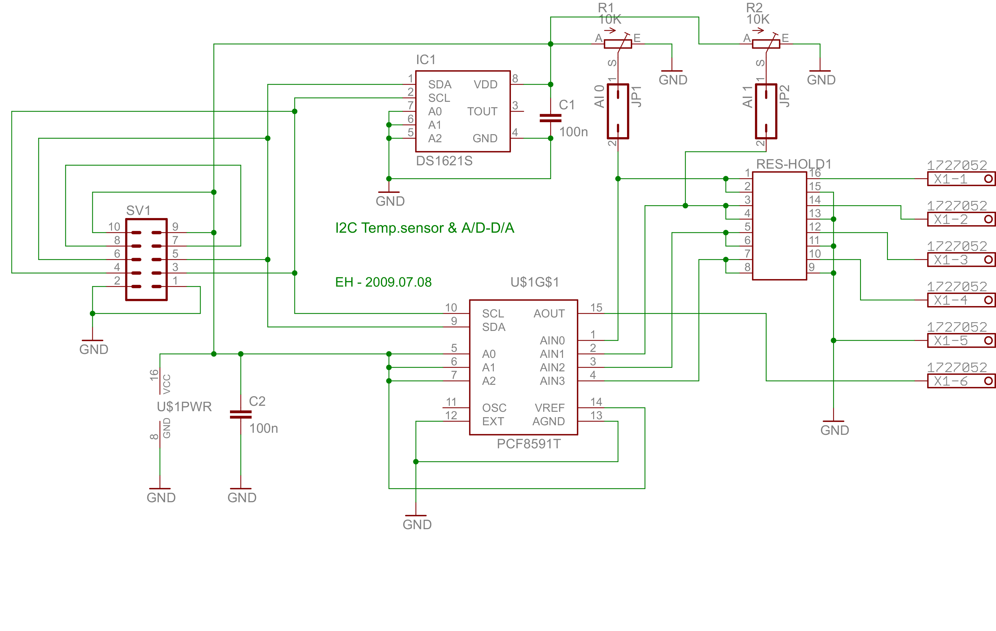
On the other hand, if you look at the code, you’ll see that I’m also using DS1631 temperature sensor, connected to the same I2C0 bus with address 0x90, and it works perfect, I’m able to communicate with it and get temperature readings. It is also the only device I see when performing I2C Bus scan.

PCF8591 datasheet - http://www.nxp.com/documents/data_sheet/PCF8591.pdf


#include <stdbool.h>
#include <stdint.h>
#include "inc/hw_i2c.h"
#include "inc/hw_ints.h"
#include "inc/hw_memmap.h"
#include "inc/hw_types.h"
#include "driverlib/gpio.h"
#include "driverlib/i2c.h"
#include "driverlib/interrupt.h"
#include "driverlib/pin_map.h"
#include "driverlib/sysctl.h"
#include "driverlib/uart.h"
#include "utils/uartstdio.h"
#include "driverlib/rom_map.h"
#include "inc/hw_types.h"
#include "inc/hw_gpio.h"

uint32_t ui32SysClock;
volatile uint8_t data[10];

const uint8_t DS1631address = 0x90;
const uint8_t DACaddress = 0x9E;
const bool DebuggingMode = true;


void InitConsole(void)
{
    SysCtlPeripheralEnable(SYSCTL_PERIPH_GPIOA);
    GPIOPinConfigure(GPIO_PA0_U0RX);
    GPIOPinConfigure(GPIO_PA1_U0TX);
    SysCtlPeripheralEnable(SYSCTL_PERIPH_UART0);
    UARTClockSourceSet(UART0_BASE, UART_CLOCK_PIOSC);
    GPIOPinTypeUART(GPIO_PORTA_BASE, GPIO_PIN_0 | GPIO_PIN_1);
    UARTStdioConfig(0, 115200, 16000000);
}

void ftoa(float f,char *buf)
{
       /*Function acquired from forum:
        * http://e2e.ti.com/support/microcontrollers/stellaris_arm/f/471/p/44193/156824.aspx
        */
    int pos=0,ix,dp,num;
    if (f<0)
    {
        buf[pos++]='-';
        f = -f;
    }
    dp=0;
    while (f>=10.0)
    {
        f=f/10.0;
        dp++;
    }
    for (ix=1;ix<8;ix++)
    {
            num = (int)f;
            f=f-num;
            if (num>9)
                buf[pos++]='#';
            else
                buf[pos++]='0'+num;
            if (dp==0) buf[pos++]='.';
            f=f*10.0;
            dp--;
    }
}


void i2c0_init()
{
       MAP_SysCtlPeripheralEnable(SYSCTL_PERIPH_I2C0);
       MAP_SysCtlPeripheralEnable(SYSCTL_PERIPH_GPIOB);

       MAP_GPIOPinTypeI2C(GPIO_PORTB_BASE, GPIO_PIN_3);
       MAP_GPIOPinConfigure(GPIO_PB3_I2C0SDA);

       MAP_GPIOPinTypeI2CSCL(GPIO_PORTB_BASE, GPIO_PIN_2);
       MAP_GPIOPinConfigure(GPIO_PB2_I2C0SCL);

       I2CMasterInitExpClk(I2C0_BASE, SysCtlClockGet(), false);
              while (I2CMasterBusy(I2C0_BASE));
       if (DebuggingMode) UARTprintf("\n Initializing I2C0 -> Error: %u ",I2CMasterErr(I2C0_BASE));

}

uint32_t i2c0_write(uint8_t addr, uint8_t value)
{
    uint32_t error = { 0 };

    I2CMasterSlaveAddrSet(I2C0_BASE, addr>>1, false);
       while (I2CMasterBusy(I2C0_BASE));
    I2CMasterDataPut(I2C0_BASE, value);
       while (I2CMasterBusy(I2C0_BASE));
    I2CMasterControl(I2C0_BASE, I2C_MASTER_CMD_SINGLE_SEND);
       while (I2CMasterBusy(I2C0_BASE));
    if (DebuggingMode) UARTprintf("\n Sending data(%X) -> Error: %u ",value, I2CMasterErr(I2C0_BASE));
    
    return I2CMasterErr(I2C0_BASE);
}

void i2c0_read(uint8_t addr, uint8_t *RxData, uint8_t N)
{
       uint8_t i;

       I2CMasterSlaveAddrSet(I2C0_BASE, addr>>1, true);
              while (I2CMasterBusy(I2C0_BASE));

       if (N==1)
       {
              I2CMasterControl(I2C0_BASE, I2C_MASTER_CMD_SINGLE_RECEIVE);
                     while (I2CMasterBusy(I2C0_BASE));
              RxData[0]=I2CMasterDataGet(I2C0_BASE);
                     while (I2CMasterBusy(I2C0_BASE));
              if (DebuggingMode) UARTprintf("\n Reading data(%X) -> Error: %u ",RxData[0], I2CMasterErr(I2C0_BASE));
       }
       else
       {
              I2CMasterControl(I2C0_BASE, I2C_MASTER_CMD_BURST_RECEIVE_START);
                     while (I2CMasterBusy(I2C0_BASE));
              RxData[0]=I2CMasterDataGet(I2C0_BASE);
                     while (I2CMasterBusy(I2C0_BASE));
              if (DebuggingMode) UARTprintf("\n Reading data(%X) -> Error: %u ",RxData[0], I2CMasterErr(I2C0_BASE));

              for (i=1;i<(N-1);i++)
              {
                     I2CMasterControl(I2C0_BASE, I2C_MASTER_CMD_BURST_RECEIVE_CONT);
                           while (I2CMasterBusy(I2C0_BASE));
                     RxData[i]=I2CMasterDataGet(I2C0_BASE);
                           while (I2CMasterBusy(I2C0_BASE));
                     if (DebuggingMode) UARTprintf("\n Reading data(%X) -> Error: %u ",RxData[i], I2CMasterErr(I2C0_BASE));
              }

              I2CMasterControl(I2C0_BASE, I2C_MASTER_CMD_BURST_RECEIVE_FINISH);
                     while (I2CMasterBusy(I2C0_BASE));
              RxData[N-1]=I2CMasterDataGet(I2C0_BASE);
                     while (I2CMasterBusy(I2C0_BASE));
              if (DebuggingMode) UARTprintf("\n Reading data(%X) -> Error: %u ",RxData[N-1], I2CMasterErr(I2C0_BASE));
       }
}

void DS1631_init()
{
       i2c0_write(DS1631address,DS1631address);
       i2c0_write(DS1631address,0xAC);
       i2c0_write(DS1631address,0x0C);

       i2c0_write(DS1631address,DS1631address);
       i2c0_write(DS1631address,0x51);
}

float get_temperature()
{
       uint8_t Rx[2];
       float temperature;

       i2c0_write(DS1631address,DS1631address);
       i2c0_write(DS1631address,0xAA);

       i2c0_read(DS1631address,Rx,2);

       temperature=Rx[0]+((Rx[1]&0x80) ? 0.5:0);
       return temperature;
}

uint8_t read_ain(uint8_t channel)
{
       uint8_t Rx[2];
       if (channel > 3) channel=3;
       i2c0_write(DACaddress,DACaddress);
       i2c0_write(DACaddress,0x40+channel);
       i2c0_read(DACaddress,Rx,2);
       return Rx[1];
}

void set_dac(uint8_t value)
{
       i2c0_write(DACaddress,DACaddress);
       i2c0_write(DACaddress,0x40);
       i2c0_write(DACaddress,value);
}

int
main(void)
{      
       ui32SysClock = MAP_SysCtlClockFreqSet((SYSCTL_XTAL_25MHZ |
                SYSCTL_OSC_MAIN | SYSCTL_USE_PLL |
                SYSCTL_CFG_VCO_480), 120000000);

              MAP_SysCtlPeripheralEnable(SYSCTL_PERIPH_GPION);
              MAP_GPIOPinTypeGPIOOutput(GPIO_PORTN_BASE,GPIO_PIN_0 | GPIO_PIN_1);

              GPIOPinWrite(GPIO_PORTN_BASE,GPIO_PIN_0,0);
              GPIOPinWrite(GPIO_PORTN_BASE,GPIO_PIN_1,0);
 
              InitConsole();
              i2c0_init();
              DS1631_init();

              uint8_t ain=read_ain(0);

              char myTemp[6];
              ftoa(get_temperature(),myTemp);

              UARTprintf("\n Got temperature: %s ",myTemp);
              UARTprintf("\n Reading channel 1: %u",ain);

              set_dac(150);


        GPIOPinWrite(GPIO_PORTN_BASE,GPIO_PIN_1,0xFF);
        UARTprintf("\n  Done!...\n");
        while(1);

}

Lastly, this is a working part of code from 8051 with which DAC/ADC module works fine:

#define PCF8591_adr 0x9E

int read_ain(unsigned char channel)
{
int ad_byte;

       if(channel > 3) channel = 3;
       i2c_start();                         
       i2c_write(PCF8591_adr);   
       i2c_write(0x40+channel);
       i2c_start();
       i2c_write(PCF8591_adr+1);
       ad_byte = i2c_read(ACK);
       ad_byte = i2c_read(NACK);
       i2c_stop();
       return ad_byte;
}

void set_dac(unsigned char value)
{              
i2c_start();             
i2c_write(PCF8591_adr);
i2c_write(0x40);
i2c_write(value);
i2c_stop(); }


Thanks for your time.

  • I think I see something you may want to dig into to make sure you understand how the tiva i2c module works.

    I can read the 8051 code at a glance. The tiva code will necessarily be more complicated just due to how the tiva i2c module works. So when you do i2c_start(); i2c_write(PCF8591_adr); i2c_write(0x40); on the 8051, the start condition is only sent to the i2c bus once by the 8051.

    When you do i2c0_write(DACaddress, DACaddress); i2c0_write(DACaddress, 0x40); on the tiva it sends commands to the tiva state machine and this is what I would expect it to produce on the bus: (wrong thing to do on the bus, but it will do this)

    1. START
    2. DACaddress (master sends address and commands a write)
    3. DACaddress (interpreted as a data byte by the DAC, probably not what you meant)
    4. STOP (then the first i2c0_write() call returns)
    5. START (start the second i2c0_write() call)
    6. DACaddress (master sends address and commands a write)
    7. 0x40 (data byte for the DAC)
    8. STOP (probably not what you meant, second i2c0_write() call returns)
    9. START (start the third i2c0_write() call)
    10. ...

    Please take a look at the CPU datasheet for the TM4C1294NCPDT on your board and see how the tiva i2c module has a state machine which tries to automatically do things like START and STOP for you.

    Cheers,

    David

  • Hello David,

    The i2c0_write seems a little strange to me. It should be more like

        I2CMasterSlaveAddrSet(I2C0_BASE, addr>>1, false);
        I2CMasterDataPut(I2C0_BASE, value);
        I2CMasterControl(I2C0_BASE, I2C_MASTER_CMD_SINGLE_SEND);
        while (I2CMasterBusy(I2C0_BASE));

    Also it would be useful if you can send the LA/Scope plot of what you see on the I2C Bus with the original code.

    Regards

    Amit

  • Hi Amit,

    You write, "Hello David" but I think you meant "Hello Vedran" ?

    David

  • Hi David and Amit!

    I tried changing my i2c0_write function so that it looks like:

    uint32_t i2c0_write(uint8_t addr, uint8_t *Tx, uint8_t N)
    {
    	uint8_t i;
    	I2CMasterSlaveAddrSet(I2C0_BASE, addr>>1, false);
    	if(N==1)
    	{
    		I2CMasterDataPut(I2C0_BASE, Tx[0]);
    			//while (I2CMasterBusy(I2C0_BASE));
    		I2CMasterControl(I2C0_BASE, I2C_MASTER_CMD_SINGLE_SEND);
    			while (I2CMasterBusy(I2C0_BASE));
    		if (DebuggingMode) UARTprintf("\n Sending data(%X) -> Error: %u ",Tx[0], I2CMasterErr(I2C0_BASE));
    	}
    	else
    	{
    		I2CMasterDataPut(I2C0_BASE, Tx[0]);
    			//while (I2CMasterBusy(I2C0_BASE));
    		I2CMasterControl(I2C0_BASE, I2C_MASTER_CMD_BURST_SEND_START);
    			while (I2CMasterBusy(I2C0_BASE));
    		if (DebuggingMode) UARTprintf("\n Sending data(%X) -> Error: %u ",Tx[0], I2CMasterErr(I2C0_BASE));
    		for (i=1;i<(N-1);i++)
    		{
    			I2CMasterDataPut(I2C0_BASE, Tx[i]);
    				//while (I2CMasterBusy(I2C0_BASE));
    			I2CMasterControl(I2C0_BASE, I2C_MASTER_CMD_BURST_SEND_CONT);
    				while (I2CMasterBusy(I2C0_BASE));
    			if (DebuggingMode) UARTprintf("\n Reading data(%X) -> Error: %u ",Tx[i], I2CMasterErr(I2C0_BASE));
    		};
    		I2CMasterDataPut(I2C0_BASE, Tx[N-1]);
    			//while (I2CMasterBusy(I2C0_BASE));
    		I2CMasterControl(I2C0_BASE, I2C_MASTER_CMD_BURST_SEND_STOP);
    			while (I2CMasterBusy(I2C0_BASE));
    		if (DebuggingMode) UARTprintf("\n Sending data(%X) -> Error: %u ",Tx[N-1], I2CMasterErr(I2C0_BASE));
    	}
        return I2CMasterErr(I2C0_BASE);
    }

    And other functions as well:

    uint8_t read_ain(uint8_t channel)
    {
    	uint8_t Rx[3];
    
    	if (channel > 3) channel=3;
    	uint8_t Tx[]={0x40+channel};
    
    	i2c0_write(DACaddress,Tx,1);
    	i2c0_read(DACaddress,Rx,3);
    
    	return Rx[0];
    }
    void set_dac(uint8_t value)
    {
    	uint8_t Tx[]={0x40,0xFF};
    	i2c0_write(DACaddress,Tx,2);
    
    }

    Temperature sensor still works fine but there's no response whatsoever from DAC. I've also comented-out while loop as Amit suggested, even though I don't think they could cause any problem, they are there just to make sure that before any operation I2C is free. And unfortunately I can't provide you with any plots because I don't have a device for that at my disposal.

  • Hello Vedran

    Do you have a schematic of how the DAC is connected to the TM4C?

    Because if the Temp Sensor is working and not DAC, then there is something on the DAC connections we need to check.

    Regards

    Amit

  • Both ADC and temperature sensor are soldered onto the same PCB which I got from university, and as I stated before, they work when connected to old 8051 microcontroller so the board is not the problem. Right now I'm using 4k7 pull-up resistors, I'll try few different pull-up resistors today, maybe that's the problem.

    And yes, when connecting to Tiva, I connect both pins 1&2 to GND, 3&4 to SCL etc.

  • Hello Vedran

    In the schematic below, the VDD and VSS to PC8591T is not shown.?

    Regards

    Amit

  • Hi Amit, note on the left of PCF8591 there is U$1PWR mark with pins 8(VSS) connected to ground and 16(VDD) as VCC.

    I've just tried connecting 10k pull-up resistors and switching the above PCB on external power supply while connecting grounds, still nothing(temperature sensor still works fine), so I think it's software problem. Something with start/stop conditions.

  • Hello Vedran

    At this point I would ask you to get a scope or LA plot because by data sheet it seems to be the correct operation.

    Also

    Regards

  • After connecting SDA and SCL lines to oscilloscope I've realized that SDA line is stuck low(at 410mV) while SCL is at 3.2V (both having 10k pull-ups). At the same time temperature sensor gives accurate readings. Even when I disconnect everything from SDA and SCL lines(except for pull-ups), leaving only probes - SDA still stays at 410mV.

    When pull-ups removed both lines fall between 20-50mV.

    EDIT: I found this http://processors.wiki.ti.com/index.php/I2C_Tips but as far as I've understood this article, slave is the problem, holding the line low, when slave is removed, there shouldn't be any problems. Or I misunderstood the article?

  • Hello Vedran,

    With pull-ups removed it is natural that two SCL and SDA will fall to a low voltage as it is OPEN DRAIN and that there is no active high driver.

    What is strange is that with the pull up connected but the two Slave device removed or connected the SDA is low, which would not allow any of the Slaves to work. It is evident that there is a weak driver from one of the Slaves.

    I would suggest two experiments to do in the following order and let me know what you observer

    1. Change the IO Init Sequence to:

           MAP_GPIOPinConfigure(GPIO_PB3_I2C0SDA);
           MAP_GPIOPinConfigure(GPIO_PB2_I2C0SCL);
           MAP_GPIOPinTypeI2CSCL(GPIO_PORTB_BASE, GPIO_PIN_2);
           MAP_GPIOPinTypeI2C(GPIO_PORTB_BASE, GPIO_PIN_3);

    2. Change the System Clock to 16MHz PIOSC instead of 120MHz PLL.

    3.Remove the Temp Sensor and capture the first I2C communication for DAC/ADC and send it across.

    Regards

    Amit

  • Changing the clock to 16MHz with following settings:

    MAP_SysCtlClockFreqSet((SYSCTL_XTAL_25MHZ | SYSCTL_OSC_MAIN |
         	SYSCTL_USE_PLL |
         	SYSCTL_CFG_VCO_320), 16000000);

    Solves my problem, finally getting response from ADC.

    Thank you Amit, and David for your help!

  • Hello Vedran,

    I believe the timing requirement for the ADC/DAC IC is 4.7us minimum to detect a START condition, which cannot be met with I2C Controller of TIVA at 120MHz. That is why I suggested to move the System Clock to 16MHz.

    Regards

    Amit