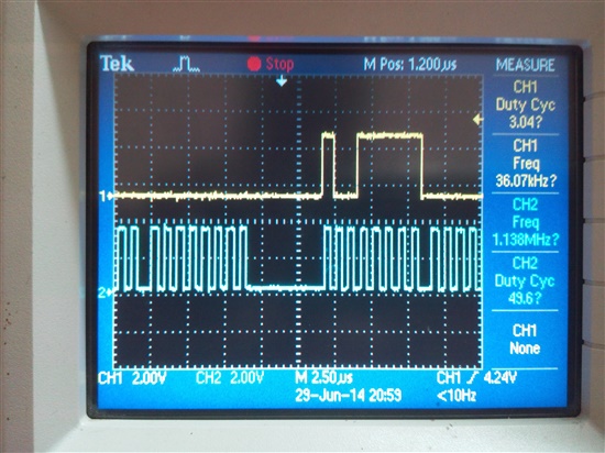
HI,
I am trying to access the Serial flash using tm4c1231h6pm.
SSI0 -> SST25VF016B ( supports mode 0 and mode 3)
SSI0CLK(PA2) - clk
-SSI0Fss(PA3) - CS
-SSI0Rx(PA4) - Tx
-SSI0Tx(PA5) - Rx
typedef unsigned char uint8; // defined for unsigned 8-bits integer variable
typedef signed char int8; // defined for signed 8-bits integer variable
typedef unsigned short uint16; // defined for unsigned 16-bits integer variable
typedef signed short int16; // defined for signed 16-bits integer variable
typedef unsigned long uint32; // defined for unsigned 32-bits integer variable
typedef signed long int32; // defined for signed 32-bits integer variable
void spi configuration()
{
//
// The SSI0 peripheral must be enabled for use.
//
SysCtlPeripheralEnable(SYSCTL_PERIPH_SSI0);
//
// For this example SSI0 is used with PortA[5:2]. GPIO port A needs to be
// enabled so these pins can be used.
//
SysCtlPeripheralEnable(SYSCTL_PERIPH_GPIOA);
//
// Configure the pin muxing for SSI0 functions on port A2, A3, A4, and A5.
// This step is not necessary if your part does not support pin muxing.
//
GPIOPinConfigure(GPIO_PA2_SSI0CLK);
GPIOPinConfigure(GPIO_PA3_SSI0FSS);
GPIOPinConfigure(GPIO_PA4_SSI0RX);
GPIOPinConfigure(GPIO_PA5_SSI0TX);
//
// Configure the GPIO settings for the SSI pins. This function also gives
// control of these pins to the SSI hardware. Consult the data sheet to
// see which functions are allocated per pin.
// The pins are assigned as follows:
// PA5 - SSI0Tx
// PA4 - SSI0Rx
// PA3 - SSI0Fss
// PA2 - SSI0CLK
//
GPIOPinTypeSSI(GPIO_PORTA_BASE, GPIO_PIN_5 | GPIO_PIN_4 | GPIO_PIN_3 |
GPIO_PIN_2);
//
// Configure and enable the SSI0 port for SPI master mode.
//
SSIConfigSetExpClk(SSI0_BASE, SysCtlClockGet(), SSI_FRF_MOTO_MODE_0,
SSI_MODE_MASTER, 20000000, 8);
//
// Enable the SSI0 module.
//
SSIEnable(SSI0_BASE);
}
void Send_Byte(uint8 data)
{
uint32 NullData;
SSIDataPut(SSI0_BASE, data);
SSIDataGet(SSI0_BASE, &NullData); // dummy read ( is required ??)
}
uint8 Get_Byte(void)
{
uint32 ReadData;
SSIDataPut(SSI0_BASE, 0xFF); // dummy write ( is required to read ??)
SSIDataGet(SSI0_BASE, &ReadData);
return (uint8)ReadData;
}
uint8 RdID(uint32* RcvbufPt)
{
uint32 temp = 0;
GPIOPinWrite(GPIO_PORTA_BASE,GPIO_PIN_3,0) ; //Chip select low
Send_Byte(0x9F); // command to send to get the id
temp = (temp | Get_Byte()) << 8;
temp = (temp | Get_Byte()) << 8;
temp = (temp | Get_Byte()); // 0xBF2541
GPIOPinWrite(GPIO_PORTA_BASE,GPIO_PIN_3,1) ; //chip select high
*RcvbufPt = temp;
return 1;
}
uint32 ChipID = 0;
int main()
{
//80mhz
ROM_SysCtlClockSet(SYSCTL_SYSDIV_2_5 | SYSCTL_USE_PLL | SYSCTL_OSC_MAIN |
SYSCTL_XTAL_10MHZ);
spi_configuration();
RdID(&ChipID);
}
i cant able to read back the id, i want to know any issue in the code, how to debug where is the issue. plz guide on this.
SSI0 -> SST25VF016B ( supports mode 0 and mode3)


 SSI0CLK(PA2) -  clk
-SSI0Fss(PA3) -  CS
-SSI0Rx(PA4)  -  Tx
-SSI0Tx(PA5)  -   Rx


typedef unsigned char  uint8;                   // defined for unsigned 8-bits integer variable
typedef signed   char  int8;                    // defined for signed 8-bits integer variable
typedef unsigned short uint16;                  // defined for unsigned 16-bits integer variable
typedef signed   short int16;                   // defined for signed 16-bits integer variable
typedef unsigned long   uint32;                  // defined for unsigned 32-bits integer variable
typedef signed   long   int32;                   // defined for signed 32-bits integer variable

void spi configuration()

{


//
    // The SSI0 peripheral must be enabled for use.
    //
    SysCtlPeripheralEnable(SYSCTL_PERIPH_SSI0);

    //
    // For this example SSI0 is used with PortA[5:2].  GPIO port A needs to be
    // enabled so these pins can be used.
    //
    SysCtlPeripheralEnable(SYSCTL_PERIPH_GPIOA);

    //
    // Configure the pin muxing for SSI0 functions on port A2, A3, A4, and A5.
    // This step is not necessary if your part does not support pin muxing.
    //
    GPIOPinConfigure(GPIO_PA2_SSI0CLK);
    GPIOPinConfigure(GPIO_PA3_SSI0FSS);
    GPIOPinConfigure(GPIO_PA4_SSI0RX);
    GPIOPinConfigure(GPIO_PA5_SSI0TX);

    //
    // Configure the GPIO settings for the SSI pins.  This function also gives
    // control of these pins to the SSI hardware.  Consult the data sheet to
    // see which functions are allocated per pin.
    // The pins are assigned as follows:
    //      PA5 - SSI0Tx
    //      PA4 - SSI0Rx
    //      PA3 - SSI0Fss
    //      PA2 - SSI0CLK
    //
    GPIOPinTypeSSI(GPIO_PORTA_BASE, GPIO_PIN_5 | GPIO_PIN_4 | GPIO_PIN_3 |
                   GPIO_PIN_2);

    //
    // Configure and enable the SSI0 port for SPI master mode.
    //
    SSIConfigSetExpClk(SSI0_BASE, SysCtlClockGet(), SSI_FRF_MOTO_MODE_0,
                       SSI_MODE_MASTER, 20000000, 8);

    //
    // Enable the SSI0 module.
    //
    SSIEnable(SSI0_BASE);

}

 void Send_Byte(uint8 data)
    {
       uint32 NullData;
       SSIDataPut(SSI0_BASE, data);
       SSIDataGet(SSI0_BASE, &NullData);       // dummy read  ( is required ??)
    }

  uint8 Get_Byte(void)
    {
       uint32 ReadData;

       SSIDataPut(SSI0_BASE, 0xFF);        // dummy write ( is required to read ??)
       SSIDataGet(SSI0_BASE, &ReadData);
       return (uint8)ReadData;

    }

  uint8 RdID(uint32* RcvbufPt)
    {
        uint32 temp = 0;


            GPIOPinWrite(GPIO_PORTA_BASE,GPIO_PIN_3,0) ;    //Chip select low
            Send_Byte(0x9F);                // command to send to get the id

            temp = (temp | Get_Byte()) << 8;
            temp = (temp | Get_Byte()) << 8;
                    temp = (temp | Get_Byte());     // 0xBF2541
                    GPIOPinWrite(GPIO_PORTA_BASE,GPIO_PIN_3,1) ;    //chip select high
            *RcvbufPt = temp;
            return 1;


    }

uint32  ChipID = 0;
int main()
{
	//80mhz
	ROM_SysCtlClockSet(SYSCTL_SYSDIV_2_5 | SYSCTL_USE_PLL | SYSCTL_OSC_MAIN |
                       SYSCTL_XTAL_10MHZ);

	spi_configuration();

 	RdID(&ChipID);

}


