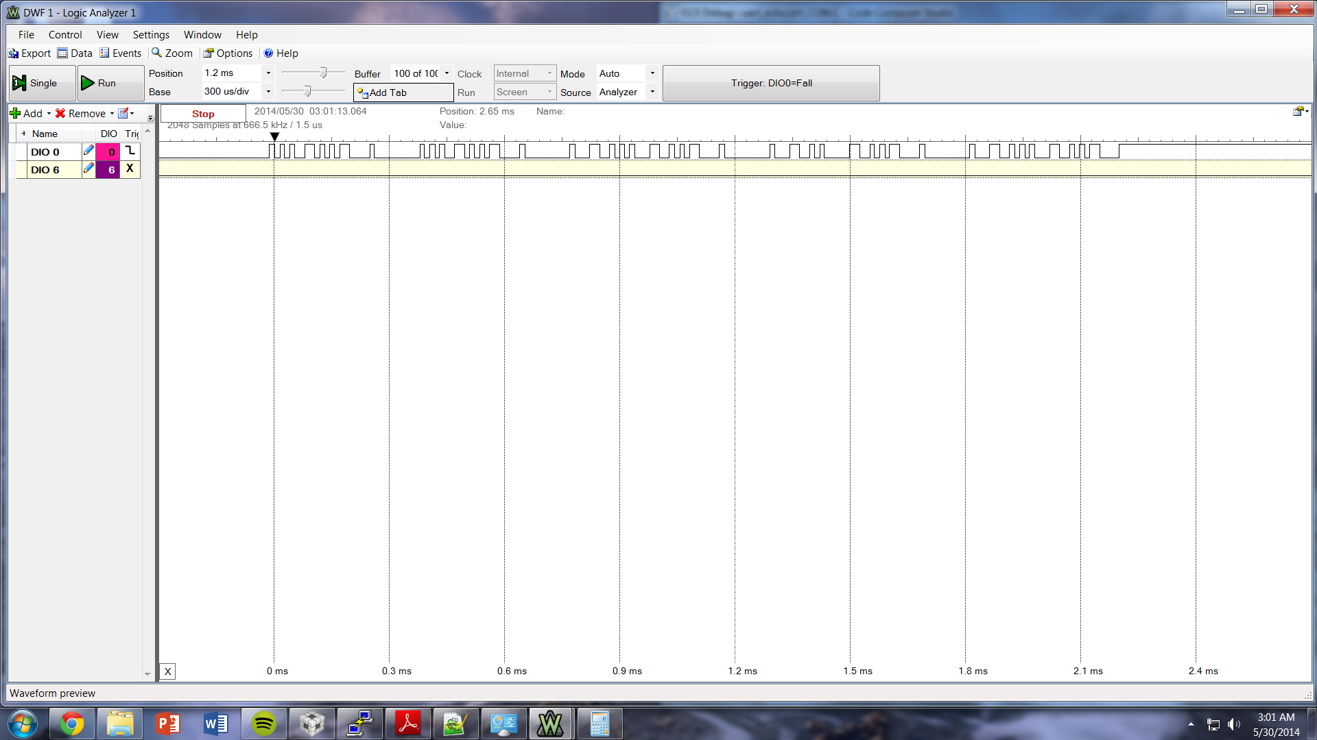
I am trying to communicate with a sensor via UART (UART1_BASE) while also communicating with a terminal (UART0_BASE). I have attached the communication portion of my program and it is currently set to only one UART at a time. When I select UART0 I have no problem transmitting all of the strings to the terminal, however I only get a set amount (with no delays I get 5 writes) when I use UART1 (Seen on oscilloscope). I change UART by switching commented portions of code and replace UARTX with correct number.
Please help!
/*
 * pH_Control.c
 *
 *  Created on: May 29, 2014
 *      Author: Jordan
 */

#include <stdio.h>
#include <math.h>
#include <string.h>
#include <stdlib.h>
#include <stdint.h>
#include <stdbool.h>
#include "inc/hw_ints.h"
#include "inc/hw_memmap.h"
#include "driverlib/debug.h"
#include "driverlib/fpu.h"
#include "driverlib/gpio.h"
#include "driverlib/interrupt.h"
#include "driverlib/pin_map.h"
#include "driverlib/rom.h"
#include "driverlib/sysctl.h"
#include "driverlib/uart.h"
#include "Setup.h" 	/*  Includes strings to be sent to stamp
					 *  Commands include: set_(4,7,10), reset,
					 *  info, led_(on,off)
					 */


// Commands:
void UART_write (uint32_t ui32Base);
void init_TM4C (void);

// Variables:
char pH_out[20];	// char array used to hold outgoing pH data


int main(void)
{
	//Initialize Microcontroller
	init_TM4C();

	//Initialize Port to write to sensor

	ROM_UARTCharPutNonBlocking(UART1_BASE, '5');


	while(1)
	{
		//
		// Blink the LED to show a character transfer is occurring.
		//
		GPIOPinWrite(GPIO_PORTF_BASE, GPIO_PIN_2, GPIO_PIN_2);

		//
		// Delay for 1 millisecond.  Each SysCtlDelay is about 3 clocks.
		//
		SysCtlDelay(SysCtlClockGet() / (1 * 3));

		//
		// Turn off the LED
		//
		GPIOPinWrite(GPIO_PORTF_BASE, GPIO_PIN_2, 0);
	}
}


void init_TM4C (void)
{
	//
    // Enable lazy stacking for interrupt handlers.  This allows floating-point
    // instructions to be used within interrupt handlers, but at the expense of
    // extra stack usage.
    //
    ROM_FPUEnable();
    ROM_FPULazyStackingEnable();

    //
    // Set the clocking to run directly from the crystal.
    //
    ROM_SysCtlClockSet(SYSCTL_SYSDIV_1 | SYSCTL_USE_OSC | SYSCTL_OSC_MAIN |
                       SYSCTL_XTAL_16MHZ);

    //
    // Enable the GPIO port that is used for the on-board LED.
    //
    ROM_SysCtlPeripheralEnable(SYSCTL_PERIPH_GPIOF);

    //
    // Enable the GPIO pins for the LED (PF2).
    //
    ROM_GPIOPinTypeGPIOOutput(GPIO_PORTF_BASE, GPIO_PIN_2);

    //
    // Enable the peripherals used by this example.
    //
    ROM_SysCtlPeripheralEnable(SYSCTL_PERIPH_UART1);
    ROM_SysCtlPeripheralEnable(SYSCTL_PERIPH_GPIOC);

    //
    // Enable processor interrupts.
    //
    ROM_IntMasterEnable();

    //
    // Set GPIO A0 and A1 as UART pins.
    //
    GPIOPinConfigure(GPIO_PC4_U1RX);
    GPIOPinConfigure(GPIO_PC5_U1TX);
    ROM_GPIOPinTypeUART(GPIO_PORTC_BASE, GPIO_PIN_4 | GPIO_PIN_5);

    //
    // Configure the UART for 115,200, 8-N-1 operation.
    //
    ROM_UARTConfigSetExpClk(UART1_BASE, ROM_SysCtlClockGet(), 115200,
                            (UART_CONFIG_WLEN_8 | UART_CONFIG_STOP_ONE |
                             UART_CONFIG_PAR_NONE));

    //
    // Enable the UART interrupt.
    //
    ROM_IntEnable(INT_UART1);
    ROM_UARTIntEnable(UART1_BASE, UART_INT_RX | UART_INT_RT);
}

// Write relevant string to given base
void UART_write (uint32_t ui32Base)
{
//	init_base1();
	b = sizeof(pH_out);
	for (a = 0; a < b; a++)
	{
		ROM_UARTCharPutNonBlocking(ui32Base, pH_out[a]);

		//
		// Blink the LED to show a character transfer is occuring.
		//
		GPIOPinWrite(GPIO_PORTF_BASE, GPIO_PIN_2, GPIO_PIN_2);

		//
		// Delay for 1 millisecond.  Each SysCtlDelay is about 3 clocks.
		//
		SysCtlDelay(SysCtlClockGet() / (1000 * 3));

		//
		// Turn off the LED
		//
		GPIOPinWrite(GPIO_PORTF_BASE, GPIO_PIN_2, 0);
	}
	SysCtlDelay(SysCtlClockGet() / (1));
}
/*
* Setup.h
*
* Created on: May 27, 2014
* Author: Jordan
*/

#ifndef SETUP_H_
#define SETUP_H_

//*********************************************************************************************//
// Internal Strings:
//*********************************************************************************************//


//*********************************************************************************************//
// Stamp Commands:
//*********************************************************************************************//

//Universal Commands:
char reset[20] = "X\r"; // Command to reset the device to factoy default mode (R)
char read_cont[20] = "c\r"; // Command to put stamp in continuous reading mode (C)
char cont_esc[20] = "e\r"; // Command to take stamp out of continuous mode (E)
char read_one[20] = "R\r"; // Command to put stamp in single-read mode (S)
char info[20] = "I\r"; // Command to query the information (Q)
char led_off[20] = "L0\r"; // Command to turn leds OFF (0)
char led_on[20] = "L1\r"; // Command to turn leds ON (L)

//pH Commands:
char set_4[20] = "f\r"; // Command to calibrate to a pH of 4.00 (1)
char set_7[20] = "s\r"; // Command to calibrate to a pH of 7.00 (2)
char set_10[20] = "t\r"; // Command to calibrate to a pH of 10.00 (3)


#endif /* SETUP_H_ */