This thread has been locked.

If you have a related question, please click the "Ask a related question" button in the top right corner. The newly created question will be automatically linked to this question.

QEI not working properly(TM4C123BH6PM)

Other Parts Discussed in Thread: TM4C123BH6PM

Hi, I'm using QEI in order to count a rotation of a remote car's wheel.

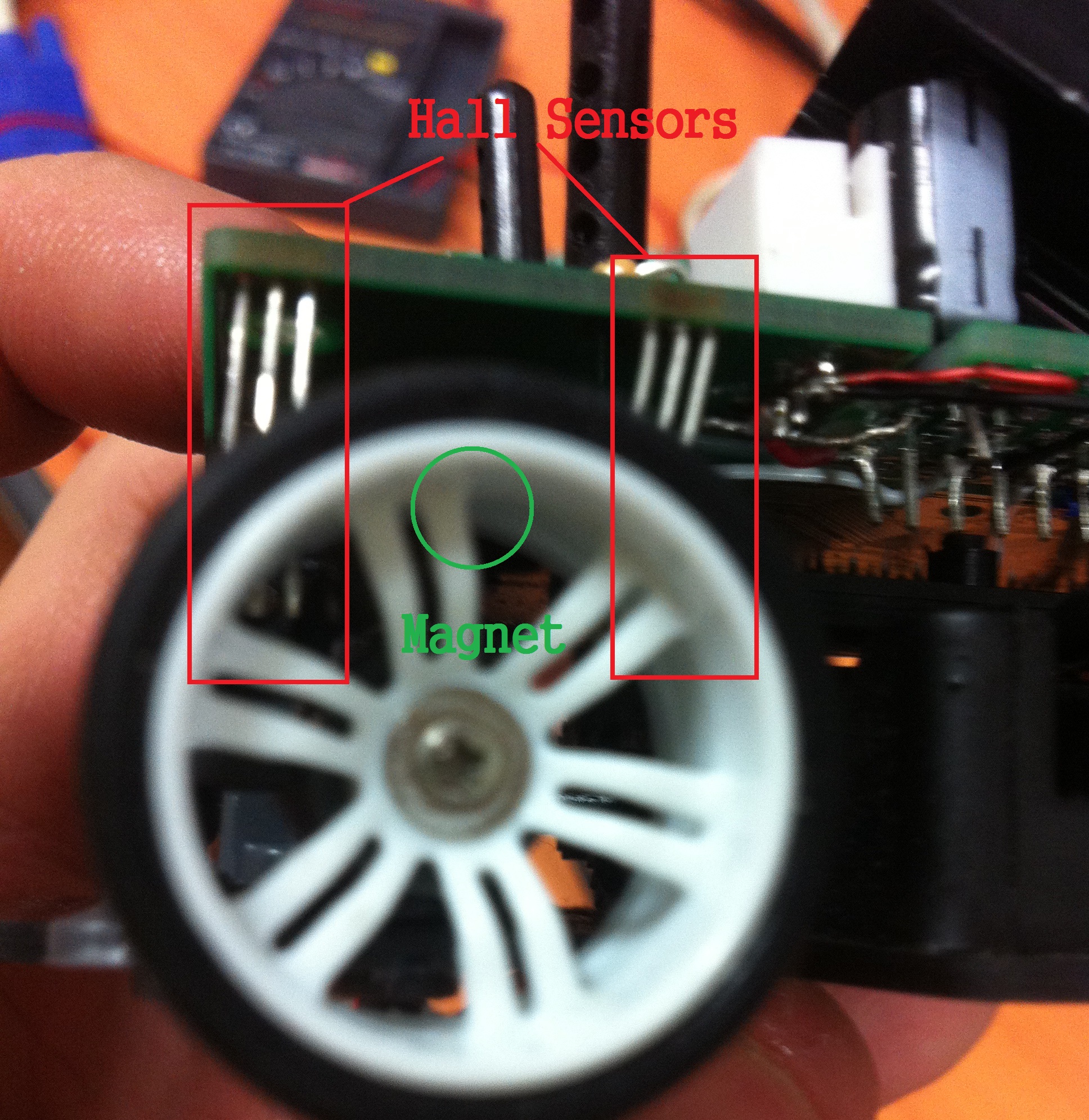
I connected a digital hall sensor output to QEI module 1's input A(PHA1/PC5, capture mode :  Only PhA).

The hall sensor is WSH131-XPAN3.

(Datasheet link : http://pdf1.alldatasheet.co.kr/datasheet-pdf/view/227165/WINSON/WSH131-XPAN3.html  )

Attaching a magnet to the wheel, the pulse comes out well.

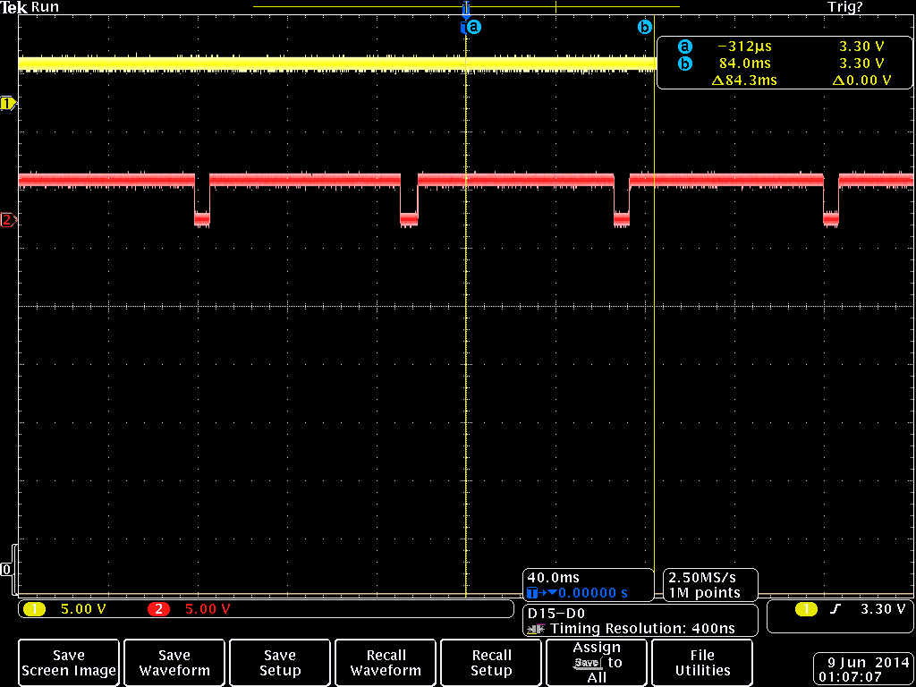
The yellow pulse is the IDX1. It is constantly digital '1'.

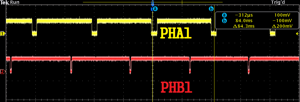
The red pulse is PHA1. The hall sensor's output is 0 when there is a manget in front.

Due to the hall sensor's output, I used the invert mode.

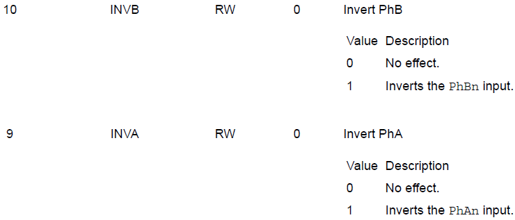
(reference : TM4C123BH6PM datasheet, 1186pg)

However, when I read the QEI position register, it doesn't increase as i expected.

For some reason, it looked like it was reset.

The IDX1 and PHB1 pin is not connected to anything. What might be the problem..?

This is the source code I made. It is a code about printing the qei position to the terminal.

5584.QEI.zip

Always thanks to your help.

-Regards, Min-Ku

  • Hello Min-Ku,

    The QEI modules has two modes of operation:

    Quadrature mode which needs two Signals which are 90degrees out of phase to find the direction and rotation velocity

    Clock/Direction Mode: in which one signal is the pulse and other is direction.

    Based on the code attached you would need to use

    QEI_CONFIG_CLOCK_DIR instead of QEI_CONFIG_QUADRATURE during configuration and connect PhB1 to the other signal (if it is indicating the direction of rotation)

    Regards

    Amit

  • Hello Amit,

    Thanks for the tip. Changing to CLOCK_DIR mode gave some results.

    I printed the QEI position to the terminal and the position value decreases from the max pos value 9000.

    As you metioned, I added another Hall sensor(same product) to PHB1.

    Using the oscilloscope, the the Hall sensors were working quite(?) fine.

    (Each pulses' length of '0' was different. I couldn't find the reason)

    The picture above are the inputs to PHA1 and PHB1 respectively

    while the wheel rotates with 20% of the PWM's duty.

    This is how the car, hall sensors, and the magnet are composed.

    The rear wheel is attached to a magnet and two hall sensors sense the magnet.

    The right side hall sensor's output is connected to PHA1.

    Plus, when the car moves straight, this wheel moves clock-wise from this picture's view.

    I thought managing the sensors like this would be compatible to QUADRATURE mode.

    (ref : TM4C123BH6PM datasheet page 1182)

    Doesn't the pulse from the oscilloscope follows the pulse above?

    I'm having trouble to understand what signal mode to use...

    Can you explain me what's the difference of these two modes?

    1. Code with quad mode, doesn't work

    #include <stdbool.h>
    #include <stdint.h>
    #include <math.h>
    
    #define Wheel 0.0225
    
    #define GYRO_WHO_AM_I       0x0F
    #define GYRO_CTRL_REG1       0X20
    #define GYRO_CTRL_REG2       0X21
    #define GYRO_CTRL_REG3       0X22
    #define GYRO_CTRL_REG4       0X23
    #define GYRO_CTRL_REG5       0X24
    #define GYRO_REFERENCE       0X25
    #define OUT_TEMP       		0X26
    #define STATUS_REG			0x27
    #define GYRO_OUT_X_L       	0X28
    #define GYRO_OUT_X_H       	0X29
    #define GYRO_OUT_Y_L       	0X2A
    #define GYRO_OUT_Y_H       	0X2B
    #define GYRO_OUT_Z_L       	0X2C
    #define GYRO_OUT_Z_H       	0X2D
    #define FIFO_CTRL_REG       0X30
    
    #define ACC_WHO_AM_I       0x0F
    #define ACC_CTRL_REG1       0X20
    #define ACC_CTRL_REG2       0X21
    #define ACC_CTRL_REG3       0X22
    #define ACC_CTRL_REG4       0X23
    #define ACC_CTRL_REG5       0X24
    #define ACC_HP_FILTER_RESET 0X25
    #define ACC_REFERENCE       0X26
    #define ACC_STATUS_REG       0X27
    #define ACC_OUT_X_L       0X28
    #define ACC_OUT_X_H       0X29
    #define ACC_OUT_Y_L       0X2A
    #define ACC_OUT_Y_H       0X2B
    #define ACC_OUT_Z_L       0X2C
    #define ACC_OUT_Z_H       0X2D
    #define ACC_INT1_CFG          0X30
    #define ACC_INT1_SRC          0X31
    #define ACC_INT1_THS          0X31
    #define ACC_INT1_DURATION       0X31
    #define ACC_INT2_CFG          0X31
    #define ACC_INT2_SRC          0X31
    #define ACC_INT2_THS          0X31
    #define ACC_INT2_DURATION       0X31
    
    #define ADC_ERR 10
    
    #include "inc/hw_memmap.h"
    #include "inc/hw_types.h"
    #include "inc/hw_gpio.h"
    #include "inc/hw_ints.h"
    
    #include "driverlib/systick.h"
    #include "driverlib/fpu.h"
    #include "driverlib/gpio.h"
    #include "driverlib/pin_map.h"
    #include "driverlib/ssi.h"
    #include "driverlib/sysctl.h"
    #include "driverlib/uart.h"
    #include "driverlib/pwm.h"
    #include "driverlib/adc.h"
    #include "driverlib/timer.h"
    #include "driverlib/interrupt.h"
    #include "driverlib/qei.h"
    
    #include "utils/uartstdio.h"
    
    //#include "Acc_REG.h"
    //#include "Gyro.h"
    
    #define NUM_SSI_DATA 7
    #define N_AVG 100
    #define D_SIZE 1000
    #define AVG 10
    #define ODR 100
    #define ODR_ACC 1000
    #define off 0.1
    #define RAD_TO_DEG 180 / 3.14159265
    
     volatile double Vx, Vy, Vz;
     volatile double Vx_prev, Vy_prev, Vz_prev;
     volatile double X, Y, Z;
    
    
     int16_t state=0;
    
     int freq;
     int k;
     uint32_t i;
    
    //////////////////Acc
    double accXangle, accYangle, accZangle;
    
    // volatile double DataRX[D_SIZE];
    // volatile double DataRY[D_SIZE];
     volatile double DataRZ[D_SIZE];
    
    // volatile double DataMA[D_SIZE];
     volatile double DataMA0, DataMA1;
     volatile double DataGAG[D_SIZE];
     volatile double DataAAG[D_SIZE];
     volatile double DataKAG[D_SIZE];
    
    
     uint32_t Straight=0;
    
     void InitGYRO();
     void InitSSI1();
     void InitConsole();
     void InitACCEL();
     void GetACCEL();
     void GetACCEL_Zero();
     void GetGyro();
     void InitPWM(void);
     void InitADC();
     void GetADC();
     void GetStraight();
     void Turn(int32_t TURN_ANGLE);
     void InitQEI1();
    
    uint32_t pui32DataTx[NUM_SSI_DATA];
    uint32_t pui32DataRx[NUM_SSI_DATA];
    
    uint32_t pui32ADC0Value[1];
    
    int freq = 0;
    int k=0;
    uint32_t i;
    
    ////////ACC
    volatile double Ax=0, Ay=0, Az=0;
    volatile double Ax_prev=0, Ay_prev=0, Az_prev=0;
    volatile double Ax_offset=0,Ay_offset=0;
    
    ////////GYRO
    volatile double Rx=0, Ry=0, Rz=0;
    volatile double Rx_prev=0, Ry_prev=0, Rz_prev=0;
    volatile double Angle=0;
    volatile double AngleR=0;
    
    //volatile double DataRX[D_SIZE] ={0,};
    //volatile double DataRY[D_SIZE] ={0,};
    volatile double DataRZ[D_SIZE] ={0,};
    //volatile double DataMA[D_SIZE] ={0,};
    volatile double DataMA0, DataMA1;
    volatile double DataGAG[D_SIZE] ={0,};
    volatile double DataAAG[D_SIZE] ={0,};
    volatile double DataKAG[D_SIZE] ={0,};
    
    void InitTimerA0(){
    
    	unsigned long period=0;
    
    	SysCtlPeripheralEnable(SYSCTL_PERIPH_TIMER0);
    
    	TimerConfigure(TIMER0_BASE, TIMER_CFG_PERIODIC);
    
    
    	freq = SysCtlClockGet();
    
    	UARTprintf("\nTimer Setting. System Clock Frequency = %d\n", freq);
    	period = (freq / ODR_ACC) /2;
    
    	TimerLoadSet(TIMER0_BASE, TIMER_A, period -1); //ODR = 800Hz
    	IntEnable(INT_TIMER0A);
    	TimerIntEnable(TIMER0_BASE, TIMER_TIMA_TIMEOUT);
    
    }
    
    void Timer0IntHandler(void){
    	TimerIntClear(TIMER0_BASE, TIMER_TIMA_TIMEOUT);
    	IntMasterDisable();
    
    
    	if(state==0){
    
    		Vy = Vy_prev + 0.5*(Ay + Ay_prev)  / ODR_ACC;
    		Y = Y + 0.5*(Vy + Vy_prev) / ODR_ACC;
    
    		Ay_prev = Ay;
    		Vy_prev = Vy;
    
    		Vx = Vx_prev + 0.5*(Ax + Ax_prev) / ODR_ACC;
    		X = X + 0.5*(Vx + Vx_prev) / ODR_ACC;
    
    		//Ax_prev = Ax;
    		Ax_prev = Az;
    		Vx_prev = Vz;
    	}
    
    	else if(state == 1){
    
    	Angle = Angle + (0.5*(DataMA1 + DataMA0) / ODR);
    	AngleR = AngleR + 0.5*Rz/ODR; //(0.5*(Rz + Rz_prev)/ODR);
    	//Vy = Vy_prev + Ay / ODR;
    	//h=getAngle(accYangle, Ry, 1/ODR);
    
    
    	//Ry_prev = Ry;
    	//DataGAG[k]=Angle;
    	//DataAAG[k]=accYangle;
    	DataKAG[k]=AngleR;
    
    	k++;
    	// i++;
    	if(k==D_SIZE-1){
    		k=0;
    	}
    
    	}
    
    	IntMasterEnable();
    
    }
    
    
    int main(void)
    {
        // Set the clocking to run directly from the al crystal/oscillator.
        // TODO: The SYSCTL_XTAL_ value must be changed to match the value of the
        // crystal on your board.
        //
        //SysCtlClockSet(SYSCTL_SYSDIV_1 | SYSCTL_USE_OSC | SYSCTL_OSC_MAIN |
                      // SYSCTL_XTAL_16MHZ);
    	SysCtlClockSet(SYSCTL_SYSDIV_5|SYSCTL_USE_PLL|SYSCTL_XTAL_16MHZ|SYSCTL_OSC_MAIN);
    
        FPUEnable();
        FPULazyStackingEnable();
    
        InitSSI1();
    
        InitConsole();
    
        InitACCEL();
    
        InitGYRO();
    
        GetACCEL_Zero();
    
    	InitTimerA0();
    
    	InitADC();
    
    	GetStraight();
    
    	InitQEI1();
    
        InitPWM();
    
    	//TimerEnable(TIMER0_BASE, TIMER_A);
    
        /*
    
        while(1){
    
        	GetACCEL();
    
        	//UARTprintf("%d %d %d\n",(int)(Ay*1000),(int)(Vy*1000),(int)(Y*1000));
    
        	if(Y <= -2.0)
        		break;
        }
    
        TimerDisable(TIMER0_BASE, TIMER_A);
    
        IntMasterDisable();
    
        TimerLoadSet(TIMER0_BASE, TIMER_A, (freq / ODR) /2 -1); //ODR = 800Hz
    
        TimerIntClear(TIMER0_BASE, TIMER_TIMA_TIMEOUT);
    
        Turn(400);
    
        state = 1;
    
        IntMasterEnable();
        TimerEnable(TIMER0_BASE, TIMER_A);
    
        while(1){
    
        	GetGyro();
    
        	if(AngleR >= 90.0){
        			PWMPulseWidthSet(PWM0_BASE, PWM_OUT_0,
        			                         PWMGenPeriodGet(PWM0_BASE, PWM_OUT_0) / 100);
    
        			Turn(0);
    
        			while(1);
        	}
    
        	//UARTprintf("Rx Ry Rz  : ");
        	//UARTprintf("%3d ",(int)Rz);
        	//UARTprintf(", angle  : %d\n",(int)AngleR);
        }
        */
    
        while(1)
        {
        	UARTprintf("%4d\n",QEIPositionGet(QEI1_BASE));
        	SysCtlDelay (100);
        }
    }
    
    void InitGYRO(){
    
    	uint32_t ui32Index;
    
    	while(SSIDataGetNonBlocking(SSI1_BASE, &pui32DataRx[0]));
    
    	    //
    	    // Initialize the data to send.
    	    //
    	    pui32DataTx[0] = ((GYRO_CTRL_REG1<<8)|0x0F);//write control reg1//ODR=100Hz Cut-off=12.5(band width)
    	    pui32DataTx[1] = ((GYRO_CTRL_REG2<<8)|0x20);//write control reg2//Normal mode Cut-off = 8Hz(high pass)
    	    pui32DataTx[2] = ((GYRO_CTRL_REG4<<8)|0x80);//write control reg4//Block data update,250dps,4-wire interface
    
    	    pui32DataTx[3] = ((GYRO_REFERENCE<<8)|0x00);
    		pui32DataTx[4] = ((GYRO_CTRL_REG5<<8)|0x10);//read control reg1
    	    pui32DataTx[5] = (GYRO_WHO_AM_I|0x80)<<8;//read status reg
    	    pui32DataTx[6] = (STATUS_REG|0x80)<<8;//read status reg
    
    	    //
    	    // Display indication that the SSI is transmitting data.
    	    //
    	    //UARTprintf("Sent:\n  ");
    
    	    //
    	    // Send 3 bytes of data.
    	    //
    	    for(ui32Index = 0; ui32Index < NUM_SSI_DATA; ui32Index++)
    	    {
    	        //
    	        // Display the data that SSI is transferring.
    	        //
    	        UARTprintf("%02x ", pui32DataTx[ui32Index]);
    
    	        //
    	        // Send the data using the "blocking" put function.  This function
    	        // will wait until there is room in the send FIFO before returning.
    	        // This allows you to assure that all the data you send makes it into
    	        // the send FIFO.
    	        //
    	        GPIOPinWrite(GPIO_PORTE_BASE,GPIO_PIN_5,0);
            	SSIDataPut(SSI1_BASE, pui32DataTx[ui32Index]);
    
    			SysCtlDelay(40);
    			GPIOPinWrite(GPIO_PORTE_BASE,GPIO_PIN_5,GPIO_PIN_5);
    	    }
    
    	    //
    	    // Wait until SSI0 is done transferring all the data in the transmit FIFO.
    	    //
    	    while(SSIBusy(SSI1_BASE))
    	    {
    	    }
    
    	    //
    	    // Display indication that the SSI is receiving data.
    	    //
    	    UARTprintf("\nReceived:\n  ");
    
    	    //
    	    // Receive 3 bytes of data.
    	    //
    	    for(ui32Index = 0; ui32Index < NUM_SSI_DATA; ui32Index++)
    	    {
    	        //
    	        // Receive the data using the "blocking" Get function. This function
    	        // will wait until there is data in the receive FIFO before returning.
    	        //
    	        SSIDataGet(SSI1_BASE, &pui32DataRx[ui32Index]);
    
    	        //
    	        // 8-bit data, mask off the MSB.
    	        //
    	        pui32DataRx[ui32Index] &= 0x00FF;
    
    	        //
    	        // Display the data that SSI1 received.
    	        //
    	        UARTprintf("%02x ", pui32DataRx[ui32Index]);
    	    }
    
    	    UARTprintf("\n\n");
    }
    
    
    void InitSSI1(void){
    	SysCtlPeripheralEnable(SYSCTL_PERIPH_SSI1);
    
    	    //
    	    // For this example SSI0 is used with PortF[3:0].  The actual port and pins
    	    // used may be different on your part, consult the data sheet for more
    	    // information.  GPIO port A needs to be enabled so these pins can be used.
    	    // TODO: change this to whichever GPIO port you are using.
    	    //
    	    SysCtlPeripheralEnable(SYSCTL_PERIPH_GPIOF);
    		SysCtlPeripheralEnable(SYSCTL_PERIPH_GPIOE);
    
    	    HWREG(GPIO_PORTF_BASE+GPIO_O_LOCK) = GPIO_LOCK_KEY;
    	    //Unlock the Port to write to commit register
    
    	    HWREG(GPIO_PORTF_BASE+GPIO_O_CR) = 0xFF;
    	    // Set the pins of the commit register so that AFSEL and other registers can be modified
    	    //
    	    //
    	    // This step is not necessary if your part does not support pin muxing.
    	    // TODO: change this to select the port/pin you are using.
    	    //
    	    GPIOPinConfigure(GPIO_PF2_SSI1CLK);
    	    GPIOPinConfigure(GPIO_PF0_SSI1RX);
    	    GPIOPinConfigure(GPIO_PF1_SSI1TX);
    
    	    HWREG(GPIO_PORTF_BASE+GPIO_O_LOCK) = ~(GPIO_LOCK_KEY);
    
    	    //
    	    // Configure the GPIO settings for the SSI pins.  This function also gives
    	    // control of these pins to the SSI hardware.  Consult the data sheet to
    	    // see which functions are allocated per pin.
    	    // The pins are assigned as follows:
    	    //      PF0 - SSI1Rx
    	    //		PF1 - SSI1Tx
    	    //     	PF2 - SSI1CLK
    	    //		PF3 - SSI1Fss
    	    //
    	    //
    	    // TODO: change this to select the port/pin you are using.
    	    //
    	    GPIOPinTypeSSI(GPIO_PORTF_BASE,GPIO_PIN_2 | GPIO_PIN_1 | GPIO_PIN_0);
    
    		GPIOPinTypeGPIOOutput(GPIO_PORTF_BASE, GPIO_PIN_3);//ACC FSS pull-up
    		GPIOPinWrite(GPIO_PORTF_BASE,GPIO_PIN_3,GPIO_PIN_3);
    		GPIOPinTypeGPIOOutput(GPIO_PORTE_BASE, GPIO_PIN_5);//Gyro FSS pull-up
    		GPIOPinWrite(GPIO_PORTE_BASE,GPIO_PIN_5,GPIO_PIN_5);
    
    	    //
    	    // Configure and enable the SSI port for SPI master mode.  Use SSI0,
    	    // system clock supply, idle clock level low and active low clock in
    	    // freescale SPI mode, master mode, 1MHz SSI frequency, and 8-bit data.
    	    // For SPI mode, you can set the polarity of the SSI clock when the SSI
    	    // unit is idle.  You can also configure what clock edge you want to
    	    // capture data on.  Please reference the datasheet for more information on
    	    // the different SPI modes.
    	    //
    	    SSIConfigSetExpClk(SSI1_BASE, SysCtlClockGet(), SSI_FRF_MOTO_MODE_3,
    	                       SSI_MODE_MASTER, 5000000, 16);
    
    	    //
    	    // Enable the SSI0 module.
    	    //
    	    SSIEnable(SSI1_BASE);
    }
    
    
    void InitPWM(void){
    	SysCtlPWMClockSet(SYSCTL_PWMDIV_1);
    
    	SysCtlPeripheralEnable(SYSCTL_PERIPH_PWM0);
    	SysCtlPeripheralEnable(SYSCTL_PERIPH_GPIOB);
    
    	// DC Motor
    	GPIOPinConfigure(GPIO_PB6_M0PWM0);
    	GPIOPinConfigure(GPIO_PB7_M0PWM1);
    
    	//Rotation Motor
    	GPIOPinConfigure(GPIO_PB4_M0PWM2); //Right
    	GPIOPinConfigure(GPIO_PB5_M0PWM3); //Left
    
    	GPIOPinTypeGPIOOutput(GPIO_PORTB_BASE, GPIO_PIN_6);
    	GPIOPinTypeGPIOOutput(GPIO_PORTB_BASE, GPIO_PIN_7);
    
    	GPIOPinTypeGPIOOutput(GPIO_PORTB_BASE, GPIO_PIN_4);
    	GPIOPinTypeGPIOOutput(GPIO_PORTB_BASE, GPIO_PIN_5);
    	//GPIOPinWrite(GPIO_PORTB_BASE,GPIO_PIN_6,0);
    	//GPIOPinWrite(GPIO_PORTB_BASE,GPIO_PIN_7,0);
    
    	GPIOPinTypePWM(GPIO_PORTB_BASE, (GPIO_PIN_4 | GPIO_PIN_5 | GPIO_PIN_6 | GPIO_PIN_7));
    
    	PWMGenConfigure(PWM0_BASE, PWM_GEN_0, PWM_GEN_MODE_UP_DOWN |
    	                        PWM_GEN_MODE_NO_SYNC);
    
    	PWMGenConfigure(PWM0_BASE, PWM_GEN_1, PWM_GEN_MODE_UP_DOWN |
    		                        PWM_GEN_MODE_NO_SYNC);
    
    	    // use the following equation: N = (1 / f) * SysClk.  Where N is the
    	    // Set the PWM period to 250Hz.  To calculate the appropriate parameter
    	    // function parameter, f is the desired frequency, and SysClk is the
    	    // system clock frequency.
    	    // In this case you get: (1 / 250Hz) * 16MHz = 64000 cycles.  Note that
    	    // the maximum period you can set is 2^16.
    	    // TODO: modify this calculation to use the clock frequency that you are
    	    // using.
    	    //
    	//DC Motor Freq Setting
    	PWMGenPeriodSet(PWM0_BASE, PWM_GEN_0, 15000000);
    
    	//Rotation Motor Freq Setting
    	PWMGenPeriodSet(PWM0_BASE, PWM_GEN_1, 100000);
    
    	    // Set PWM0 to a duty cycle of 25%.  You set the duty cycle as a function
    	    // of the period.  Since the period was set above, you can use the
    	    // PWMGenPeriodGet() function.  For this example the PWM will be high for
    	    // 25% of the time or 16000 clock ticks (64000 / 4).
    	    //
    
    	// DC Motor duty setting
    	PWMPulseWidthSet(PWM0_BASE, PWM_OUT_0,
    	                         PWMGenPeriodGet(PWM0_BASE, PWM_OUT_0) / 3);
    
    
    	PWMPulseWidthSet(PWM0_BASE, PWM_OUT_1,
    	                             PWMGenPeriodGet(PWM0_BASE, PWM_OUT_0) / 100000);


    	// Rotation Motor duty setting
    	//PWMPulseWidthSet(PWM0_BASE, PWM_OUT_2,
    		//	10000 / 8000); //Right
    
    	PWMPulseWidthSet(PWM0_BASE, PWM_OUT_2,
    			100000 / 10000); //Right
    
    	PWMPulseWidthSet(PWM0_BASE, PWM_OUT_3,
    			100000 / 10000); //Left
    
    
    	PWMOutputState(PWM0_BASE, PWM_OUT_0_BIT, true);
    	PWMOutputState(PWM0_BASE, PWM_OUT_1_BIT, true);
    
    	PWMOutputState(PWM0_BASE, PWM_OUT_2_BIT, true);
    	PWMOutputState(PWM0_BASE, PWM_OUT_3_BIT, true);
    
    	PWMGenEnable(PWM0_BASE, PWM_GEN_0);
    	PWMGenEnable(PWM0_BASE, PWM_GEN_1);
    
    	UARTprintf("PWM ->\n");
    	UARTprintf("  Module: PWM0\n");
    	UARTprintf("  Pin: PB6, PB7(DC Motor) , PB4, PB5(Rotation Motor)\n");
    	   // Display the setup on the console.
    	    //
           //
    }
    
    
    void GetGyro(){
    
    
      uint32_t ui32Index;
      int16_t ax=0,ay=0,az=0;
      double ix=0,iy=0,iz=0;
      //uint32_t i=0;
      uint32_t j=0;
      double SUM=0;
    
      SysCtlDelay(35);
    
      //del_t = TimerValueGet(TIMER0_BASE,TIMER_A);
    
        //for(i=0;i<100;i++){
    
      while(SSIDataGetNonBlocking(SSI1_BASE, &pui32DataRx[0]));
    
          //
          // Initialize the data to send.
          //
    
    
          pui32DataTx[0] = (GYRO_OUT_X_H|0x80)<<8;//read X high
          pui32DataTx[1] = (GYRO_OUT_X_L|0x80)<<8;//read X Low
    
          pui32DataTx[2] = (GYRO_OUT_Y_H|0x80)<<8;//read Y high
          pui32DataTx[3] = (GYRO_OUT_Y_L|0x80)<<8;//read Y Low
    
          pui32DataTx[4] = (GYRO_OUT_Z_H|0x80)<<8;//read Z high
          pui32DataTx[5] = (GYRO_OUT_Z_L|0x80)<<8;//read Z Low
          pui32DataTx[6] = (STATUS_REG|0x80)<<8; //read Status_Reg
    
    
          //
          // Display indication that the SSI is transmitting data.
          //
    
          //UARTprintf("Sent: ");
    
          //
          //
          for(ui32Index = 0; ui32Index < NUM_SSI_DATA; ui32Index++)
          {
              //
              // Display the data that SSI is transferring.
              //
              //UARTprintf("%02x ", pui32DataTx[ui32Index]);
             //SysCtlDelay(50);
    
              //
              // Send the data using the "blocking" put function.  This function
              // will wait until there is room in the send FIFO before returning.
              // This allows you to assure that all the data you send makes it into
              // the send FIFO.
              //
            GPIOPinWrite(GPIO_PORTE_BASE, GPIO_PIN_5, 0);
              SSIDataPut(SSI1_BASE, pui32DataTx[ui32Index]);
    
            SysCtlDelay(40);
            GPIOPinWrite(GPIO_PORTE_BASE,GPIO_PIN_5,GPIO_PIN_5);
          }
    
          //
          // Wait until SSI1 is done transferring all the data in the transmit FIFO.
          //
          while(SSIBusy(SSI1_BASE))
          {
          }
    
          //
          // Display indication that the SSI is receiving data.
          //
          //UARTprintf("\nRecieve : ");
    
          for(ui32Index = 0; ui32Index < NUM_SSI_DATA; ui32Index++)
          {
              //
              // Receive the data using the "blocking" Get function. This function
              // will wait until there is data in the receive FIFO before returning.
              //
              SSIDataGet(SSI1_BASE, &pui32DataRx[ui32Index]);
    
              //
              // Since we are using 8-bit data, mask off the MSB.
              //
              pui32DataRx[ui32Index] &= 0x00FF;
    
              //
              // Display the data that SSI0 received.
              //
              //UARTprintf("%02x ", pui32DataRx[ui32Index]);
              //SysCtlDelay(50);
          }
    
          ax = (int16_t) ((((pui32DataRx[0]<<8) | pui32DataRx[1])));
          ay = (int16_t) ((((pui32DataRx[2]<<8) | pui32DataRx[3])));
          az = (int16_t) ((((pui32DataRx[4]<<8) | pui32DataRx[5])));
    
    
          //16bit representation
    
          ix = (double)((ax)*(8.75));
          iy = (double)((ay)*(8.75));
          iz = (double)((az)*(8.75));
    
          //if(i==0){
    
             // del_t  = TimerValueGet(TIMER0_BASE,TIMER_A) - del_t;
              //dt = (double)( del_t / freq );
    
            //}
    
          //lx =;
    
          // * 49 * 9.8
    
          //UARTprintf(" / %4d %4d %4d ", ax,ay,az);
          //UARTprintf(" / %6d %6d %6d ", ix,iy,iz);
          //UARTprintf("\n");
          //UARTprintf("\r");
    
          Rx = (double)(ix)/1000;//1;
          Ry = (double)(iy)/1000;
          Rz = (double)(iz)/1000-0.5;
    
    
          //DataRX[i] = Rx;
           //DataRY[i] = Ry;
           DataRZ[i] = Rz;
    
           /*if(i>98){
              for(j=i-99; j<i+1; j++){
              SUM+=DataRZ[j];
              }
                DataMA[i]=SUM/100;
           }*/
    
           SUM=0;
    
           if(i>AVG-2){
              for(j=i-(AVG-1); j<i+1; j++)
                 SUM+=DataRZ[j];
           }
    
           else{
    
              for(j=0;j<i+1;j++)
                 SUM += DataRZ[j];
    
              for(j=D_SIZE-AVG+1+i;j<D_SIZE;j++)
                 SUM += DataRZ[j];
           }
    
           DataMA0=DataMA1;
           DataAAG[i] = DataMA0;
           DataMA1=SUM/AVG;
    
         //Rx_prev = Rx;
         //Ry_prev = Ry;
           Rz_prev = Rz;
         // }
         i++;
    
         if(i>D_SIZE-1)
            i=0;
    }
    
    void GetACCEL(){
    
    	   uint32_t ui32Index;
    	   int16_t ax=0,ay=0,az=0;
    	   uint16_t XYZDA=0;
    	   uint16_t TT=1;
    
    	   while(1){
    
    	   	       while(SSIDataGetNonBlocking(SSI1_BASE, &pui32DataRx[0]));
    
    	   	       //
    	   	       // Initialize the data to send.
    	   	       //
    
    	   	       pui32DataTx[0] = (ACC_STATUS_REG|0x80)<<8;//read X high
    
    	   	       pui32DataTx[1] = (ACC_OUT_X_H|0x80)<<8;//read X high
    	   	       pui32DataTx[2] = (ACC_OUT_X_L|0x80)<<8;//read X Low
    
    	   	       pui32DataTx[3] = (ACC_OUT_Y_H|0x80)<<8;//read Y high
    	   	       pui32DataTx[4] = (ACC_OUT_Y_L|0x80)<<8;//read Y Low
    
    	   	       pui32DataTx[5] = (ACC_OUT_Z_H|0x80)<<8;//read Z high
    	   	       pui32DataTx[6] = (ACC_OUT_Z_L|0x80)<<8;//read Z Low
    	   	       //
    	   	       // Display indication that the SSI is transmitting data.
    	   	       //
    
    	   	       //UARTprintf("Sent: ");
    
    	   	       //
    	   	       for(ui32Index = 0; ui32Index < NUM_SSI_DATA; ui32Index++)
    	   	       {
    	   	           //
    	   	           // Display the data that SSI is transferring.
    	   	           //
    	   	           //UARTprintf("%02x ", pui32DataTx[ui32Index]);
    
    
    	   	           //
    	   	           // Send the data using the "blocking" put function.  This function
    	   	           // will wait until there is room in the send FIFO before returning.
    	   	           // This allows you to assure that all the data you send makes it into
    	   	           // the send FIFO.
    	   	           //
    	   	          GPIOPinWrite(GPIO_PORTF_BASE,GPIO_PIN_3,0);
    	   			  SSIDataPut(SSI1_BASE, pui32DataTx[ui32Index]);
    
    	   			  SysCtlDelay(35);
    	   			  GPIOPinWrite(GPIO_PORTF_BASE,GPIO_PIN_3,GPIO_PIN_3);
    	   	       }
    
    	   	       //
    	   	       // Wait until SSI1 is done transferring all the data in the transmit FIFO.
    	   	       //
    	   	       while(SSIBusy(SSI1_BASE));
    
    	   	       //
    	   	       // Display indication that the SSI is receiving data.
    	   	       //
    	   	       //UARTprintf(" : ");
    
    	   	       for(ui32Index = 0; ui32Index < NUM_SSI_DATA; ui32Index++)
    	   	       {
    	   	           //
    	   	           // Receive the data using the "blocking" Get function. This function
    	   	           // will wait until there is data in the receive FIFO before returning.
    	   	           //
    	   	           SSIDataGet(SSI1_BASE, &pui32DataRx[ui32Index]);
    
    	   	           //
    	   	           // Since we are using 8-bit data, mask off the MSB.
    	   	           //
    	   	           pui32DataRx[ui32Index] &= 0x00FF;
    
    	   	           //
    	   	           // Display the data that SSI0 received.
    	   	           //
    	   	           //UARTprintf("%02x ", pui32DataRx[ui32Index]);
    	   	           SysCtlDelay(35);
    	   	       }
    
    	   	       XYZDA = pui32DataRx[0] & 0x08;
    
    	   	       if(XYZDA == 0x08){ //bit3, ZYXDA bit
    	   	    	   ax = (int16_t) ((((pui32DataRx[1]<<8) | pui32DataRx[2]))) >>4;
    	   	    	   ay = (int16_t) ((((pui32DataRx[3]<<8) | pui32DataRx[4]))) >>4;
    	   	    	   az = (int16_t) ((((pui32DataRx[5]<<8) | pui32DataRx[6]))) >>4;
    	   	    	   //12bit representation
    	   	    	   // * 49 * 9.8
    
    	   	    	   Ax = (double)(((ax)*(3.9 * 9.8))/1000) - Ax_offset;
    	   	    	   Ay = (double)(((ay)*(3.9 * 9.8))/1000) - Ay_offset; //zero offset
    	   	    	   Az = (double)(((az)*(3.9 * 9.8))/1000);
    
    	   	    	   Vy = Vy_prev + 0.5 * TT *(Ay + Ay_prev)  / ODR_ACC;
    	   	    	   Y = Y + 0.5 * TT *(Vy + Vy_prev) / ODR_ACC;
    
    	   	    	   Ay_prev = Ay;
    	   	    	   Vy_prev = Vy;
    
    	   	    	   Vx = Vx_prev + 0.5 * TT *(Ax + Ax_prev) / ODR_ACC;
    	   	    	   X = X + 0.5 * TT *(Vx + Vx_prev) / ODR_ACC;
    
    	   	    	   Ax_prev = Az;
    	   	    	   Vx_prev = Vz;
    
    	   	    	   break;
    	   	       }
    
    	   	       TT++;
    	   	   }
    
    	   	   XYZDA = 0;
    }
    
    
    void InitACCEL(){
    	   uint32_t ui32Index;
    
    	   while(SSIDataGetNonBlocking(SSI1_BASE, &pui32DataRx[0]));
    
    	       //
    	       // Initialize the data to send.
    	       //
    	       pui32DataTx[0] = ((ACC_CTRL_REG1<<8)|0x3F);//write control reg1
    	       pui32DataTx[1] = ((ACC_CTRL_REG2<<8)|0x33);//write control reg2
    	       //pui32DataTx[2] = ((ACC_CTRL_REG4<<8)|0x80);//write control reg4, 2g
    	       pui32DataTx[2] = ((ACC_CTRL_REG4<<8)|0xB0);//write control reg4, 8g
    
    	       pui32DataTx[3] = ((ACC_REFERENCE<<8)|0x00);
    
    	       pui32DataTx[4] = (ACC_WHO_AM_I|0x80)<<8;//read status reg
    	       pui32DataTx[5] = (ACC_CTRL_REG1|0x80)<<8;//read control reg1
    	       pui32DataTx[6] = (ACC_STATUS_REG|0x80)<<8;//read status reg1
    
    	       //
    	       // Display indication that the SSI is transmitting data.
    	       //
    	       UARTprintf("Sent:\n  ");
    
    	       //
    	       // Send 3 bytes of data.
    	       //
    	       for(ui32Index = 0; ui32Index < NUM_SSI_DATA; ui32Index++)
    	       {
    	           //
    	           // Display the data that SSI is transferring.
    	           //
    	           UARTprintf("%02x ", pui32DataTx[ui32Index]);
    
    	           //
    	           // Send the data using the "blocking" put function.  This function
    	           // will wait until there is room in the send FIFO before returning.
    	           // This allows you to assure that all the data you send makes it into
    	           // the send FIFO.
    	           //
    			  GPIOPinWrite(GPIO_PORTF_BASE,GPIO_PIN_3,0);
    			  SSIDataPut(SSI1_BASE, pui32DataTx[ui32Index]);
    
    			  SysCtlDelay(100);
    			  GPIOPinWrite(GPIO_PORTF_BASE,GPIO_PIN_3,GPIO_PIN_3);
    	       }
    
    	       //
    	       // Wait until SSI0 is done transferring all the data in the transmit FIFO.
    	       //
    	       while(SSIBusy(SSI1_BASE))
    	       {
    	       }
    
    	       //
    	       // Display indication that the SSI is receiving data.
    	       //
    	       UARTprintf("\nReceived:\n  ");
    
    	       //
    	       // Receive 3 bytes of data.
    	       //
    	       for(ui32Index = 0; ui32Index < NUM_SSI_DATA; ui32Index++)
    	       {
    	           //
    	           // Receive the data using the "blocking" Get function. This function
    	           // will wait until there is data in the receive FIFO before returning.
    	           //
    	           SSIDataGet(SSI1_BASE, &pui32DataRx[ui32Index]);
    
    	           //
    	           // 8-bit data, mask off the MSB.
    	           //
    	           pui32DataRx[ui32Index] &= 0x00FF;
    
    	           //
    	           // Display the data that SSI1 received.
    	           //
    	           UARTprintf("%02x ", pui32DataRx[ui32Index]);
    	       }
    
    	       UARTprintf("\n");
    }


    void InitConsole(void)
    {
        //
        // Enable GPIO port A which is used for UART0 pins.
        // TODO: change this to whichever GPIO port you are using.
        //
        SysCtlPeripheralEnable(SYSCTL_PERIPH_GPIOA);
    
        //
        // Configure the pin muxing for UART0 functions on port A0 and A1.
        // This step is not necessary if your part does not support pin muxing.
        // TODO: change this to select the port/pin you are using.
        //
        GPIOPinConfigure(GPIO_PA0_U0RX);
        GPIOPinConfigure(GPIO_PA1_U0TX);
    
        //
        // Enable UART0 so that we can configure the clock.
        //
        SysCtlPeripheralEnable(SYSCTL_PERIPH_UART0);
    
        //
        // Use the internal 16MHz oscillator as the UART clock source.
        //
        UARTClockSourceSet(UART0_BASE, UART_CLOCK_PIOSC);
    
        //
        // Select the alternate (UART) function for these pins.
        // TODO: change this to select the port/pin you are using.
        //
        GPIOPinTypeUART(GPIO_PORTA_BASE, GPIO_PIN_0 | GPIO_PIN_1);
    
        //
        // Initialize the UART for console I/O.
        //
        UARTStdioConfig(0, 115200, 16000000);
    }
    
    void InitADC(){
    
        SysCtlPeripheralEnable(SYSCTL_PERIPH_ADC0);
        SysCtlPeripheralEnable(SYSCTL_PERIPH_GPIOE);
        GPIOPinTypeADC(GPIO_PORTE_BASE, GPIO_PIN_3);
    
        // Enable sample sequence 3 with a processor signal trigger.  Sequence 3
            // will do a single sample when the processor sends a signal to start the
            // conversion.  Each ADC module has 4 programmable sequences, sequence 0
            // to sequence 3.  This example is arbitrarily using sequence 3.
            //
        ADCSequenceConfigure(ADC0_BASE, 3, ADC_TRIGGER_PROCESSOR, 0);
    
            //
            // Configure step 0 on sequence 3.  Sample channel 0 (ADC_CTL_CH0) in
            // single-ended mode (default) and configure the interrupt flag
            // (ADC_CTL_IE) to be set when the sample is done.  Tell the ADC logic
            // that this is the last conversion on sequence 3 (ADC_CTL_END).  Sequence
            // 3 has only one programmable step.  Sequence 1 and 2 have 4 steps, and
            // sequence 0 has 8 programmable steps.  Since we are only doing a single
            // conversion using sequence 3 we will only configure step 0.  For more
            // information on the ADC sequences and steps, reference the datasheet.
            //
        ADCSequenceStepConfigure(ADC0_BASE, 3, 0, ADC_CTL_CH0 | ADC_CTL_IE |
                                     ADC_CTL_END);
    
            //
            // Since sample sequence 3 is now configured, it must be enabled.
            //
        ADCSequenceEnable(ADC0_BASE, 3);
        ADCIntClear(ADC0_BASE, 3);
    
    	UARTprintf("ADC ->\n");
    	UARTprintf("  Type: Single Ended\n");
    	UARTprintf("  Samples: One\n");
    	UARTprintf("  Update Rate: 250ms\n");
    	UARTprintf("  Input Pin: AIN0/PE3\n\n");
    }
    
    void GetADC(){
    
    	ADCProcessorTrigger(ADC0_BASE, 3);
    
    	 //
    	 // Wait for conversion to be completed.
         while(!ADCIntStatus(ADC0_BASE, 3, false));
    
    	        //
    	        // Clear the ADC interrupt flag.
    	        //
    	 ADCIntClear(ADC0_BASE, 3);
    
    	        //
    	        // Read ADC Value.
    	        //
    	 ADCSequenceDataGet(ADC0_BASE, 3, pui32ADC0Value);
    
    	        //
    	        // Display the AIN0 (PE7) digital value on the console.
    	        //
    	 UARTprintf("AIN0 = %4d\r", pui32ADC0Value[0]);
    
    	        //
    	        // This function provides a means of generating a constant length
    	        // delay.  The function delay (in cycles) = 3 * parameter.  Delay
    	        // 250ms arbitrarily.
    	        //
    	 SysCtlDelay(freq / 1250);
    }
    
    
    void GetStraight(){
    
    	ADCProcessorTrigger(ADC0_BASE, 3);
    
    	 //
    	 // Wait for conversion to be completed.
         while(!ADCIntStatus(ADC0_BASE, 3, false));
    
    	        //
    	        // Clear the ADC interrupt flag.
    	        //
    	 ADCIntClear(ADC0_BASE, 3);
    
    	        //
    	        // Read ADC Value.
    	        //
    	 ADCSequenceDataGet(ADC0_BASE, 3, pui32ADC0Value);
    
    	        //
    	        // Display the AIN0 (PE7) digital value on the console.
    	        //
    	 UARTprintf("Straight = %4d\n\n", pui32ADC0Value[0]);
    
    	 Straight = pui32ADC0Value[0];
    
    	        //
    	        // This function provides a means of generating a constant length
    	        // delay.  The function delay (in cycles) = 3 * parameter.  Delay
    	        // 250ms arbitrarily.
    	        //
    	 SysCtlDelay(freq / 1250);
    
    
    }
    
    void Turn(int32_t TURN_ANGLE){
    
    	uint32_t Prev_ADC;
    	int32_t del;
    
    	UARTprintf("\nTurn %d\n", TURN_ANGLE);
    
    	while(1){
    
    
    		GetADC();
    
    		Prev_ADC = pui32ADC0Value[0] - Straight;
    		del = TURN_ANGLE - Prev_ADC;
    
    		if(del < ADC_ERR && (-1)*ADC_ERR < del){
    
    			PWMPulseWidthSet(PWM0_BASE, PWM_OUT_2,
    						100000 / 10000); //Right
    
    			PWMPulseWidthSet(PWM0_BASE, PWM_OUT_3,
    						100000 / 10000); //Left
    
    			break;
    		}
    
    		if(del>0){//Left
    
    			PWMPulseWidthSet(PWM0_BASE, PWM_OUT_2,
    									100000 / 10000); //Right
    
    			PWMPulseWidthSet(PWM0_BASE, PWM_OUT_3,
    									100000 / 6); //Left
    		}
    
    		else{//Right
    
    			PWMPulseWidthSet(PWM0_BASE, PWM_OUT_2,
    												100000 / 6); //Right
    
    			PWMPulseWidthSet(PWM0_BASE, PWM_OUT_3,
    												100000 / 10000); //Left
    		}
    	}
    }
    
    void GetACCEL_Zero(){
    	uint32_t ui32Index;
    	int16_t ax=0,ay=0;
    	double ix=0,iy=0;
    	uint16_t XYZDA=0;
    
    	short count=0;
    	short Limit=100;
    
    	for(count=0;count<Limit;count++){
    
    		   while(1){
    
    		   	       while(SSIDataGetNonBlocking(SSI1_BASE, &pui32DataRx[0]));
    
    		   	       //
    		   	       // Initialize the data to send.
    		   	       //
    
    		   	       pui32DataTx[0] = (ACC_STATUS_REG|0x80)<<8;//read X high
    
    		   	       pui32DataTx[1] = (ACC_OUT_X_H|0x80)<<8;//read X high
    		   	       pui32DataTx[2] = (ACC_OUT_X_L|0x80)<<8;//read X Low
    
    		   	       pui32DataTx[3] = (ACC_OUT_Y_H|0x80)<<8;//read Y high
    		   	       pui32DataTx[4] = (ACC_OUT_Y_L|0x80)<<8;//read Y Low
    
    		   	       //pui32DataTx[5] = (ACC_OUT_Z_H|0x80)<<8;//read Z high
    		   	       //pui32DataTx[6] = (ACC_OUT_Z_L|0x80)<<8;//read Z Low
    		   	       //
    		   	       // Display indication that the SSI is transmitting data.
    		   	       //
    
    		   	       //UARTprintf("Sent: ");
    
    		   	       //
    		   	       for(ui32Index = 0; ui32Index < 5; ui32Index++)
    		   	       {
    		   	           //
    		   	           // Display the data that SSI is transferring.
    		   	           //
    		   	           //UARTprintf("%02x ", pui32DataTx[ui32Index]);
    
    
    		   	           //
    		   	           // Send the data using the "blocking" put function.  This function
    		   	           // will wait until there is room in the send FIFO before returning.
    		   	           // This allows you to assure that all the data you send makes it into
    		   	           // the send FIFO.
    		   	           //
    		   	          GPIOPinWrite(GPIO_PORTF_BASE,GPIO_PIN_3,0);
    		   			  SSIDataPut(SSI1_BASE, pui32DataTx[ui32Index]);
    
    		   			  SysCtlDelay(35);
    		   			  GPIOPinWrite(GPIO_PORTF_BASE,GPIO_PIN_3,GPIO_PIN_3);
    		   	       }
    
    		   	       //
    		   	       // Wait until SSI1 is done transferring all the data in the transmit FIFO.
    		   	       //
    		   	       while(SSIBusy(SSI1_BASE));
    
    		   	       //
    		   	       // Display indication that the SSI is receiving data.
    		   	       //
    		   	       //UARTprintf(" : ");
    
    		   	       for(ui32Index = 0; ui32Index < 5; ui32Index++)
    		   	       {
    		   	           //
    		   	           // Receive the data using the "blocking" Get function. This function
    		   	           // will wait until there is data in the receive FIFO before returning.
    		   	           //
    		   	           SSIDataGet(SSI1_BASE, &pui32DataRx[ui32Index]);
    
    		   	           //
    		   	           // Since we are using 8-bit data, mask off the MSB.
    		   	           //
    		   	           pui32DataRx[ui32Index] &= 0x00FF;
    
    		   	           //
    		   	           // Display the data that SSI0 received.
    		   	           //
    		   	           //UARTprintf("%02x ", pui32DataRx[ui32Index]);
    		   	           SysCtlDelay(35);
    		   	       }
    
    		   	       XYZDA = pui32DataRx[0] & 0x08;
    
    		   	       if(XYZDA == 0x08){ //bit3, ZYXDA bit
    
    		   	       ax = (int16_t) ((((pui32DataRx[1]<<8) | pui32DataRx[2]))) >>4;
    		   	       ay = (int16_t) ((((pui32DataRx[3]<<8) | pui32DataRx[4]))) >>4;
    		   	       //12bit representation
    
    		   	       ix = (float)((ax)*(3.9 * 9.8));
    		   	       iy = (float)((ay)*(3.9 * 9.8));
    
    		   	       // * 49 * 9.8
    
    		   	       //UARTprintf(" / %4d %4d %4d ", ax,ay,az);
    		   	       //UARTprintf(" / %6d %6d %6d ", ix,iy,iz);
    		   	       //UARTprintf("\n");
    		   	       //UARTprintf("\r");
    
    		   	       //Ax = (float)(ix/1000) - Offset_X;
    		   	       //Ay = (float)(iy/1000) - Offset_Y;
    		   	    Ax_offset += (float)(ix/1000);
    		   	    Ay_offset += (float)(iy/1000); //zero offset
    
    		   	       break;
    		   	       }
    		   	   }
    
    		   	   XYZDA = 0;
    	}
    
    	Ax_offset = Ax_offset / Limit;
    	Ay_offset = Ay_offset / Limit;
    
    	UARTprintf("\nAccel Zero offset X = %d/1000, Y = %d/1000\n", (int)(Ax_offset*1000),(int)(Ay_offset*1000));
    
    }
    
    void InitQEI1(){
    
    	short initpos = 0;
    	uint32_t MaxPos = 1600000000;
    
    
    	SysCtlPeripheralEnable(SYSCTL_PERIPH_GPIOC);
    	SysCtlPeripheralEnable(SYSCTL_PERIPH_QEI1);
    
    	HWREG(GPIO_PORTC_BASE + GPIO_O_LOCK) = GPIO_LOCK_KEY;
    
    	HWREG(GPIO_PORTC_BASE + GPIO_O_CR) |= 0xF0;
    	//PC4, PC5, PC6
    	HWREG(GPIO_PORTC_BASE + GPIO_O_LOCK) = 0;
    
    	GPIOPinConfigure(GPIO_PC4_IDX1);
    	GPIOPinConfigure(GPIO_PC5_PHA1);
    	GPIOPinConfigure(GPIO_PC6_PHB1);
    
    	GPIOPinTypeQEI(GPIO_PORTC_BASE, GPIO_PIN_6 |  GPIO_PIN_5|  GPIO_PIN_4);
    
    	QEIDisable(QEI1_BASE);
    	QEIIntDisable(QEI1_BASE,QEI_INTERROR | QEI_INTDIR | QEI_INTTIMER | QEI_INTINDEX);
    
    	QEIConfigure(QEI1_BASE
    			,(QEI_CONFIG_CAPTURE_A_B | QEI_CONFIG_NO_RESET|QEI_CONFIG_QUADRATURE|QEI_CONFIG_NO_SWAP|0x02600)
    			,MaxPos);
    
    	QEIPositionSet(QEI1_BASE, initpos);
    
    	UARTprintf("\nQEI 1 Module Enable\nPosition set to %d\n\n",initpos);
    
    	QEIEnable(QEI1_BASE);
    
    }
    

    2. Code with your tip, using DIR, Clock mode with swapping inputs,

        the QEI pos increases (quite) lineary.

    #include <stdbool.h>
    #include <stdint.h>
    #include <math.h>
    
    #define Wheel 0.0225
    
    #define GYRO_WHO_AM_I       0x0F
    #define GYRO_CTRL_REG1       0X20
    #define GYRO_CTRL_REG2       0X21
    #define GYRO_CTRL_REG3       0X22
    #define GYRO_CTRL_REG4       0X23
    #define GYRO_CTRL_REG5       0X24
    #define GYRO_REFERENCE       0X25
    #define OUT_TEMP       		0X26
    #define STATUS_REG			0x27
    #define GYRO_OUT_X_L       	0X28
    #define GYRO_OUT_X_H       	0X29
    #define GYRO_OUT_Y_L       	0X2A
    #define GYRO_OUT_Y_H       	0X2B
    #define GYRO_OUT_Z_L       	0X2C
    #define GYRO_OUT_Z_H       	0X2D
    #define FIFO_CTRL_REG       0X30
    
    #define ACC_WHO_AM_I       0x0F
    #define ACC_CTRL_REG1       0X20
    #define ACC_CTRL_REG2       0X21
    #define ACC_CTRL_REG3       0X22
    #define ACC_CTRL_REG4       0X23
    #define ACC_CTRL_REG5       0X24
    #define ACC_HP_FILTER_RESET 0X25
    #define ACC_REFERENCE       0X26
    #define ACC_STATUS_REG       0X27
    #define ACC_OUT_X_L       0X28
    #define ACC_OUT_X_H       0X29
    #define ACC_OUT_Y_L       0X2A
    #define ACC_OUT_Y_H       0X2B
    #define ACC_OUT_Z_L       0X2C
    #define ACC_OUT_Z_H       0X2D
    #define ACC_INT1_CFG          0X30
    #define ACC_INT1_SRC          0X31
    #define ACC_INT1_THS          0X31
    #define ACC_INT1_DURATION       0X31
    #define ACC_INT2_CFG          0X31
    #define ACC_INT2_SRC          0X31
    #define ACC_INT2_THS          0X31
    #define ACC_INT2_DURATION       0X31
    
    #define ADC_ERR 10
    
    #include "inc/hw_memmap.h"
    #include "inc/hw_types.h"
    #include "inc/hw_gpio.h"
    #include "inc/hw_ints.h"
    
    #include "driverlib/systick.h"
    #include "driverlib/fpu.h"
    #include "driverlib/gpio.h"
    #include "driverlib/pin_map.h"
    #include "driverlib/ssi.h"
    #include "driverlib/sysctl.h"
    #include "driverlib/uart.h"
    #include "driverlib/pwm.h"
    #include "driverlib/adc.h"
    #include "driverlib/timer.h"
    #include "driverlib/interrupt.h"
    #include "driverlib/qei.h"
    
    #include "utils/uartstdio.h"
    
    //#include "Acc_REG.h"
    //#include "Gyro.h"
    
    #define NUM_SSI_DATA 7
    #define N_AVG 100
    #define D_SIZE 1000
    #define AVG 10
    #define ODR 100
    #define ODR_ACC 1000
    #define off 0.1
    #define RAD_TO_DEG 180 / 3.14159265
    
     volatile double Vx, Vy, Vz;
     volatile double Vx_prev, Vy_prev, Vz_prev;
     volatile double X, Y, Z;
    
    
     int16_t state=0;
    
     int freq;
     int k;
     uint32_t i;
    
    //////////////////Acc
    double accXangle, accYangle, accZangle;
    
    // volatile double DataRX[D_SIZE];
    // volatile double DataRY[D_SIZE];
     volatile double DataRZ[D_SIZE];
    
    // volatile double DataMA[D_SIZE];
     volatile double DataMA0, DataMA1;
     volatile double DataGAG[D_SIZE];
     volatile double DataAAG[D_SIZE];
     volatile double DataKAG[D_SIZE];
    
    
     uint32_t Straight=0;
    
     void InitGYRO();
     void InitSSI1();
     void InitConsole();
     void InitACCEL();
     void GetACCEL();
     void GetACCEL_Zero();
     void GetGyro();
     void InitPWM(void);
     void InitADC();
     void GetADC();
     void GetStraight();
     void Turn(int32_t TURN_ANGLE);
     void InitQEI1();
    
    uint32_t pui32DataTx[NUM_SSI_DATA];
    uint32_t pui32DataRx[NUM_SSI_DATA];
    
    uint32_t pui32ADC0Value[1];
    
    int freq = 0;
    int k=0;
    uint32_t i;
    
    ////////ACC
    volatile double Ax=0, Ay=0, Az=0;
    volatile double Ax_prev=0, Ay_prev=0, Az_prev=0;
    volatile double Ax_offset=0,Ay_offset=0;
    
    ////////GYRO
    volatile double Rx=0, Ry=0, Rz=0;
    volatile double Rx_prev=0, Ry_prev=0, Rz_prev=0;
    volatile double Angle=0;
    volatile double AngleR=0;
    
    //volatile double DataRX[D_SIZE] ={0,};
    //volatile double DataRY[D_SIZE] ={0,};
    volatile double DataRZ[D_SIZE] ={0,};
    //volatile double DataMA[D_SIZE] ={0,};
    volatile double DataMA0, DataMA1;
    volatile double DataGAG[D_SIZE] ={0,};
    volatile double DataAAG[D_SIZE] ={0,};
    volatile double DataKAG[D_SIZE] ={0,};
    
    void InitTimerA0(){
    
    	unsigned long period=0;
    
    	SysCtlPeripheralEnable(SYSCTL_PERIPH_TIMER0);
    
    	TimerConfigure(TIMER0_BASE, TIMER_CFG_PERIODIC);
    
    
    	freq = SysCtlClockGet();
    
    	UARTprintf("\nTimer Setting. System Clock Frequency = %d\n", freq);
    	period = (freq / ODR_ACC) /2;
    
    	TimerLoadSet(TIMER0_BASE, TIMER_A, period -1); //ODR = 800Hz
    	IntEnable(INT_TIMER0A);
    	TimerIntEnable(TIMER0_BASE, TIMER_TIMA_TIMEOUT);
    
    }
    
    void Timer0IntHandler(void){
    	TimerIntClear(TIMER0_BASE, TIMER_TIMA_TIMEOUT);
    	IntMasterDisable();
    
    
    	if(state==0){
    
    		Vy = Vy_prev + 0.5*(Ay + Ay_prev)  / ODR_ACC;
    		Y = Y + 0.5*(Vy + Vy_prev) / ODR_ACC;
    
    		Ay_prev = Ay;
    		Vy_prev = Vy;
    
    		Vx = Vx_prev + 0.5*(Ax + Ax_prev) / ODR_ACC;
    		X = X + 0.5*(Vx + Vx_prev) / ODR_ACC;
    
    		//Ax_prev = Ax;
    		Ax_prev = Az;
    		Vx_prev = Vz;
    	}
    
    	else if(state == 1){
    
    	Angle = Angle + (0.5*(DataMA1 + DataMA0) / ODR);
    	AngleR = AngleR + 0.5*Rz/ODR; //(0.5*(Rz + Rz_prev)/ODR);
    	//Vy = Vy_prev + Ay / ODR;
    	//h=getAngle(accYangle, Ry, 1/ODR);
    
    
    	//Ry_prev = Ry;
    	//DataGAG[k]=Angle;
    	//DataAAG[k]=accYangle;
    	DataKAG[k]=AngleR;
    
    	k++;
    	// i++;
    	if(k==D_SIZE-1){
    		k=0;
    	}
    
    	}
    
    	IntMasterEnable();
    
    }
    
    
    int main(void)
    {
        // Set the clocking to run directly from the al crystal/oscillator.
        // TODO: The SYSCTL_XTAL_ value must be changed to match the value of the
        // crystal on your board.
        //
        //SysCtlClockSet(SYSCTL_SYSDIV_1 | SYSCTL_USE_OSC | SYSCTL_OSC_MAIN |
                      // SYSCTL_XTAL_16MHZ);
    	SysCtlClockSet(SYSCTL_SYSDIV_5|SYSCTL_USE_PLL|SYSCTL_XTAL_16MHZ|SYSCTL_OSC_MAIN);
    
        FPUEnable();
        FPULazyStackingEnable();
    
        InitSSI1();
    
        InitConsole();
    
        InitACCEL();
    
        InitGYRO();
    
        GetACCEL_Zero();
    
    	InitTimerA0();
    
    	InitADC();
    
    	GetStraight();
    
    	InitQEI1();
    
        InitPWM();
    
    	//TimerEnable(TIMER0_BASE, TIMER_A);
    
        /*
    
        while(1){
    
        	GetACCEL();
    
        	//UARTprintf("%d %d %d\n",(int)(Ay*1000),(int)(Vy*1000),(int)(Y*1000));
    
        	if(Y <= -2.0)
        		break;
        }
    
        TimerDisable(TIMER0_BASE, TIMER_A);
    
        IntMasterDisable();
    
        TimerLoadSet(TIMER0_BASE, TIMER_A, (freq / ODR) /2 -1); //ODR = 800Hz
    
        TimerIntClear(TIMER0_BASE, TIMER_TIMA_TIMEOUT);
    
        Turn(400);
    
        state = 1;
    
        IntMasterEnable();
        TimerEnable(TIMER0_BASE, TIMER_A);
    
        while(1){
    
        	GetGyro();
    
        	if(AngleR >= 90.0){
        			PWMPulseWidthSet(PWM0_BASE, PWM_OUT_0,
        			                         PWMGenPeriodGet(PWM0_BASE, PWM_OUT_0) / 100);
    
        			Turn(0);
    
        			while(1);
        	}
    
        	//UARTprintf("Rx Ry Rz  : ");
        	//UARTprintf("%3d ",(int)Rz);
        	//UARTprintf(", angle  : %d\n",(int)AngleR);
        }
        */
    
        while(1)
        {
        	UARTprintf("%4d\n",QEIPositionGet(QEI1_BASE));
        	SysCtlDelay (100);
        }
    }
    
    void InitGYRO(){
    
    	uint32_t ui32Index;
    
    	while(SSIDataGetNonBlocking(SSI1_BASE, &pui32DataRx[0]));
    
    	    //
    	    // Initialize the data to send.
    	    //
    	    pui32DataTx[0] = ((GYRO_CTRL_REG1<<8)|0x0F);//write control reg1//ODR=100Hz Cut-off=12.5(band width)
    	    pui32DataTx[1] = ((GYRO_CTRL_REG2<<8)|0x20);//write control reg2//Normal mode Cut-off = 8Hz(high pass)
    	    pui32DataTx[2] = ((GYRO_CTRL_REG4<<8)|0x80);//write control reg4//Block data update,250dps,4-wire interface
    
    	    pui32DataTx[3] = ((GYRO_REFERENCE<<8)|0x00);
    		pui32DataTx[4] = ((GYRO_CTRL_REG5<<8)|0x10);//read control reg1
    	    pui32DataTx[5] = (GYRO_WHO_AM_I|0x80)<<8;//read status reg
    	    pui32DataTx[6] = (STATUS_REG|0x80)<<8;//read status reg
    
    	    //
    	    // Display indication that the SSI is transmitting data.
    	    //
    	    //UARTprintf("Sent:\n  ");
    
    	    //
    	    // Send 3 bytes of data.
    	    //
    	    for(ui32Index = 0; ui32Index < NUM_SSI_DATA; ui32Index++)
    	    {
    	        //
    	        // Display the data that SSI is transferring.
    	        //
    	        UARTprintf("%02x ", pui32DataTx[ui32Index]);
    
    	        //
    	        // Send the data using the "blocking" put function.  This function
    	        // will wait until there is room in the send FIFO before returning.
    	        // This allows you to assure that all the data you send makes it into
    	        // the send FIFO.
    	        //
    	        GPIOPinWrite(GPIO_PORTE_BASE,GPIO_PIN_5,0);
            	SSIDataPut(SSI1_BASE, pui32DataTx[ui32Index]);
    
    			SysCtlDelay(40);
    			GPIOPinWrite(GPIO_PORTE_BASE,GPIO_PIN_5,GPIO_PIN_5);
    	    }
    
    	    //
    	    // Wait until SSI0 is done transferring all the data in the transmit FIFO.
    	    //
    	    while(SSIBusy(SSI1_BASE))
    	    {
    	    }
    
    	    //
    	    // Display indication that the SSI is receiving data.
    	    //
    	    UARTprintf("\nReceived:\n  ");
    
    	    //
    	    // Receive 3 bytes of data.
    	    //
    	    for(ui32Index = 0; ui32Index < NUM_SSI_DATA; ui32Index++)
    	    {
    	        //
    	        // Receive the data using the "blocking" Get function. This function
    	        // will wait until there is data in the receive FIFO before returning.
    	        //
    	        SSIDataGet(SSI1_BASE, &pui32DataRx[ui32Index]);
    
    	        //
    	        // 8-bit data, mask off the MSB.
    	        //
    	        pui32DataRx[ui32Index] &= 0x00FF;
    
    	        //
    	        // Display the data that SSI1 received.
    	        //
    	        UARTprintf("%02x ", pui32DataRx[ui32Index]);
    	    }
    
    	    UARTprintf("\n\n");
    }
    
    
    void InitSSI1(void){
    	SysCtlPeripheralEnable(SYSCTL_PERIPH_SSI1);
    
    	    //
    	    // For this example SSI0 is used with PortF[3:0].  The actual port and pins
    	    // used may be different on your part, consult the data sheet for more
    	    // information.  GPIO port A needs to be enabled so these pins can be used.
    	    // TODO: change this to whichever GPIO port you are using.
    	    //
    	    SysCtlPeripheralEnable(SYSCTL_PERIPH_GPIOF);
    		SysCtlPeripheralEnable(SYSCTL_PERIPH_GPIOE);
    
    	    HWREG(GPIO_PORTF_BASE+GPIO_O_LOCK) = GPIO_LOCK_KEY;
    	    //Unlock the Port to write to commit register
    
    	    HWREG(GPIO_PORTF_BASE+GPIO_O_CR) = 0xFF;
    	    // Set the pins of the commit register so that AFSEL and other registers can be modified
    	    //
    	    //
    	    // This step is not necessary if your part does not support pin muxing.
    	    // TODO: change this to select the port/pin you are using.
    	    //
    	    GPIOPinConfigure(GPIO_PF2_SSI1CLK);
    	    GPIOPinConfigure(GPIO_PF0_SSI1RX);
    	    GPIOPinConfigure(GPIO_PF1_SSI1TX);
    
    	    HWREG(GPIO_PORTF_BASE+GPIO_O_LOCK) = ~(GPIO_LOCK_KEY);
    
    	    //
    	    // Configure the GPIO settings for the SSI pins.  This function also gives
    	    // control of these pins to the SSI hardware.  Consult the data sheet to
    	    // see which functions are allocated per pin.
    	    // The pins are assigned as follows:
    	    //      PF0 - SSI1Rx
    	    //		PF1 - SSI1Tx
    	    //     	PF2 - SSI1CLK
    	    //		PF3 - SSI1Fss
    	    //
    	    //
    	    // TODO: change this to select the port/pin you are using.
    	    //
    	    GPIOPinTypeSSI(GPIO_PORTF_BASE,GPIO_PIN_2 | GPIO_PIN_1 | GPIO_PIN_0);
    
    		GPIOPinTypeGPIOOutput(GPIO_PORTF_BASE, GPIO_PIN_3);//ACC FSS pull-up
    		GPIOPinWrite(GPIO_PORTF_BASE,GPIO_PIN_3,GPIO_PIN_3);
    		GPIOPinTypeGPIOOutput(GPIO_PORTE_BASE, GPIO_PIN_5);//Gyro FSS pull-up
    		GPIOPinWrite(GPIO_PORTE_BASE,GPIO_PIN_5,GPIO_PIN_5);
    
    	    //
    	    // Configure and enable the SSI port for SPI master mode.  Use SSI0,
    	    // system clock supply, idle clock level low and active low clock in
    	    // freescale SPI mode, master mode, 1MHz SSI frequency, and 8-bit data.
    	    // For SPI mode, you can set the polarity of the SSI clock when the SSI
    	    // unit is idle.  You can also configure what clock edge you want to
    	    // capture data on.  Please reference the datasheet for more information on
    	    // the different SPI modes.
    	    //
    	    SSIConfigSetExpClk(SSI1_BASE, SysCtlClockGet(), SSI_FRF_MOTO_MODE_3,
    	                       SSI_MODE_MASTER, 5000000, 16);
    
    	    //
    	    // Enable the SSI0 module.
    	    //
    	    SSIEnable(SSI1_BASE);
    }
    
    
    void InitPWM(void){
    	SysCtlPWMClockSet(SYSCTL_PWMDIV_1);
    
    	SysCtlPeripheralEnable(SYSCTL_PERIPH_PWM0);
    	SysCtlPeripheralEnable(SYSCTL_PERIPH_GPIOB);
    
    	// DC Motor
    	GPIOPinConfigure(GPIO_PB6_M0PWM0);
    	GPIOPinConfigure(GPIO_PB7_M0PWM1);
    
    	//Rotation Motor
    	GPIOPinConfigure(GPIO_PB4_M0PWM2); //Right
    	GPIOPinConfigure(GPIO_PB5_M0PWM3); //Left
    
    	GPIOPinTypeGPIOOutput(GPIO_PORTB_BASE, GPIO_PIN_6);
    	GPIOPinTypeGPIOOutput(GPIO_PORTB_BASE, GPIO_PIN_7);
    
    	GPIOPinTypeGPIOOutput(GPIO_PORTB_BASE, GPIO_PIN_4);
    	GPIOPinTypeGPIOOutput(GPIO_PORTB_BASE, GPIO_PIN_5);
    	//GPIOPinWrite(GPIO_PORTB_BASE,GPIO_PIN_6,0);
    	//GPIOPinWrite(GPIO_PORTB_BASE,GPIO_PIN_7,0);
    
    	GPIOPinTypePWM(GPIO_PORTB_BASE, (GPIO_PIN_4 | GPIO_PIN_5 | GPIO_PIN_6 | GPIO_PIN_7));
    
    	PWMGenConfigure(PWM0_BASE, PWM_GEN_0, PWM_GEN_MODE_UP_DOWN |
    	                        PWM_GEN_MODE_NO_SYNC);
    
    	PWMGenConfigure(PWM0_BASE, PWM_GEN_1, PWM_GEN_MODE_UP_DOWN |
    		                        PWM_GEN_MODE_NO_SYNC);
    
    	    // use the following equation: N = (1 / f) * SysClk.  Where N is the
    	    // Set the PWM period to 250Hz.  To calculate the appropriate parameter
    	    // function parameter, f is the desired frequency, and SysClk is the
    	    // system clock frequency.
    	    // In this case you get: (1 / 250Hz) * 16MHz = 64000 cycles.  Note that
    	    // the maximum period you can set is 2^16.
    	    // TODO: modify this calculation to use the clock frequency that you are
    	    // using.
    	    //
    	//DC Motor Freq Setting
    	PWMGenPeriodSet(PWM0_BASE, PWM_GEN_0, 15000000);
    
    	//Rotation Motor Freq Setting
    	PWMGenPeriodSet(PWM0_BASE, PWM_GEN_1, 100000);
    
    	    // Set PWM0 to a duty cycle of 25%.  You set the duty cycle as a function
    	    // of the period.  Since the period was set above, you can use the
    	    // PWMGenPeriodGet() function.  For this example the PWM will be high for
    	    // 25% of the time or 16000 clock ticks (64000 / 4).
    	    //
    
    	// DC Motor duty setting
    	PWMPulseWidthSet(PWM0_BASE, PWM_OUT_0,
    	                         PWMGenPeriodGet(PWM0_BASE, PWM_OUT_0) / 3);
    
    
    	PWMPulseWidthSet(PWM0_BASE, PWM_OUT_1,
    	                             PWMGenPeriodGet(PWM0_BASE, PWM_OUT_0) / 100000);


    	// Rotation Motor duty setting
    	//PWMPulseWidthSet(PWM0_BASE, PWM_OUT_2,
    		//	10000 / 8000); //Right
    
    	PWMPulseWidthSet(PWM0_BASE, PWM_OUT_2,
    			100000 / 10000); //Right
    
    	PWMPulseWidthSet(PWM0_BASE, PWM_OUT_3,
    			100000 / 10000); //Left
    
    
    	PWMOutputState(PWM0_BASE, PWM_OUT_0_BIT, true);
    	PWMOutputState(PWM0_BASE, PWM_OUT_1_BIT, true);
    
    	PWMOutputState(PWM0_BASE, PWM_OUT_2_BIT, true);
    	PWMOutputState(PWM0_BASE, PWM_OUT_3_BIT, true);
    
    	PWMGenEnable(PWM0_BASE, PWM_GEN_0);
    	PWMGenEnable(PWM0_BASE, PWM_GEN_1);
    
    	UARTprintf("PWM ->\n");
    	UARTprintf("  Module: PWM0\n");
    	UARTprintf("  Pin: PB6, PB7(DC Motor) , PB4, PB5(Rotation Motor)\n");
    	   // Display the setup on the console.
    	    //
           //
    }
    
    
    void GetGyro(){
    
    
      uint32_t ui32Index;
      int16_t ax=0,ay=0,az=0;
      double ix=0,iy=0,iz=0;
      //uint32_t i=0;
      uint32_t j=0;
      double SUM=0;
    
      SysCtlDelay(35);
    
      //del_t = TimerValueGet(TIMER0_BASE,TIMER_A);
    
        //for(i=0;i<100;i++){
    
      while(SSIDataGetNonBlocking(SSI1_BASE, &pui32DataRx[0]));
    
          //
          // Initialize the data to send.
          //
    
    
          pui32DataTx[0] = (GYRO_OUT_X_H|0x80)<<8;//read X high
          pui32DataTx[1] = (GYRO_OUT_X_L|0x80)<<8;//read X Low
    
          pui32DataTx[2] = (GYRO_OUT_Y_H|0x80)<<8;//read Y high
          pui32DataTx[3] = (GYRO_OUT_Y_L|0x80)<<8;//read Y Low
    
          pui32DataTx[4] = (GYRO_OUT_Z_H|0x80)<<8;//read Z high
          pui32DataTx[5] = (GYRO_OUT_Z_L|0x80)<<8;//read Z Low
          pui32DataTx[6] = (STATUS_REG|0x80)<<8; //read Status_Reg
    
    
          //
          // Display indication that the SSI is transmitting data.
          //
    
          //UARTprintf("Sent: ");
    
          //
          //
          for(ui32Index = 0; ui32Index < NUM_SSI_DATA; ui32Index++)
          {
              //
              // Display the data that SSI is transferring.
              //
              //UARTprintf("%02x ", pui32DataTx[ui32Index]);
             //SysCtlDelay(50);
    
              //
              // Send the data using the "blocking" put function.  This function
              // will wait until there is room in the send FIFO before returning.
              // This allows you to assure that all the data you send makes it into
              // the send FIFO.
              //
            GPIOPinWrite(GPIO_PORTE_BASE, GPIO_PIN_5, 0);
              SSIDataPut(SSI1_BASE, pui32DataTx[ui32Index]);
    
            SysCtlDelay(40);
            GPIOPinWrite(GPIO_PORTE_BASE,GPIO_PIN_5,GPIO_PIN_5);
          }
    
          //
          // Wait until SSI1 is done transferring all the data in the transmit FIFO.
          //
          while(SSIBusy(SSI1_BASE))
          {
          }
    
          //
          // Display indication that the SSI is receiving data.
          //
          //UARTprintf("\nRecieve : ");
    
          for(ui32Index = 0; ui32Index < NUM_SSI_DATA; ui32Index++)
          {
              //
              // Receive the data using the "blocking" Get function. This function
              // will wait until there is data in the receive FIFO before returning.
              //
              SSIDataGet(SSI1_BASE, &pui32DataRx[ui32Index]);
    
              //
              // Since we are using 8-bit data, mask off the MSB.
              //
              pui32DataRx[ui32Index] &= 0x00FF;
    
              //
              // Display the data that SSI0 received.
              //
              //UARTprintf("%02x ", pui32DataRx[ui32Index]);
              //SysCtlDelay(50);
          }
    
          ax = (int16_t) ((((pui32DataRx[0]<<8) | pui32DataRx[1])));
          ay = (int16_t) ((((pui32DataRx[2]<<8) | pui32DataRx[3])));
          az = (int16_t) ((((pui32DataRx[4]<<8) | pui32DataRx[5])));
    
    
          //16bit representation
    
          ix = (double)((ax)*(8.75));
          iy = (double)((ay)*(8.75));
          iz = (double)((az)*(8.75));
    
          //if(i==0){
    
             // del_t  = TimerValueGet(TIMER0_BASE,TIMER_A) - del_t;
              //dt = (double)( del_t / freq );
    
            //}
    
          //lx =;
    
          // * 49 * 9.8
    
          //UARTprintf(" / %4d %4d %4d ", ax,ay,az);
          //UARTprintf(" / %6d %6d %6d ", ix,iy,iz);
          //UARTprintf("\n");
          //UARTprintf("\r");
    
          Rx = (double)(ix)/1000;//1;
          Ry = (double)(iy)/1000;
          Rz = (double)(iz)/1000-0.5;
    
    
          //DataRX[i] = Rx;
           //DataRY[i] = Ry;
           DataRZ[i] = Rz;
    
           /*if(i>98){
              for(j=i-99; j<i+1; j++){
              SUM+=DataRZ[j];
              }
                DataMA[i]=SUM/100;
           }*/
    
           SUM=0;
    
           if(i>AVG-2){
              for(j=i-(AVG-1); j<i+1; j++)
                 SUM+=DataRZ[j];
           }
    
           else{
    
              for(j=0;j<i+1;j++)
                 SUM += DataRZ[j];
    
              for(j=D_SIZE-AVG+1+i;j<D_SIZE;j++)
                 SUM += DataRZ[j];
           }
    
           DataMA0=DataMA1;
           DataAAG[i] = DataMA0;
           DataMA1=SUM/AVG;
    
         //Rx_prev = Rx;
         //Ry_prev = Ry;
           Rz_prev = Rz;
         // }
         i++;
    
         if(i>D_SIZE-1)
            i=0;
    }
    
    void GetACCEL(){
    
    	   uint32_t ui32Index;
    	   int16_t ax=0,ay=0,az=0;
    	   uint16_t XYZDA=0;
    	   uint16_t TT=1;
    
    	   while(1){
    
    	   	       while(SSIDataGetNonBlocking(SSI1_BASE, &pui32DataRx[0]));
    
    	   	       //
    	   	       // Initialize the data to send.
    	   	       //
    
    	   	       pui32DataTx[0] = (ACC_STATUS_REG|0x80)<<8;//read X high
    
    	   	       pui32DataTx[1] = (ACC_OUT_X_H|0x80)<<8;//read X high
    	   	       pui32DataTx[2] = (ACC_OUT_X_L|0x80)<<8;//read X Low
    
    	   	       pui32DataTx[3] = (ACC_OUT_Y_H|0x80)<<8;//read Y high
    	   	       pui32DataTx[4] = (ACC_OUT_Y_L|0x80)<<8;//read Y Low
    
    	   	       pui32DataTx[5] = (ACC_OUT_Z_H|0x80)<<8;//read Z high
    	   	       pui32DataTx[6] = (ACC_OUT_Z_L|0x80)<<8;//read Z Low
    	   	       //
    	   	       // Display indication that the SSI is transmitting data.
    	   	       //
    
    	   	       //UARTprintf("Sent: ");
    
    	   	       //
    	   	       for(ui32Index = 0; ui32Index < NUM_SSI_DATA; ui32Index++)
    	   	       {
    	   	           //
    	   	           // Display the data that SSI is transferring.
    	   	           //
    	   	           //UARTprintf("%02x ", pui32DataTx[ui32Index]);
    
    
    	   	           //
    	   	           // Send the data using the "blocking" put function.  This function
    	   	           // will wait until there is room in the send FIFO before returning.
    	   	           // This allows you to assure that all the data you send makes it into
    	   	           // the send FIFO.
    	   	           //
    	   	          GPIOPinWrite(GPIO_PORTF_BASE,GPIO_PIN_3,0);
    	   			  SSIDataPut(SSI1_BASE, pui32DataTx[ui32Index]);
    
    	   			  SysCtlDelay(35);
    	   			  GPIOPinWrite(GPIO_PORTF_BASE,GPIO_PIN_3,GPIO_PIN_3);
    	   	       }
    
    	   	       //
    	   	       // Wait until SSI1 is done transferring all the data in the transmit FIFO.
    	   	       //
    	   	       while(SSIBusy(SSI1_BASE));
    
    	   	       //
    	   	       // Display indication that the SSI is receiving data.
    	   	       //
    	   	       //UARTprintf(" : ");
    
    	   	       for(ui32Index = 0; ui32Index < NUM_SSI_DATA; ui32Index++)
    	   	       {
    	   	           //
    	   	           // Receive the data using the "blocking" Get function. This function
    	   	           // will wait until there is data in the receive FIFO before returning.
    	   	           //
    	   	           SSIDataGet(SSI1_BASE, &pui32DataRx[ui32Index]);
    
    	   	           //
    	   	           // Since we are using 8-bit data, mask off the MSB.
    	   	           //
    	   	           pui32DataRx[ui32Index] &= 0x00FF;
    
    	   	           //
    	   	           // Display the data that SSI0 received.
    	   	           //
    	   	           //UARTprintf("%02x ", pui32DataRx[ui32Index]);
    	   	           SysCtlDelay(35);
    	   	       }
    
    	   	       XYZDA = pui32DataRx[0] & 0x08;
    
    	   	       if(XYZDA == 0x08){ //bit3, ZYXDA bit
    	   	    	   ax = (int16_t) ((((pui32DataRx[1]<<8) | pui32DataRx[2]))) >>4;
    	   	    	   ay = (int16_t) ((((pui32DataRx[3]<<8) | pui32DataRx[4]))) >>4;
    	   	    	   az = (int16_t) ((((pui32DataRx[5]<<8) | pui32DataRx[6]))) >>4;
    	   	    	   //12bit representation
    	   	    	   // * 49 * 9.8
    
    	   	    	   Ax = (double)(((ax)*(3.9 * 9.8))/1000) - Ax_offset;
    	   	    	   Ay = (double)(((ay)*(3.9 * 9.8))/1000) - Ay_offset; //zero offset
    	   	    	   Az = (double)(((az)*(3.9 * 9.8))/1000);
    
    	   	    	   Vy = Vy_prev + 0.5 * TT *(Ay + Ay_prev)  / ODR_ACC;
    	   	    	   Y = Y + 0.5 * TT *(Vy + Vy_prev) / ODR_ACC;
    
    	   	    	   Ay_prev = Ay;
    	   	    	   Vy_prev = Vy;
    
    	   	    	   Vx = Vx_prev + 0.5 * TT *(Ax + Ax_prev) / ODR_ACC;
    	   	    	   X = X + 0.5 * TT *(Vx + Vx_prev) / ODR_ACC;
    
    	   	    	   Ax_prev = Az;
    	   	    	   Vx_prev = Vz;
    
    	   	    	   break;
    	   	       }
    
    	   	       TT++;
    	   	   }
    
    	   	   XYZDA = 0;
    }
    
    
    void InitACCEL(){
    	   uint32_t ui32Index;
    
    	   while(SSIDataGetNonBlocking(SSI1_BASE, &pui32DataRx[0]));
    
    	       //
    	       // Initialize the data to send.
    	       //
    	       pui32DataTx[0] = ((ACC_CTRL_REG1<<8)|0x3F);//write control reg1
    	       pui32DataTx[1] = ((ACC_CTRL_REG2<<8)|0x33);//write control reg2
    	       //pui32DataTx[2] = ((ACC_CTRL_REG4<<8)|0x80);//write control reg4, 2g
    	       pui32DataTx[2] = ((ACC_CTRL_REG4<<8)|0xB0);//write control reg4, 8g
    
    	       pui32DataTx[3] = ((ACC_REFERENCE<<8)|0x00);
    
    	       pui32DataTx[4] = (ACC_WHO_AM_I|0x80)<<8;//read status reg
    	       pui32DataTx[5] = (ACC_CTRL_REG1|0x80)<<8;//read control reg1
    	       pui32DataTx[6] = (ACC_STATUS_REG|0x80)<<8;//read status reg1
    
    	       //
    	       // Display indication that the SSI is transmitting data.
    	       //
    	       UARTprintf("Sent:\n  ");
    
    	       //
    	       // Send 3 bytes of data.
    	       //
    	       for(ui32Index = 0; ui32Index < NUM_SSI_DATA; ui32Index++)
    	       {
    	           //
    	           // Display the data that SSI is transferring.
    	           //
    	           UARTprintf("%02x ", pui32DataTx[ui32Index]);
    
    	           //
    	           // Send the data using the "blocking" put function.  This function
    	           // will wait until there is room in the send FIFO before returning.
    	           // This allows you to assure that all the data you send makes it into
    	           // the send FIFO.
    	           //
    			  GPIOPinWrite(GPIO_PORTF_BASE,GPIO_PIN_3,0);
    			  SSIDataPut(SSI1_BASE, pui32DataTx[ui32Index]);
    
    			  SysCtlDelay(100);
    			  GPIOPinWrite(GPIO_PORTF_BASE,GPIO_PIN_3,GPIO_PIN_3);
    	       }
    
    	       //
    	       // Wait until SSI0 is done transferring all the data in the transmit FIFO.
    	       //
    	       while(SSIBusy(SSI1_BASE))
    	       {
    	       }
    
    	       //
    	       // Display indication that the SSI is receiving data.
    	       //
    	       UARTprintf("\nReceived:\n  ");
    
    	       //
    	       // Receive 3 bytes of data.
    	       //
    	       for(ui32Index = 0; ui32Index < NUM_SSI_DATA; ui32Index++)
    	       {
    	           //
    	           // Receive the data using the "blocking" Get function. This function
    	           // will wait until there is data in the receive FIFO before returning.
    	           //
    	           SSIDataGet(SSI1_BASE, &pui32DataRx[ui32Index]);
    
    	           //
    	           // 8-bit data, mask off the MSB.
    	           //
    	           pui32DataRx[ui32Index] &= 0x00FF;
    
    	           //
    	           // Display the data that SSI1 received.
    	           //
    	           UARTprintf("%02x ", pui32DataRx[ui32Index]);
    	       }
    
    	       UARTprintf("\n");
    }


    void InitConsole(void)
    {
        //
        // Enable GPIO port A which is used for UART0 pins.
        // TODO: change this to whichever GPIO port you are using.
        //
        SysCtlPeripheralEnable(SYSCTL_PERIPH_GPIOA);
    
        //
        // Configure the pin muxing for UART0 functions on port A0 and A1.
        // This step is not necessary if your part does not support pin muxing.
        // TODO: change this to select the port/pin you are using.
        //
        GPIOPinConfigure(GPIO_PA0_U0RX);
        GPIOPinConfigure(GPIO_PA1_U0TX);
    
        //
        // Enable UART0 so that we can configure the clock.
        //
        SysCtlPeripheralEnable(SYSCTL_PERIPH_UART0);
    
        //
        // Use the internal 16MHz oscillator as the UART clock source.
        //
        UARTClockSourceSet(UART0_BASE, UART_CLOCK_PIOSC);
    
        //
        // Select the alternate (UART) function for these pins.
        // TODO: change this to select the port/pin you are using.
        //
        GPIOPinTypeUART(GPIO_PORTA_BASE, GPIO_PIN_0 | GPIO_PIN_1);
    
        //
        // Initialize the UART for console I/O.
        //
        UARTStdioConfig(0, 115200, 16000000);
    }
    
    void InitADC(){
    
        SysCtlPeripheralEnable(SYSCTL_PERIPH_ADC0);
        SysCtlPeripheralEnable(SYSCTL_PERIPH_GPIOE);
        GPIOPinTypeADC(GPIO_PORTE_BASE, GPIO_PIN_3);
    
        // Enable sample sequence 3 with a processor signal trigger.  Sequence 3
            // will do a single sample when the processor sends a signal to start the
            // conversion.  Each ADC module has 4 programmable sequences, sequence 0
            // to sequence 3.  This example is arbitrarily using sequence 3.
            //
        ADCSequenceConfigure(ADC0_BASE, 3, ADC_TRIGGER_PROCESSOR, 0);
    
            //
            // Configure step 0 on sequence 3.  Sample channel 0 (ADC_CTL_CH0) in
            // single-ended mode (default) and configure the interrupt flag
            // (ADC_CTL_IE) to be set when the sample is done.  Tell the ADC logic
            // that this is the last conversion on sequence 3 (ADC_CTL_END).  Sequence
            // 3 has only one programmable step.  Sequence 1 and 2 have 4 steps, and
            // sequence 0 has 8 programmable steps.  Since we are only doing a single
            // conversion using sequence 3 we will only configure step 0.  For more
            // information on the ADC sequences and steps, reference the datasheet.
            //
        ADCSequenceStepConfigure(ADC0_BASE, 3, 0, ADC_CTL_CH0 | ADC_CTL_IE |
                                     ADC_CTL_END);
    
            //
            // Since sample sequence 3 is now configured, it must be enabled.
            //
        ADCSequenceEnable(ADC0_BASE, 3);
        ADCIntClear(ADC0_BASE, 3);
    
    	UARTprintf("ADC ->\n");
    	UARTprintf("  Type: Single Ended\n");
    	UARTprintf("  Samples: One\n");
    	UARTprintf("  Update Rate: 250ms\n");
    	UARTprintf("  Input Pin: AIN0/PE3\n\n");
    }
    
    void GetADC(){
    
    	ADCProcessorTrigger(ADC0_BASE, 3);
    
    	 //
    	 // Wait for conversion to be completed.
         while(!ADCIntStatus(ADC0_BASE, 3, false));
    
    	        //
    	        // Clear the ADC interrupt flag.
    	        //
    	 ADCIntClear(ADC0_BASE, 3);
    
    	        //
    	        // Read ADC Value.
    	        //
    	 ADCSequenceDataGet(ADC0_BASE, 3, pui32ADC0Value);
    
    	        //
    	        // Display the AIN0 (PE7) digital value on the console.
    	        //
    	 UARTprintf("AIN0 = %4d\r", pui32ADC0Value[0]);
    
    	        //
    	        // This function provides a means of generating a constant length
    	        // delay.  The function delay (in cycles) = 3 * parameter.  Delay
    	        // 250ms arbitrarily.
    	        //
    	 SysCtlDelay(freq / 1250);
    }
    
    
    void GetStraight(){
    
    	ADCProcessorTrigger(ADC0_BASE, 3);
    
    	 //
    	 // Wait for conversion to be completed.
         while(!ADCIntStatus(ADC0_BASE, 3, false));
    
    	        //
    	        // Clear the ADC interrupt flag.
    	        //
    	 ADCIntClear(ADC0_BASE, 3);
    
    	        //
    	        // Read ADC Value.
    	        //
    	 ADCSequenceDataGet(ADC0_BASE, 3, pui32ADC0Value);
    
    	        //
    	        // Display the AIN0 (PE7) digital value on the console.
    	        //
    	 UARTprintf("Straight = %4d\n\n", pui32ADC0Value[0]);
    
    	 Straight = pui32ADC0Value[0];
    
    	        //
    	        // This function provides a means of generating a constant length
    	        // delay.  The function delay (in cycles) = 3 * parameter.  Delay
    	        // 250ms arbitrarily.
    	        //
    	 SysCtlDelay(freq / 1250);
    
    
    }
    
    void Turn(int32_t TURN_ANGLE){
    
    	uint32_t Prev_ADC;
    	int32_t del;
    
    	UARTprintf("\nTurn %d\n", TURN_ANGLE);
    
    	while(1){
    
    
    		GetADC();
    
    		Prev_ADC = pui32ADC0Value[0] - Straight;
    		del = TURN_ANGLE - Prev_ADC;
    
    		if(del < ADC_ERR && (-1)*ADC_ERR < del){
    
    			PWMPulseWidthSet(PWM0_BASE, PWM_OUT_2,
    						100000 / 10000); //Right
    
    			PWMPulseWidthSet(PWM0_BASE, PWM_OUT_3,
    						100000 / 10000); //Left
    
    			break;
    		}
    
    		if(del>0){//Left
    
    			PWMPulseWidthSet(PWM0_BASE, PWM_OUT_2,
    									100000 / 10000); //Right
    
    			PWMPulseWidthSet(PWM0_BASE, PWM_OUT_3,
    									100000 / 6); //Left
    		}
    
    		else{//Right
    
    			PWMPulseWidthSet(PWM0_BASE, PWM_OUT_2,
    												100000 / 6); //Right
    
    			PWMPulseWidthSet(PWM0_BASE, PWM_OUT_3,
    												100000 / 10000); //Left
    		}
    	}
    }
    
    void GetACCEL_Zero(){
    	uint32_t ui32Index;
    	int16_t ax=0,ay=0;
    	double ix=0,iy=0;
    	uint16_t XYZDA=0;
    
    	short count=0;
    	short Limit=100;
    
    	for(count=0;count<Limit;count++){
    
    		   while(1){
    
    		   	       while(SSIDataGetNonBlocking(SSI1_BASE, &pui32DataRx[0]));
    
    		   	       //
    		   	       // Initialize the data to send.
    		   	       //
    
    		   	       pui32DataTx[0] = (ACC_STATUS_REG|0x80)<<8;//read X high
    
    		   	       pui32DataTx[1] = (ACC_OUT_X_H|0x80)<<8;//read X high
    		   	       pui32DataTx[2] = (ACC_OUT_X_L|0x80)<<8;//read X Low
    
    		   	       pui32DataTx[3] = (ACC_OUT_Y_H|0x80)<<8;//read Y high
    		   	       pui32DataTx[4] = (ACC_OUT_Y_L|0x80)<<8;//read Y Low
    
    		   	       //pui32DataTx[5] = (ACC_OUT_Z_H|0x80)<<8;//read Z high
    		   	       //pui32DataTx[6] = (ACC_OUT_Z_L|0x80)<<8;//read Z Low
    		   	       //
    		   	       // Display indication that the SSI is transmitting data.
    		   	       //
    
    		   	       //UARTprintf("Sent: ");
    
    		   	       //
    		   	       for(ui32Index = 0; ui32Index < 5; ui32Index++)
    		   	       {
    		   	           //
    		   	           // Display the data that SSI is transferring.
    		   	           //
    		   	           //UARTprintf("%02x ", pui32DataTx[ui32Index]);
    
    
    		   	           //
    		   	           // Send the data using the "blocking" put function.  This function
    		   	           // will wait until there is room in the send FIFO before returning.
    		   	           // This allows you to assure that all the data you send makes it into
    		   	           // the send FIFO.
    		   	           //
    		   	          GPIOPinWrite(GPIO_PORTF_BASE,GPIO_PIN_3,0);
    		   			  SSIDataPut(SSI1_BASE, pui32DataTx[ui32Index]);
    
    		   			  SysCtlDelay(35);
    		   			  GPIOPinWrite(GPIO_PORTF_BASE,GPIO_PIN_3,GPIO_PIN_3);
    		   	       }
    
    		   	       //
    		   	       // Wait until SSI1 is done transferring all the data in the transmit FIFO.
    		   	       //
    		   	       while(SSIBusy(SSI1_BASE));
    
    		   	       //
    		   	       // Display indication that the SSI is receiving data.
    		   	       //
    		   	       //UARTprintf(" : ");
    
    		   	       for(ui32Index = 0; ui32Index < 5; ui32Index++)
    		   	       {
    		   	           //
    		   	           // Receive the data using the "blocking" Get function. This function
    		   	           // will wait until there is data in the receive FIFO before returning.
    		   	           //
    		   	           SSIDataGet(SSI1_BASE, &pui32DataRx[ui32Index]);
    
    		   	           //
    		   	           // Since we are using 8-bit data, mask off the MSB.
    		   	           //
    		   	           pui32DataRx[ui32Index] &= 0x00FF;
    
    		   	           //
    		   	           // Display the data that SSI0 received.
    		   	           //
    		   	           //UARTprintf("%02x ", pui32DataRx[ui32Index]);
    		   	           SysCtlDelay(35);
    		   	       }
    
    		   	       XYZDA = pui32DataRx[0] & 0x08;
    
    		   	       if(XYZDA == 0x08){ //bit3, ZYXDA bit
    
    		   	       ax = (int16_t) ((((pui32DataRx[1]<<8) | pui32DataRx[2]))) >>4;
    		   	       ay = (int16_t) ((((pui32DataRx[3]<<8) | pui32DataRx[4]))) >>4;
    		   	       //12bit representation
    
    		   	       ix = (float)((ax)*(3.9 * 9.8));
    		   	       iy = (float)((ay)*(3.9 * 9.8));
    
    		   	       // * 49 * 9.8
    
    		   	       //UARTprintf(" / %4d %4d %4d ", ax,ay,az);
    		   	       //UARTprintf(" / %6d %6d %6d ", ix,iy,iz);
    		   	       //UARTprintf("\n");
    		   	       //UARTprintf("\r");
    
    		   	       //Ax = (float)(ix/1000) - Offset_X;
    		   	       //Ay = (float)(iy/1000) - Offset_Y;
    		   	    Ax_offset += (float)(ix/1000);
    		   	    Ay_offset += (float)(iy/1000); //zero offset
    
    		   	       break;
    		   	       }
    		   	   }
    
    		   	   XYZDA = 0;
    	}
    
    	Ax_offset = Ax_offset / Limit;
    	Ay_offset = Ay_offset / Limit;
    
    	UARTprintf("\nAccel Zero offset X = %d/1000, Y = %d/1000\n", (int)(Ax_offset*1000),(int)(Ay_offset*1000));
    
    }
    
    void InitQEI1(){
    
    	short initpos = 0;
    	uint32_t MaxPos = 1600000000;
    
    
    	SysCtlPeripheralEnable(SYSCTL_PERIPH_GPIOC);
    	SysCtlPeripheralEnable(SYSCTL_PERIPH_QEI1);
    
    	HWREG(GPIO_PORTC_BASE + GPIO_O_LOCK) = GPIO_LOCK_KEY;
    
    	HWREG(GPIO_PORTC_BASE + GPIO_O_CR) |= 0xF0;
    	//PC4, PC5, PC6
    	HWREG(GPIO_PORTC_BASE + GPIO_O_LOCK) = 0;
    
    	GPIOPinConfigure(GPIO_PC4_IDX1);
    	GPIOPinConfigure(GPIO_PC5_PHA1);
    	GPIOPinConfigure(GPIO_PC6_PHB1);
    
    	GPIOPinTypeQEI(GPIO_PORTC_BASE, GPIO_PIN_6 |  GPIO_PIN_5|  GPIO_PIN_4);
    
    	QEIDisable(QEI1_BASE);
    	QEIIntDisable(QEI1_BASE,QEI_INTERROR | QEI_INTDIR | QEI_INTTIMER | QEI_INTINDEX);
    
    	QEIConfigure(QEI1_BASE
    			,(QEI_CONFIG_CAPTURE_A_B | QEI_CONFIG_NO_RESET|QEI_CONFIG_CLOCK_DIR|QEI_CONFIG_SWAP|0x02E00)
    			,MaxPos);
    
    	QEIPositionSet(QEI1_BASE, initpos);
    
    	UARTprintf("\nQEI 1 Module Enable\nPosition set to %d\n\n",initpos);
    
    	QEIEnable(QEI1_BASE);
    
    }
    

    Regards, Min-Ku

  • Pardon this intrusion - I'll leave the MCU-specific to the capable Amit - but I'm long experienced w/Hall Sensors/(similar) & will target that.  (to earn my keep)

    You ask about the difference in hall sensor output width.  Even sensors from the same batch may exhibit such, "difference in response" to magnetic flux.  Our firm produces certain precision, Hi-Rel BLDC Motors.  And we employ 3 hall sensors - but first we test/verify - then "bin" the sensors (10 levels) based upon their "sensitivity" to a, "fixed/known" magnetic flux.  So it is possible (I'd bet likely) that your sensor's have a slight difference in flux sensitivity.

    In addition - should one sensor be mounted at a different angle - or at a greater distance from the flux source - signal variation will be noted.  Now as these are digital sensors - the output level will not change - but the hall sensor's "recognition of flux make/break" will change - and that will be reflected by the width of the sensor's (active) logic low output.  (pretty much just as your scope cap reveals)

    For fun you may devise a test set-up which insures the sensors are equi-distant from the flux source.  I will bet that you'll note some variation - even under those conditions. 

    In MCU terms this should not significantly impact the quadrature detection - and individual sensor variations can be rendered less error prone by "averaging" your time-stamps.

    Any of this make sense?  (we've not yet examined {here} the "joy of flux variation" w/in & between the different magnetic poles -w/in a BLDC motor.  It becomes possible to determine which magnet and which hall sensor are "best" - and vice-versa - via comparison of the time-stamps {duration} resulting from each/every hall impulse...)

  • Hello Min-Ku,

    As explained earlier, Quadrature Mode uses the two PhX signals (with an optional IDX pulse) and then converts it into Direction and Pulses per rotation to compute direction and velocity.

    The Clock-Dir mode relies on external Sensors (with added components) to give the direction and pulse per rotation directly to the QEI Module.

    Based on the waveform snapshot and as cb1 illustrated, it is OK to get such pulses. But having one of the pulse narrow may be causing QEI not to detect the pulse. Alternatively you can remove the filtering and check.

    Regards

    Amit

  • Hello cb1_.

    Thanks to your tip :) . I'm adjusting the angel of the hall sensor to match the length similarly.

    However, as you mentioned, it doesn't seem to show immense errors.

    I'm trying to change the magnet to something else. Just looking for the suitable one.

    Thanks for your advice~

    -Regards, Min-Ku

  • Hello Amit.

    I see. ^^

    Thanks for your explaination.

    Looks like I have to read the datasheet more carefully though..

    Also thanks for reminding about the filter. Thank you

    -Regards Min-Ku

  • @Min-Ku, interested others,

    Surprisingly - large "home improvement" stores in the US often carry a wide assortment of different size/type magnets - some even labeled as, "Neo" (i.e. rare earth).  And - while this reporter is ever-doubtful - took some force/effort to separate the "front" neo-magnet pack from its, "peg-mates."  (thus - some "truth" may have invaded that store's packaging...)

    Advantage of the "strong" magnets is that a greater separation/clearance (between magnets & hall sensors) may be achieved.  In theory - this aids both your installation & long-term robustness.

    Hopefully you can find similar - your location.  Smaller magnets may prove best - and you may note improved QEI resolution by installing 4 magnets per wheel.  (try to maintain uniform magnet separation from each other - and similar clearance from/to your sensors.)

    Don't know if many here are attempting "self designed/modified" BLDC motors.  To gain the best performance our group designed/produced a molded, plastic "hall-holding cup" - which insures constant hall to hall spacing and angular alignment.  Three D printers now enable quick, inexpensive - yet functionally similar design.  In a model vehicle's case - it may prove worthwhile to produce such a, "Wheel-based, 3-D Magnet-holder" which will ease assembly, improve accuracy and better retain those pesky magnets when the vehicle encounters, "rough terrain."  (i.e. multi, deeply, pot-holed {yet always speed-camera monitored/"cb1 seeking/ticketing"} Chicago streets...)