This thread has been locked.

If you have a related question, please click the "Ask a related question" button in the top right corner. The newly created question will be automatically linked to this question.

M4F cycles

Other Parts Discussed in Thread: TM4C129XNCZAD

We are running the TIVA EVM board.  I wrote a simple assembly file which does a "sub r1,r1,r2".  There are 100 of these in a loop which is called 1000 times.  Looking at the documentation this is a single cycle instruction so this loop should execute in about 100, 000 cycles.  I'm measuring 200,000.   Is this really a 2 -cycle instruction due to possibly a program read from memory. I think there is a cache.  Any insights would be helpful. Thanks.

  • Hello Brian,

    Which TIVA devce is this and what frequency is the core running at?

    Regards

    Amit

  • Hi Amit


    Here is the data for 120 Mhz.

    board: 

    Tiva™ TM4C129X Development Board


    Microcontroller:

    Tiva TM4C129XNCZAD, 1024-KB flash memory, 256-KB SRAM, 120-MHz operation


    configure timer

       SysCtlClockFreqSet((SYSCTL_XTAL_25MHZ | SYSCTL_OSC_MAIN | SYSCTL_USE_PLL | SYSCTL_CFG_VCO_480), 120000000); 
       SysCtlPeripheralEnable(SYSCTL_PERIPH_TIMER0); 
       TimerConfigure(TIMER0_BASE, TIMER_CFG_PERIODIC); 
       TimerLoadSet(TIMER0_BASE, TIMER_A, 0xFFFFFFFF); 
       TimerEnable(TIMER0_BASE, TIMER_A); 


    read timer

    TimerValueGet(TIMER0_BASE, TIMER_A);

    Thanks!

    Brian

  • Hello Brian,

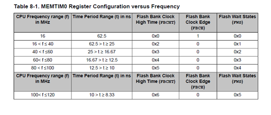
    At 16MHz and above on TM4C129 devices, the wait states are introduced for Flash access. You may be seeing the effects of double fetch cycles because of that.

    Change the System Clock to run at 16MHz or below and the behavior would not be seen.

    Regards

    Amit

  • Hi Amit


    Are you saying to change the clock from 120 Mhz down to 16 Mhz?  I don't see how I can run my whole app at 16 Mhz.


    Also I think this dummy program is running out of SRAM.  Wouldn't that be independent of system clock?

    Thanks again,

    Brian

  • Amit Ashara said:
    At 16MHz and above on TM4C129 devices, the wait states are introduced for Flash access

    Hi Amit,

    Are you quite certain of the "16MHz" value?  Our older, less capable (and less costly) LX4F and basic TM4C usually do not encounter such, "wait-state imposition" until System Clock rises above 40MHz!   Thus the, "more capable, 129" may operate under a (serious) disadvantage...

    Is it not normal that such parts, "improve" w/passage of time and cost increase?  Indeed the 129's peripheral inventory has expanded - but if the 16MHz proves true - there exists a (limited) "System Clock frequency band" (16-40 MHz) in which the older, less costly parts may exceed ithe 129's speed of execution...  (this assumes that > 1 wait state must be introduced when the 129's System Clock is ordered beyond ~80MHz - this fact not yet revealed/expanded - this thread)

  • Hello cb1,

    This has been a part of the data sheet in the Internal Memory Section Table 8-1. I have pasted the same in the post. It may not be as serious disadvantage as the prefetch buffer size has been increased to hold a lot more of the Flash Data.

    Regards

    Amit

  • @Amit,

    Thank you - appreciated.  (this guy - many others)

    "May not be a serious disadvantage" would be better supported by a tightly controlled, "benchmark" comparison - would it not?  (i.e. old/new MCUs running the identical code (where appropriate) at a variety of System Clock settings - then charted - to far more effectively illustrate the impact (if any) of such change upon program execution speed...

  • Hence my interest/concern: http://e2e.ti.com/support/microcontrollers/tiva_arm/f/908/t/299147.aspx

    No further response received from Sue;-(

    Regards,

    Dave

  • Hi Amit,

    I suspect the poster will still experience a 2-cycle pace at lower frequencies as the results from the previous instruction must be written back to RAM before the fetch for the next instruction can be made.  This is why optimizing compilers generally shuffle instructions around to avoid delays due to data dependencies.

    Regards,

    Dave

  • Actually, I must correct myself - the delay is not due to RAM, as the code is only using registers.  The general comment about data dependencies is true, but may no longer apply.

    An interesting test would be to replace the group of sub r2,r1,r1 with a half-length group of interleaved pairs of sub r2,r1,r2 & sub r4,r3,r3.  This would be the same total number of instructions but without possibility of delays for result storing.

    Regards,

    Dave

  • Hello SourceTwo,

    SRAM execution has a one wait cycle which may explain the 2 times execution time. It is however not clear as to is this the only instruction or not?

    Regards

    Amit

  • And these "details" have provided the needed "cover" so that the necessary benchmark issue may be escaped... (sigh)

    (of course - it's duly noted...)

  • Hi Amit


    I looked at the ARM website and this instruction should execute in 1 cycle.  Is the 2-cycle issue that you mention above due to TI's implementation of the ARM Core?

    This is just a dummy program.  I originally wrote a floating point dot product and noticed every instruction executed in 2 cycles.  These were loads (ldr which I would'n be surprised at 2-cycles) vmul.f32, vadd.f32 etc.

    Thanks!

    Brian

  • Hi Dave

    The dummy program executing out of SRAM would have to grab the program line out of the RAM but I don't see any writes back to  RAM.   Even though the program has about 100 lines in the loop I imagine the program would execute out of the  program cache after the 1st loop.

    Thanks,

    brian

  • Hi Brian,

    Time permitting, it may prove "instructive" if you try:

    1000 * 50 of the two-line sequence {sub r1,r1,r2 <NL> sub r3,r3,r4}

    This combination will execute at a 1-cycle pace unless there really is a memory latency issue.  The difference is that the latter sequence does not have an adjacent instruction dependency (no common register).

    If you try this, please let us all know your findings.  I am certain this will run at 1-cycle on the TM4F123 at 80 MHz and I REALLY HOPE it will on the TM4F129 at 120MHz too.  Otherwise, all hope is lost for this family...

    Regards,

    Dave

  • Amit Ashara said:
    It may not be as serious disadvantage as the prefetch buffer size has been increased to

    Presumably the prefetch will be flushed by the function call.

    The presence of the prefetch raises more questions

    • Can it keep up with linear 1 cycle instructions (If it can why is it needed, is it just converting wide memory accesses to narrow)?
    • What is the penalty if the prefetch contents do not contain the next needed instruction?
    • Just how big is it anyway?
    • Does the prefetch do some sort of predictive fetching in the presence of conditional branches?

    Robert

  • Hi Dave

    OK I re-ran the program as you suggested and did not experience any difference.  I ran this at 120 Mhz.  Maybe I should drop the clock speed to 80 Mhz.  In my original post I listed how I set up the timers.  Maybe I made a mistake?

    Tiva TM4C129XNCZAD, 1024-KB flash memory, 256-KB SRAM, 120-MHz operation

    configure timer

       SysCtlClockFreqSet((SYSCTL_XTAL_25MHZ | SYSCTL_OSC_MAIN | SYSCTL_USE_PLL | SYSCTL_CFG_VCO_480), 120000000); 
       SysCtlPeripheralEnable(SYSCTL_PERIPH_TIMER0); 
       TimerConfigure(TIMER0_BASE, TIMER_CFG_PERIODIC); 
       TimerLoadSet(TIMER0_BASE, TIMER_A, 0xFFFFFFFF); 
       TimerEnable(TIMER0_BASE, TIMER_A); 


    read timer

    TimerValueGet(TIMER0_BASE, TIMER_A);

    Thanks again.

  • Might it be "logical" to run at vendor's suggested 16MHz - and see if you can "ever" achieve cyclic improvement? 

    Are we all quite sure the design of the test/monitor (via calls to start timer & then read) is entirely correct/proper?

  • For this sort of test I'd do a pin toggle rather than use the timers.  Just run the test continuously.  It should give you an idea of the jitter as well although I'd be a little surprised if there was enough jitter to measure on something this simple.

    Simple and straightforward.

    Robert

  • Hello Robert,

    1. It is converting wide memory access to narrow

    2. If the prefetch buffer does not contain the next instruction, then it will be flushed

    3. The spec mentions it to be 4 deep 256 wide for the whole flash bank-EVEN and bank-ODD.

    4. No it does not do predictive fetch.

    Regards

    Amit

  • Hi

    I dropped the clock to 16 Mhz and it still comes out at 2-cycles.  I think I must be measuring this incorrectly. 

    At 16 Mhz, program in SRAM, no memory accesses (other than program lines), I'm pretty sure this should run at 1-cycle.

    Thanks,

    brian

  • Hello Brian,

    As I mentioned earlier "SRAM execution has a one wait cycle which may explain the 2 times execution time". Also is the test loop somewhat like the following in Assembly?

    sub r1, r1, r2

    cbz r1, <sub line>

    All,

    If the program is executed from SRAM, then irrespective of the System Clock it is always the same number of wait cycles unlike the Flash.

    Regards

    Amit

  • Hi Amit

    I guess I'm not clear.  I thought SRAM would be faster than flash.  Where does the code execute in single cycle?  cache?

    Here is the code I'm testing with.  I cut this loop down  to 10 instructions.  It measure about 26000 cycles.


        .syntax unified
        .type   Dummy, %function
        .text
        .align  2
        .global Dummy

    Dummy:

       mov r2,#1000
    Loop:

        sub r0,r1,r1
        sub r3,r3,r4
        sub r0,r1,r1
        sub r3,r3,r4
        sub r0,r1,r1
        sub r3,r3,r4
        sub r0,r1,r1
        sub r3,r3,r4
        sub r0,r1,r1
        sub r3,r3,r4

      
        subs r2,r2,#1
        bne Loop

        bx lr

  • Hi,

    Brian,

    I just checked your code - first it is missing an important declaration in .asm: add also .thumb, otherwise is another thing. I run this code, TM4C123GXL, and the number of cycles shown is 13007 for 1000 iterations, 80 MHz.

    Attached is the source file to check (ignore all rubbish,please)

    //*****************************************************************************
    //
    // uart_echo.c - Example for reading data from and writing data to the UART in
    //               an interrupt driven fashion.
    //
    // Copyright (c) 2012-2014 Texas Instruments Incorporated.  All rights reserved.
    // Software License Agreement
    // 
    // Texas Instruments (TI) is supplying this software for use solely and
    // exclusively on TI's microcontroller products. The software is owned by
    // TI and/or its suppliers, and is protected under applicable copyright
    // laws. You may not combine this software with "viral" open-source
    // software in order to form a larger program.
    // 
    // THIS SOFTWARE IS PROVIDED "AS IS" AND WITH ALL FAULTS.
    // NO WARRANTIES, WHETHER EXPRESS, IMPLIED OR STATUTORY, INCLUDING, BUT
    // NOT LIMITED TO, IMPLIED WARRANTIES OF MERCHANTABILITY AND FITNESS FOR
    // A PARTICULAR PURPOSE APPLY TO THIS SOFTWARE. TI SHALL NOT, UNDER ANY
    // CIRCUMSTANCES, BE LIABLE FOR SPECIAL, INCIDENTAL, OR CONSEQUENTIAL
    // DAMAGES, FOR ANY REASON WHATSOEVER.
    // 
    // This is part of revision 2.1.0.12573 of the EK-TM4C123GXL Firmware Package.
    //
    //*****************************************************************************
    
    #include <stdint.h>
    #include <stdbool.h>
    #include "inc/hw_ints.h"
    #include "inc/hw_types.h"
    #include "inc/hw_memmap.h"
    #include "inc/hw_ssi.h"
    #include "driverlib/debug.h"
    #include "driverlib/fpu.h"
    #include "driverlib/gpio.h"
    #include "driverlib/interrupt.h"
    #include "driverlib/pin_map.h"
    #include "driverlib/rom.h"
    #include "driverlib/ssi.h"
    #include "driverlib/sysctl.h"
    #include "driverlib/uart.h"
    //
    #include "inc/hw_nvic.h"          /* for definition of NVIC_DBG_INT */
    #include "inc/hw_memmap.h" /* for definition of DWT_BASE */
    #include "inc/hw_types.h"       /* for definition of HWREG */
    
    #define DWT_O_CYCCNT 0x00000004
    static  uint32_t cstart, cstop;
    volatile uint32_t exe_time;
    
    
    extern void Dummy(void);
    void EnableTiming(void);
    
    //*****************************************************************************
    //
    //! \addtogroup example_list
    //! <h1>UART Echo (uart_echo)</h1>
    //!
    //! This example application utilizes the UART to echo text.  The first UART
    //! (connected to the USB debug virtual serial port on the evaluation board)
    //! will be configured in 115,200 baud, 8-n-1 mode.  All characters received on
    //! the UART are transmitted back to the UART.
    //
    //*****************************************************************************
    
    //*****************************************************************************
    //
    // The error routine that is called if the driver library encounters an error.
    //
    //*****************************************************************************
    #ifdef DEBUG
    void
    __error__(char *pcFilename, uint32_t ui32Line)
    {
    }
    #endif
    
    uint32_t ui32sysclock;
    uint32_t flag;
    uint32_t ssirecv;
    
    void SSI0IntHandler(void)
    {
        static unsigned long ulStatus;
    
        ulStatus = SSIIntStatus(SSI0_BASE, true);
        if (ulStatus == 0x08) flag = 1;
        SysCtlDelay(30);
        SSIIntClear(SSI0_BASE, ulStatus);
        SysCtlDelay(100);
    
    }
    
    void initSSI()
    {
        SysCtlPeripheralEnable(SYSCTL_PERIPH_SSI0);
    
        SysCtlPeripheralEnable(SYSCTL_PERIPH_GPIOA);
        GPIOPinConfigure(GPIO_PA2_SSI0CLK);
        GPIOPinConfigure(GPIO_PA3_SSI0FSS);
        GPIOPinConfigure(GPIO_PA4_SSI0RX);
        GPIOPinConfigure(GPIO_PA5_SSI0TX);
    
        GPIOPinTypeSSI(GPIO_PORTA_BASE, GPIO_PIN_2|GPIO_PIN_3|GPIO_PIN_4|GPIO_PIN_5);
    
        SSIConfigSetExpClk(SSI0_BASE, SysCtlClockGet(), SSI_FRF_MOTO_MODE_3, SSI_MODE_MASTER, SysCtlClockGet()/8, 8);
    
        HWREG(SSI0_BASE + SSI_O_CR1) = 0x00000010; //EOT = 1
        SSIEnable(SSI0_BASE);
    
        IntEnable(INT_SSI0);
        SSIIntEnable(SSI0_BASE, SSI_TXFF); //  | SSI_RXFF | SSI_RXTO | SSI_RXOR
    
    }
    
    int main(void)
    {
        FPULazyStackingEnable();
        SysCtlClockSet(SYSCTL_SYSDIV_20 | SYSCTL_USE_PLL | SYSCTL_XTAL_16MHZ | SYSCTL_OSC_MAIN); //10 MHz
        ui32sysclock = SysCtlClockGet();
        initSSI();
        EnableTiming();
        IntMasterEnable();
    
        while(1){
    
        	for(int i = 0; i < 4; i++){
            SSIDataPutNonBlocking(SSI0_BASE, 0xF0);
            SSIDataGetNonBlocking(SSI0_BASE, &ssirecv);
           }
           SysCtlDelay(10000);
           // timing measurement
           cstart = HWREG(DWT_BASE + DWT_O_CYCCNT);
           Dummy();
           cstop = HWREG(DWT_BASE + DWT_O_CYCCNT);
           exe_time = cstop - cstart;
        } //  set here a breakpoint
    }
    
    void EnableTiming(void){
    static int enabled = 0;
    
    if (!enabled){
       HWREG(NVIC_DBG_INT) |= 0x01000000;  /*enable TRCENA bit in NVIC_DBG_INT*/
       HWREG(DWT_BASE + DWT_O_CYCCNT) = 0; /* reset the counter */
       HWREG(DWT_BASE) |= 0x01;            /* enable the counter */
       enabled = 1;
     }
    }


    Petrei

  • If it is like the 123 there is a prefetch buffer on flash only.  So executing from RAM will run without the prefetch buffer for good and for ill.

    The prefetch buffer on the 123 series does recognize branches and stops fetching allowing for the possibility of a backwards branch staying in the buffer so it has some cache like behaviour.  Amit's description suggests the 129 does not do this but I suspect it does.  This does only apply to flash though. 

    Note that in flash your bne at the bottom of the loop could result in a wait as the prefetch buffer's first entry is read (loading the first instruction again) if the loop does not fit into the prefetch or if branches unconditionally flush the prefetch queue.


    Robert

  • Petrei

    According to a post by Amit the SRAM on the 129 takes a wait state.  Did you run this code on the 123 out of Flash or SRAM?  Does the SRAM have the same penalty as it does on the 129?

    I will try using your .c file to make the measurements.

    Thanks,

    Brian

  • Hi,

    On 123 I am running on flash. I will try also on a 129, also from flash, I am curious...

    Petrei

  • Hi Petri,

    Your cycle count on the '123 is as expected - I am waiting with bated breath to see if the '129 does as well.  I really hope so,as future plans need more performance (much greater than 120MHz would be nice) and I sure don't want to port code to another vendor;-(

    Thank you for checking this on the '129!

    Regards,

    Dave

  • Hi,

    I have checked today also on TM4C129 - the result was almost the same - 13012 cycles.

    Please run the same to check/verify before jumping to possible wrong conclusions.

    Petrei

  • Thank you!

    I am grateful for the first '129 performance data that I have seen.

    Regards,

    Dave

  • Hi Petrei/Dave/Amit/cb_1

    Thank you very much to all for your help. I too confirm that I get single cycle when running out of Flash at 120 Mhz on the 129.   As mostly being a DSPer, I'm a little surprised/baffled that I can get better performance from the flash than I can get out of the SRAM.   In all sincerity, if someone knows what advantages the SRAM brings, I'd be interested to hear what it is so I will know how to leverage it in the future.

    Thanks Again!

  • Hi,

    Brian, since you are interested, I attach below a document from ARM describing DSP capabilities of Cortex-M4.

    8662.Developing_Advanced_Signal_Processing_Software_on_the_Cortex-M4_Processor.pdf

    Enjoy! (and please mark this thread as answered).

    Petrei

  • Thank you again.

  • Hello Brian

    The Flash for a small loop code would be reading from the prefetch buffer giving the single cycle latency, but when running a larger code it may cause prefetch flush and fill too often. On the SRAM this would be always a two clock cycle latency irrespective of the system clock frequency.

    Regards

    Amit

  • Hi Amit/Brian,

    Amit - I am surprised by the claim of a two-cycle latency on the SRAM, both because it would be unique to the '129 and because the data sheet claims "256 KB single-cycle System SRAM".  Every M3 & M4 I have looked at from every vendor has single-cycle (no-wait-state) SRAM.  In Brian's case, with no data read/write occurring to SRAM, I would have expected the best possible performance.  The only explanation that makes sense to me is that the SRAM may not have the best bus-connection (i-fetch optimized) to the core?

    Brian - when you successfully obtained the 130xx-cycle count out of flash, were you using the same code sequence you tried earlier from SRAM?  Is your SRAM vs. Flash measurement apples-to-apples?

    Amit - Please note that "8.2.5 Bus Matrix Memory Accesses" in the data sheet indicates that the CPU Data Bus cannot access SRAM - certainly a documentation error...

    Regards,

    Dave

  • Hi Dave

    Yes, exactly the same code.

    Thanks!

    brian