This thread has been locked.

If you have a related question, please click the "Ask a related question" button in the top right corner. The newly created question will be automatically linked to this question.

16x2 LCD interfacing with Stellaris LaunchPad


I am using the Stellaris launchpad. I am trying to connect my Stellaris Launchpad with my LCD. I want to interface with my LCD by using 8-Bit Data interfacing. I am having trouble doing that. I have chosen PORTE and PORTB to connect to the LCD data pins. I connected PE5 to the Register Select  Pin (RS) and PE3 to the Enable Pin (E), and PE4 as my R/W pin.  Below you will find my pin connections from the Stellaris Launchpad to the LCD.

Stellaris Launchpad Pin PB0 PB1 PB2 PB3 PB4 PB5 PB6 PB7
LCD Pins 7 (D0) 8 (D1) 9 (D2) 10 (D3) 11 (D4) 12 (D5) 13 (D6) 14 (D7)

below is my code which i have written using direct register write.


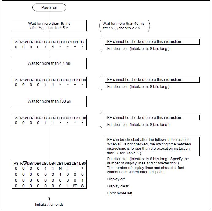
but its not working, when i power the lcd only the 1st row displays the black boxes and after flashing the code nothing happens.

any pointers???

  • i dont think their is anything wrong with my code, i have not used a POT, i connected the VEE pin to ground which gives full contrast like black boxes in the 1st row and nothing in the 2nd row, is that all right??

  • ok i have installed a POT and its just varying the brightness of the black boxes in the 1st row. when i flash the code nothing happens.

    i have also read the entire thread you mentioned , but it doesnt solve the problem.

    here is my code:


    /*Author: TAIMUR ADNAN
    	
    ---------------Pin Map--------------------------------
    VSS-GND                                               |
                                                          |
    VDD-VCC                                               |
                                                          |
    VEE-GND(for contrast, but we dont have the Pot)       |
                                                          |
    DB7------PB7                                          |
    DB6------PB6                                          | 
    DB5------PB5                                          |
    DB4------PB4                                          |
    DB3------PB3                                          |
    DB2------PB2                                          |
    DB1------PB1                                          |
    DB0------PB0                                          |
    																											|
    R/W------PE4                                          |
    RS-------PE5                                          |
    E--------PE3                                          |
                                                          |
    LED+-----3.3V                                         |
    LED- ----GND                                          |
                                                          |
     -----------------------------------------------------
    */
    
    #include "lm4f120h5qr.h"


    void Lcd_INIT_ritual(void);
    void delay(unsigned long value);
    void cmd_write(void);
    
    void check_busy(void);
    
    void E_Trigger_R(void);
    void E_Trigger_W(void);
    
    void lcd_CMD_Write(char cmd);
    
    void data_write(void);
    
    void delay(unsigned long value){
    		int i = 0;
    		int j=0;
    		for(i=0;i<value;i++)
    		{
    			for(j=0;j<value;j++);
    		}
    	}
    
    	void lcd_DATA_Write(char data);
    
    	unsigned long delay2;
    	void Lcd_INIT_ritual()
    	{
    		
    		SYSCTL_RCGC2_R |= 0x12;           // Port E and B clock
                    delay2 = SYSCTL_RCGC2_R;           // wait 3-5 bus cycles
    		
    		
    	        GPIO_PORTE_DIR_R |= (1<<3)|(1<<4)|(1<<5);   
                    GPIO_PORTB_DIR_R|= 0x0FF; // portB
    	
    	        GPIO_PORTB_AFSEL_R &= ~0x0FF;      // not alternative
                   //GPIO_PORTB_AMSEL_R &= ~0xFFFFFFFF;      // no analog
                     GPIO_PORTE_AFSEL_R &= ~0x0FF;      // not alternative


    	        GPIO_PORTE_DEN_R |=(1<<3)|(1<<4)|(1<<5); 
    	        GPIO_PORTB_DEN_R |= 0x0FF;
    		
    		// GPIOE_ODR: output data register
    		delay(500);
    		//cmd_write();
    		//GPIO_PORTE_DATA_R|= (1<<3); //Enable=1
    		
    		lcd_CMD_Write(0x38);
    		delay(800);
    		
    		lcd_CMD_Write(0x0E); //display on, cursor blink
    		delay(800);
    		
    		lcd_CMD_Write(0x06); // increment on, shift off
    		delay(800);
    		
    		//lcd_CMD_Write(0x0C); // display on ,rest off
    		delay(800);
    		
    		//lcd_CMD_Write(0x28);// 2 lines, font 5x8 4 bit mode
    		lcd_CMD_Write(0x01);// clear screen
    		delay(800);
    	}
    	
    	void lcd_CMD_Write(char cmd)
    	{
    		//check_busy();
    		delay(200);
    		cmd_write();
    		
    		GPIO_PORTB_DATA_R=(GPIO_PORTB_DATA_R&0xFFFFFF00)|cmd;
    		E_Trigger_W();


    	}


    void lcd_DATA_Write(char data)
    {
    					check_busy();
    					data_write();
    					
    					GPIO_PORTB_DATA_R=(GPIO_PORTB_DATA_R&0xFFFFFF00)|data;
    					E_Trigger_W();
    
    
    }
    
    	
    	void cmd_write()
    	{
    		GPIO_PORTE_DATA_R &=~(1<<4)|(1<<5);  // R/W=0, RS=0;
    	
    	}
    	
    	void E_Trigger_W()
    	{
    			GPIO_PORTE_DATA_R|=(1<<3);
    			delay(200);
    			
    			GPIO_PORTE_DATA_R &=~(1<<3); // to produce a falling edge
    	}
    	
    	void E_Trigger_R()
    	{
    		
    		GPIO_PORTE_DATA_R&=~(1<<3); // to produce a rising edge
    		delay(200);
    		GPIO_PORTE_DATA_R|=(1<<3);
    	}
    	
    	void check_busy()
    	{
    		GPIO_PORTB_DIR_R&=~(1<<7); // make DB7/PE3 input for busy flag
    		while((GPIO_PORTB_DIR_R&(1<<7))==(1<<7)) //read PE3/DB7
    		{
    				E_Trigger_R();
    		}
    		
    		GPIO_PORTB_DIR_R|= (1<<7);// make back OUTPUT
    		
    	}
    	
    	void data_write()
    	{
    		GPIO_PORTE_DATA_R|=(1<<5); //RS=1
    		GPIO_PORTE_DATA_R&=~(1<<4);//R/W=0 
    	
    	}
    	
    	
    	int main()
    	{
    		Lcd_INIT_ritual();
    		delay(600);
    		while(1)
    		{
    			lcd_CMD_Write(0x01);
    			delay(1000);
    			lcd_CMD_Write(0x81);
    			delay(1000);
    			
    	        	lcd_DATA_Write('H');
    	 
    		}


    }
    	
    
    i have spend 4 days on it but to no avail.
    	

  • Hello ad,

    Is it the same panel as what is there in the link post that Kel mentioned

    Regards

    Amit

  • i have a 16x2 LCD Model: JH162A it has green backlight, if that is what you are asking

  • Proper initialization is mandatory for such displays - double check.  Your report of top character row being darker is the normal/default mode of such Lcd controllers.  The fact that it does not transition to, "each row being equal in contrast" signals that your initialization into 2 row mode has failed!

    We note that you use simple, delay constructs to achieve the "very demanded" Lcd timing.  If you have your IDE set for anything beyond low (or no) "optimizations" - such delay may be "eaten" by the compiler.

    A scope to confirm the width and clean edges of "E" is a great test method...

    As always - your use of direct register (rather than the heralded vendor library) greatly complicates debug assistance by this vendor and "outsiders" (i.e. this reporter)  As a form of protest - I avoid such posts as it eats too much time/effort - and shows less than, "Stellar" concern for your helpers...

  • Sir cb1,

    first of all, thank you so much for replying to me, i appreciate your time.
    secondly, i have changed my configurations to that of the threads configuration u gave.

    Stellaris Launchpad      PB0   PB1   PB2     PB3        PB4   PB5   PB6         PB7      PA6   PA7

    LCD Pins                    7(D0)  8(D1) 9(D2)  10(D3) 11(D4) 12(D5) 13(D6) 14(D7)   4(RS)   6(E) 

    i have flashed the exact code given in the the thread, the one on the 2nd page, (Mahmouds code).

    it complies perfectly, i.e with 0 errors. and i also debug it, and watch the GPIO peripherals--> they change just fine.

    but nothing happens on the LCD display... just the same black 1st row.

    those delay time which i had used in my code work fine with LED,s 

    and no.....i dont have an oscilloscope or a logic analyzer to test the E pin.

    i have used the direct method because being a student our teacher prohibits the use of library, and encourages us to read from the datasheet and write the code. i know this method is time consuming but we get to learn alot.

    i have commented my code as much as i could, if you want me to further comment it, please tell me so that i wont eat your time/effort to understand it.
     

  • ad AD said:
    Sir cb1,

    Long ago - in the Army - such title was proper - but surely not now - not here.

    Longer delays between each/every code step w/in Lcd Init - rather than shorter - always best.  As past stated - the fact that your lcd retains, "dark top row, light 2nd row" always indicates that your initialization (into 2 row mode) has failed!

    Failed init stems from:

    a) improper init code

    b) improper init sequence

    c) violation of (strict) init timing requirments

    d) failure to drive RS=RW low prior to assertion of E strobe

    e) E strobe noisy, too short or otherwise deficient

    f) misconnection between MCU & Lcd's DBus or short/open etc.

    If you wish - save me the time/effort of digging into direct register - simply list here the init code sequence you intended.  Don't need any code - just the code values and their sequence - and what you believe the proper delays between each/every sequence was to be.

    What your teacher may not (fully) appreciate is that industry cannot "allow" such slowed, inefficient "learning" - our doors could not remain open - investors would not, "pile yet more cash" if "learning overtakes product shipment!"  Your school is not alone in that - one wonders if your "learning" - via assistance from others, here - will still work when school is out/over - and a boss may growl when forum response is too slow...

    Long ago we could only write code in assembler - and 10 lines per day was ok.  But - only in the most rare - most time-critical cases - would we even consider such use today!  Does not teacher's suggestion/rule make you less competent/capable w/vendor's superb driver library - and thus less employable?  (something, perhaps to consider...)

  • here is my initialization sequence:

                    lcd_CMD_Write(0x38);
    		SysCtlDelay(12500);
    		
    		lcd_CMD_Write(0x0E); //display on, cursor blink
    		SysCtlDelay(12500);
    		
    		lcd_CMD_Write(0x06); // increment on, shift off
    		SysCtlDelay(12500);
    		
    		lcd_CMD_Write(0x01);// clear screen
    		SysCtlDelay(12500);
    
                   
    		lcd_CMD_Write(0x80); 	// starting address of the 1st block		     
                    SysCtlDelay(12500); // 1 ms delay using 12.5MHZ clock(200M/16)
    

  • HI,

    Sorry to say, these are your intentions, not the real code (as posted the fist time). There you use a delay routine with one nested loop into another one, so the real time spent (for instance when you pass "800" as parameter) is 800*800*3 clock cycles, since each C line in loop is executed in 3 .asm instructions (at least, depends..) - this is somewhere around 460ms instead only one. As cb1 said, do check again, follow his advice.

    Another source of info is this if you need to use direct method - look for LCD_1968.zip package - can be easily transformed for your micro.

    Petrei

  • Friend Petrei (as always) makes good points & provides a link. (although I don't believe that simple, "copy/paste" ever meets or even approaches the proper goal of, "education/learning.")

    Let's look at your init. - 4 commands - but last one is nonsensical as 0x01 (CLS) earlier clears the Lcd & homes cursor - thus the final 0x80 serves no purpose - telegraphs confusion/ineptness.  Thus the "source" of this code becomes highly suspect. (and - it's likely that you've adopted yet more - from this (perhaps) questionable source)

    As public service - here's a scan from, "Horse's mouth" HD44780 ADE-207-272(Z)'99.9 Rev.0.0 - listing "their" 8-bit initialization sequence:

    Now others here have past posted - and the net is awash with, "singular reports of text Lcd success" - but are not all such reports really - just, "anecdotal?"  (i.e. they worked "once" w/some unknown/undescribed clone Lcd control IC)  Is that good - is that real science?  Thus I present the sequence above - from the, "father" of all subsequent text lcd ICs.

    Earlier, before eys crossed and watered (in the attempt to review the always delightful (and unneeded) direct register code) I noted reference to, "Busy."  Should you/others, "get that wrong" (often happens) each/every LINE of your code following such, "Busy Read" attempt may, "Never/ever be executed!"  Note again my public service (above) which alerts that BF (busy flag) cannot be ("successfully" - credit cb1) checked until, "3 successful writes of 0x3x" have landed!  Now I've cofounded - took past display firm public - and many times have "reduced that (3) number."  But such reduction is not guaranteed to always work - and w/some Lcds - some controllers - will (and does) FAIL!  Your code of course employs just ONE 0x3x - I trust my past, "in the biz" great experience & Hitachi data over any, "unknown, 3rd party, anecdotal, one-time (reported) display success!"

    Thus - your investigatory skills need tweaking.  Borrowing/stealing existing code (which we know to be always perfect!) is quick/easy - but at what cost?  Would not your search for, "the original" be more secure?  Did the teacher - surely interested in education & learning - sound this alarm?  Might the focus on the complexity brought on by, "direct register" have caused very predictable, "collateral damage?"  (i.e. no time/strength to properly investigate critical source data...)

    At this stage - diagnosing your issue - w/out your use of scope & confirming signal widths, delays, timings: is remarkably similar to, "Guiding a blind man - with a bad leg - through a minefield."  (gf & I perform such service - alternate Tuesdays)

    Writing 3 times, "0x3x" with even excessive time delays (as above) - cannot hurt!  At minimum brings you into compliance.

    Among the largest code errors with such text Lcds is the "common toggling" of RS/RW & E.  This results in the sure violation of RS/RW "set-up" time prior to the E signal going high.  (same data sheet (above) details)  This is done because "unskilled/unknowing" (equally bad - my book) code writers "SAVE" an instruction by "bundling RS/RW & E!"  This is most likely to land/intrude upon the change from an Lcd Command to Lcd Data.  (when RS toggles low to high)

    The abandoned KISS cries out in protest...  All hale "direct register" - but not at the expense of all "necessary" others...

  • Hi,

    @cb1-,

    I agree with you - copy paste is never good - but at least that example could be a good source to see how others have solved some problems, i.e. timing - there is an interesting routine for that. And with copy/paste but without good and full understanding of what's in there is useless. At least the poster can/should compare the event succession in both  implementations (his and the example) and correct his code. That's my intentions, anyway.

    Petrei

  • Hi Petrei,

    Please understand - your efforts here are great - always appreciated.  And - just as you later, "detailed" you were not suggesting, "blind cut n paste!"  I wanted to "drive home" that point - which your follow on writing did.

    I'm on the water now - net is "in/out" - I had to compose & dump 5,6 times to get that post up.  (plz give a read, again - if you've time)

    The focus on direct register - to my mind - caused "nearly all else" to be short-changed.  That can't be good for "in the biz" guys like you/me - if we miss a critical fact - we're in "big trouble!"  Yet - school's "too singular focus" - in my mind - guarantees just that! 

  • Hi Petrei,

    Thanks a lot for the Link, it was of great help, i have done a lot of tweaking to my code, stripped of that "cheap delay" routine and used Systick timer. i 1st tested the timer on LEds, using 16Mhz clock to provide 5, 10 s delay for the blink. and it worked as expected. then using that timer i provided accurate delays.

    here is my new Initialization sequence :

    void Lcd_INIT_ritual()
    	{
    		GPIO_PORTE_DATA_R=0; // E=0, R/W=0, RS=0
    		SysTick_Wait(256000);// 16m sec delay 
    		lcd_CMD_Write(0x30);
    		SysTick_Wait10ms(1); //10ms delay
    		
    		lcd_CMD_Write(0x30);
    		SysTick_Wait(8000); // 500us sec delay
    		
    		lcd_CMD_Write(0x30);
    		SysTick_Wait(8000); // 500us sec delay
    		
    		/*lcd_CMD_Write(0x02);
    		SysTick_Wait(8000); // 500us sec delay
    		*/
    		lcd_CMD_Write(0x38);
    		lcd_CMD_Write(0x10);
    		lcd_CMD_Write(0x0C); //display on, cursor blink
    		lcd_CMD_Write(0x06); // increment on, shift off
    	
    	}

    i realized that 2 (pseudo) initialization sequences are required, and the (0x30) first one was sort of missing.

    also here is the "lcd_CMD_Write " Function with appropriate delays:

    	void lcd_CMD_Write(char cmd)
    	{
    		GPIO_PORTB_DATA_R= cmd;
    		cmd_write(); // makes RS,R/w and E=0, and includes a 6us delay
    		E_Trigger_W(); // includes the 40us delay
    			
    	
    	}

    and the "E_Trigger_W()" :

    void E_Trigger_W()
    	{
    			GPIO_PORTE_DATA_R|=(1<<3);//E=1
    			SysTick_Wait(96); // 6us
    			
    			GPIO_PORTE_DATA_R &=~(1<<3); // E=0   to produce a falling edge
    			SysTick_Wait(640); // 40us mandatory delay for the command to execute
    	}

    and in the main function after initialization i.e in the while loop i have used ''LCD Clear"' the same way as it was used in the link you gave me:

    while(1)
    		{
    			LCD_Clear();
    			lcd_DATA_Write('T');
    			SysTick_Wait10ms(100);
    		}

    but still it wont work:( , this is turning out to be very frustrating. 


  • Hi,

    OK, good, make now some debugging: set some breakpoints inside some commands - for instance inside E_Trigger_W, after Systick_wait and verify with multimeter the status of pins E, RS, RW - i am sure you will find out the bug. Check each signal and see what is wrong/missing. Do not forget to adjust the voltage at pin 3.

    See also the debugging method shown by cb1.

    Petrei

  • Latest/greatest code posted fails to show:

    Lcd DATA Write code segment

    and

    LCD_Clear code segment

    Immediately upon the Lcd controller's (successful) receipt of "0x38" the top row's contrast should decrease and the bottom row's contrast should increase (bringing that row into equal prominence.)  Should that, "notable shift in contrast" not occur - all following attempts are likely (bound really) to fail.

    Two (alleged - confirmed not by scope but by anecdotal, past Led test!) 40uS delays appear.  But - after CLS (0x01) a delay of ~2mS is normal/customary/MANDATED!  If that's not properly implemented - your while loop will fail as the write of "T" occurs far too soon.   And - after the write of "T" heralded 10mS delay arrives - that may be for ease of screen read but fails in meeting CLS requirement...

    To my mind - for reasons listed - code thus shown is not, "best/brightest."

    If hand wired rather than ID (insulation displacement) ribbon cable connected - adjacent pin short is always a possibility. 

    By the way - where's the, "teacher?"

  • void lcd_DATA_Write(char data)
    {
       GPIO_PORTB_DATA_R=data;
       GPIO_PORTE_DATA_R|=(1<<5);           //RS=1
       GPIO_PORTE_DATA_R&=~((1<<4)|(1<<3)); //R/W=0, E=0 
       SysTick_Wait(96); // 6us
    
       GPIO_PORTE_DATA_R|=(1<<3);//E=1
       SysTick_Wait(96); // 6us
    			
       GPIO_PORTE_DATA_R &=~(1<<3); // E=0   to produce a falling edge
       SysTick_Wait(640); // 40us mandatory delay for the command to execute
    
    
    }

    void LCD_Clear(void)
    		{
    			lcd_CMD_Write(0x01); // Clear Display
    			SysTick_Wait(25600); // wait 1.6ms
    			lcd_CMD_Write(0x02);  // Cursor to home
    			SysTick_Wait(25600); // wait 1.6ms (as given in the datasheet)
                    }


    i didnt post the complete code beacause you said not to do so. 
    my teacher is on  vacation, and is not returning any time soon. so no contact- email etc.

  • Trying to assist you (as I do w/staff here, our firm) I twice gave you the "hint" observe Lcd's contrast "change" just after the write of 0x38.  Yet - no return response from you - shouldn't you provide that data?  (you may need to read "helpers'" posts several times - even print - and underline/highlight each/every request.)  Note: I do just that w/each/every client order and request - it is seen as, "disrespectful" to omit such care/concern!  (word to the wise - one hopes...)

    Note another "missed" earlier comment.  Your clear "homes" the cursor twice!  (that makes sense!)  0x01 clears the screen AND homes the cursor!

    Your SysTick_Wait values signal that your system clock is 16MHz - is that the case? 

    If you can't beg/borrow/steal a pot - can you find close to 1K & 10K resistors?  Create a voltage divider - tie the junction to pin 3 (Vo) smaller R to ground, remaining R to +5V.  You've not mentioned if the Lcd is powered by 5V - is that true?

    Suggest that you focus upon just Initialization - composed solely of Lcd Command Writes - let's get the contrast between each row to equalize - that proves that - at minimum - your data bus, RS,RW and E strobe have some correctness.  (no need for Lcd Data Write at this time)

    To that end keep all 3 0x38 writes - but lenghten each delay by factor of ten!  (failed delay will waste more time/energy - again we're minefield walkers - due to awol scope)  After the 3rd 0x38 - comply w/longer delays and use 0x06, 0x0E, 0x01.  Note: all six of these are Lcd Commands - NOT Lcd Data!   When code's correct - and survives transport across your (we sense) jumble of wires and well-checked/tested/verified solder joints (we surely hope!) - the display's contrast will notably change upon the receipt of that 3rd 0x38!

    If you've not exhaustively ohmed-out each every connection between MCU and Lcd - that really must be done.  You waste Petrei's/my/others' time by avoiding that effort - really unfair/wasteful - karma killing...

    Note that I'm also "on vacation" yet unlike school "other" -  contact/effort continues...  (says something - mais non?)

  • i did as you mentioned inc delay by 10 times, and did 3x(0x38) but i didnt observe any change in contrast.

    yes the clock is 16Mhz, and my supply is coming from micro VBUS which is 5V and i have debugged my connections thoroughly, each and every pin, then debugged each code line, so  for example when i write 0x30 which is 0b00110000 which corresponds to PB4 and PB5  i observe voltage(multimeter) at these 2 pins and 0v at the rest(PB0..PB7). i also debugged the latch/strobe/trigger pin aka E pin aka PE3 which goes high when its 1 and low voltage on multimeter when its made 0, so proper deflection is observed in the debugging mode.

    MY CONNECTIONS:

    i have used a 16pin ribbon cable to connect it to my micro, along with jumpers and breadboard. demoralized by this connection i stripped off, and made new connections from scratch , and in the process i think i shorted the LED+ LED- pin.  now when i power up my LCD  with VEE(contrast pin) to ground its no longer giving COMPLETE dark 1st row.:

    and this is without the PB port pins, just LED+,LED- and (GND)VSS,VCC,and VEE. 

    is my display ruined??

  • Ouch - that's not good news!  And - great job by you in providing detailed answers to (what my experience has taught) necessary, diagnostic questions.  (Diagnostics is a large part of my firm's biz)

    When you speak to Led+ & Led- I believe those are reserved for the Led backlight - and (usually) those signals will not impact the Lcd proper.  You must "current limit" the 5V you supply to the Led backlight - hope you've done that.

    Might that "short" have damaged your supply?  Have you measured the voltage @ the 14 pin Lcd connector - insuring that 5V and ground and (near) ground appear at Vo - after the short?  You've not answered as to yours being a 5V or 3V3 display!

    I did not mean for you to tear apart the ribbon cable & headers (ideally one @ Lcd - 2nd @ MCU board).  That's preferred as the best - most robust means to display success.  Also - allows the quick replacement or substitution of the display.

    Thanks for detailing your connections and verifying their correctness.  Be aware - you should assume, "nothing!"  In electronics - unlike so many (all?) other fields - we are "bums" when 99.9% correct.  So - as we sometimes read here, "Devil is in the (very) necessary detail!"  And - as you progress - experience will help but you must always keep this awareness.  (just ask friend Petrei - sure he'll agree)  Engineering/Programming is not for everyone - don't say to discourage - just alert...

    That loss of "darker top row" may not be all bad - we've seen such displays come up "quiet" when critical pins float.  (it's not hard to imagine that random noise upon "E" has clocked in "krazed" data.

    Remake your connections - try again (with long init delays) and just allow the code to run to INIT completes - no further!  That would be KISS.  We're looking for the contrast to change from top row only to top-bottom row BALANCE!  That confirms that the display has received valid, 2 line init. 

    Cannot hurt to acquire 2nd, 3rd display - accidents happen & we have no proof that your display was ever good!  (I blame the school - with current facts in evidence)

    As a general troubleshooting tip - by latching the Data Bus first with 0x55 - and then with 0xCC.  Such drives first all even numbered bits high and then all odd numbered bits high.  This eases your test of the D. Bus for adjacent pin shorts/opens.  (firms such as ours have a "million" of these tips/tricks...)  (million? - maybe not)

    I'd really try for 2nd display (ideally known good).  This level HW troubleshooting should not be forced upon you - nor upon Petrei/myself - who have been drawn in and seek only to assist.  (that teacher...not so much)

  • POWER SUPPLY:

    the power comes from my laptop via usb cable connected to the micro, the uC has 2 power options 3.3v/5v, i have used 3.3v to power the LED+ /LED- pins. using 5V only makes it a bit brighter, so i settled for 3.3v, and no i didnot use any current limiting . the LCD Voltage/VCC is definitely 5v tolerant:

    its states here it can handle upto 11V.

    i also tested the Vo/VEE/contrast pin which is actually attached  to ground, measuered the voltage between the 3.3and/5v and this VEE pin, it worked just fine as i was getting proper deflections(i tested using both voltages).

    i earlier used a slider pot to vary the contrast and it was varying but since i want to keep it to max i set it(VEE) to ground.

    i tried that 0x55 and 0xCC and they work just fine, for instance i was getting alternate deflections with 0x55 which show that the display is receiving data but not showing the effect...

    i also tried using long delays with the int code, a change in contrast by 0x38 will be a sight for sore eyes now!!..which has not yet happened!

    i am trying to contact the lab Attendant who sold me the LCD, still hasent heard from him,so it seems its unlikely he will reply. getting a 2nd display is a big hassle/ but i guess its the only way out now.
     
    i think i will try 4-bit mode now......should i? 

  • Hi,

    I think you got too much inspiration from the Valvano's example, which is 1 row x 8 characters - so please modify your code for two rows x 16 characters - you may post the code also, but as a file.

    Petrei

  • ad AD said:
    i think i will try 4-bit mode now......should i? 

    How to answer - we can't launch our rocket successfully to the moon - so - let's try for Mars!  Do you really believe that adding complexity - while instructors/lab assistants "hide" - makes sense?  The only way that could conceivably help is if there was damage to one or more of the lower order D bus.  (D3-D0)  But - I've quite deliberately asked you to confine your tests to Display INIT - which cares not one whit - about those lower 4 bits!  Desperation is not adequate justification for, lack of proper thought/planning."

    That display spec stinks.  It lists Vdd as acceptable over a very wide range - yet lists the "Lcd Voltage (Vo)" as constant - independent of that range - which cannot be. 

    You're imprecise in your report (several times) - you state, "measured the voltage between 3V3/5V and this (Vee) pin - worked just fine!"  Thank you very much - tells we helpers very little.  A real voltage reading lets those w/perhaps - bit more experience - judge, "what is fine."  Be aware - better you hear this from me here than, "on the job!"  Again & again - engineering problems revolve around, "Detail."  Fine ain't detail!  Ok?

    You go on - (reporting upon 0x55 & oxCC results) state you were getting, "alternate deflections" - which show the display is receiving data.   May I ask, "How you draw that conclusion?"  Is it not more likely that your MCU DBus signals "successfully reached" to your DMM probe point?  How do you know they made it the final added mm to the HD44780 (or clone) IC?

    None of this intends to, "beat you up."  Instead - attempts to display the, "clarity of logic/thought" forced upon those who venture into this field.  If we accept, "bad/incomplete" data while performing diagnostics - we EAT time/money - likely demoralize staff & client.  And that ain't good.

    With respect to Lcd's Pin 1 (Vss) I'd like your recent (today) measure of Vdd(pin 2), Vo(pin 3), RS(pin 4), RW(pin 5) and E(pin 6) - those last 3 with the pins ordered "fixed" high by the MCU.  Ideally I'd like RS, RW, E to go high only one at a time - not in unison!  And - as you measure the targeted pin - measure all others in this grouping in that measurement process.  (I'm seeking an RS-RW-E "short")

    And - you now have gone "silent" as to the recent report of, "loss of contrast" after your Led +/- short.  Has the upper line - high contrast condition restored?  If so, how?  We are using the disparity in contrast between top/bottom rows as a critical diagnostic tool - all is lost if neither row is visible...

    Are you in USA?  (if so I'll ship you a display we've test/verified)   (note: like teacher/assistant - I'm on vacation...)

  • @Petrei
    i am sorry i dont understand? 0x38 stands for 8-bit 2 line 5x7 style. i checked valvanos code and in the intial comment section he says size 1 *8...

    "

    8 characters are configured as 1 rows of 8
    addr 00 01 02 03 04 05 06 07

    "
    does me mean custom characters? like using CGRAM?
    please elaborate?

    /*Author: TAIMUR ADNAN
    	
    ---------------Pin Map--------------------------------
    VSS-GND                                               |
                                                          |
    VDD-VCC                                               |
                                                          |
    VEE-GND(for contrast, but we dont have the Pot)       |
                                                          |
    DB7------PB7                                          |
    DB6------PB6                                          | 
    DB5------PB5                                          |
    DB4------PB4                                          |
    DB3------PB3                                          |
    DB2------PB2                                          |
    DB1------PB1                                          |
    DB0------PB0                                          |
    																											|
    R/W------PE4                                          |
    RS-------PE5                                          |
    E--------PE3                                          |
                                                          |
    LED+-----3.3V                                         |
    LED- ----GND                                          |
                                                          |
     -----------------------------------------------------
    */
    
    #include "lm4f120h5qr.h"
    #include "inc/hw_types.h"
    #include "inc/hw_memmap.h"
    #include "driverlib/sysctl.h"
    #include "driverlib/gpio.h"
    #include "stdio.h"
    
    void SysTick_Init(void){
      NVIC_ST_CTRL_R = 0;                   // disable SysTick during setup
      NVIC_ST_RELOAD_R = NVIC_ST_RELOAD_M;  // maximum reload value
      NVIC_ST_CURRENT_R = 0;                // any write to current clears it
                                            // enable SysTick with core clock
      NVIC_ST_CTRL_R = NVIC_ST_CTRL_ENABLE+NVIC_ST_CTRL_CLK_SRC;
    }
    // Time delay using busy wait.
    // The delay parameter is in units of the 50 MHz core clock. (20 nsec)
    void SysTick_Wait(unsigned long delay){
      volatile unsigned long elapsedTime;
      unsigned long startTime = NVIC_ST_CURRENT_R;
      do{
        elapsedTime = (startTime-NVIC_ST_CURRENT_R)&0x00FFFFFF;
      }
      while(elapsedTime <= delay);
    }
    // Time delay using busy wait.
    // 10000us equals 10ms
    void SysTick_Wait10ms(unsigned long delay){
      unsigned long i;
      for(i=0; i<delay; i++){
        SysTick_Wait(160000);  // wait 10ms (assumes 16 MHz clock)
      }
    }
    
    
    void Lcd_INIT_ritual(void);
    void delay(unsigned long value);
    void cmd_write(void);
    
    void check_busy(void);
    
    void E_Trigger_R(void);
    void E_Trigger_W(void);
    
    void lcd_CMD_Write(char cmd);
    
    void data_write(void);
    
    void delay(unsigned long value){
    		int i = 0;
    		int j=0;
    		for(i=0;i<value;i++)
    		{
    			for(j=0;j<value;j++);
    		}
    	}
    
    	
    	void Port_init()
    	{
    				//SysCtlClockSet(SYSCTL_SYSDIV_16 | SYSCTL_USE_PLL| SYSCTL_XTAL_16MHZ|SYSCTL_OSC_MAIN);
    
    				unsigned long delay2;			
    				SYSCTL_RCGC2_R |= 0x32;           // Port E and B clock
    				delay2 = SYSCTL_RCGC2_R;           // wait 3-5 bus cycles
    				/*
    				SysCtlPeripheralEnable(SYSCTL_PERIPH_GPIOE);
    				SysCtlPeripheralEnable(SYSCTL_PERIPH_GPIOB);
    				SysCtlPeripheralEnable(SYSCTL_PERIPH_GPIOF);
    */
    				GPIO_PORTF_DIR_R |= (1<<2);  
    			GPIO_PORTE_DIR_R |= (1<<3)|(1<<4)|(1<<5);   
    			GPIO_PORTB_DIR_R|= 0x0FF; // portB
    			
    			GPIO_PORTB_AFSEL_R &= ~0x0FF;      // not alternative
    			//GPIO_PORTB_AMSEL_R &= ~0xFFFFFFFF;      // no analog
    			GPIO_PORTE_AFSEL_R &= ~0x0FF;      // not alternative
    			//GPIO_PORTE_AMSEL_R &= ~0x02;      // no analog
    			//GPIO_PORTE_PCTL_R &= ~0x00000002; // bits for PD3, PD0
    		//GPIO_PORTF_AFSEL_R &= ~(1<<2);      // not alternative	
    		
    			//GPIO_PORTF_DEN_R |= (1<<2);  
    			GPIO_PORTE_DEN_R |=(1<<3)|(1<<4)|(1<<5); 
    			GPIO_PORTB_DEN_R |= 0x0FF;
    	
    			//GPIO_PORTB_DR8R_R = 0xFF;      // 5) enable 8 mA drive
    			//GPIO_PORTE_DR8R_R |= ((1<<3)|(1<<4)|(1<<5));
    	}
    	void lcd_DATA_Write(char data);
    
    	unsigned long delay2;
    	void LCD_Clear(void)
    		{
    			lcd_CMD_Write(0x01); // Clear Display
    			SysTick_Wait(25600); // wait 1.6ms
    			lcd_CMD_Write(0x02);  // Cursor to home
    			SysTick_Wait(25600); // wait 1.6ms
    }
    	void Lcd_INIT_ritual()
    	{
    		GPIO_PORTE_DATA_R=0; // E=0, R/W=0, RS=0
    		SysTick_Wait(256000);// 16m sec delay 
    		SysTick_Wait(256000);// 16m sec delay 
    		SysTick_Wait(256000);// 16m sec delay 
    		SysTick_Wait(256000);// 16m sec delay 
    		SysTick_Wait(256000);// 16m sec delay 
    		SysTick_Wait(256000);// 16m sec delay 
    		
    		lcd_CMD_Write(0x30);
    		SysTick_Wait10ms(1); //10ms delay
    		
    		lcd_CMD_Write(0x30);
    		SysTick_Wait(8000); // 500us sec delay
    		
    		lcd_CMD_Write(0x30);
    		SysTick_Wait(8000); // 500us sec delay
    		
    		/*lcd_CMD_Write(0x02);
    		SysTick_Wait(8000); // 500us sec delay
    		*/
    		lcd_CMD_Write(0x38);
    		SysTick_Wait10ms(10);
    		lcd_CMD_Write(0x38);
    		
    		SysTick_Wait10ms(10);
    		lcd_CMD_Write(0x38);
    		
    		SysTick_Wait10ms(100);
    		
    		lcd_CMD_Write(0x10);
    		lcd_CMD_Write(0x0C); //display on, cursor blink
    		lcd_CMD_Write(0x06); // increment on, shift off


    	}
    	
    	void lcd_CMD_Write(char cmd)
    	{
    		GPIO_PORTB_DATA_R= cmd;
    		cmd_write();
    		E_Trigger_W(); // includes the 40us delay
    			
    	
    	}
    	
    
    void lcd_DATA_Write(char data)
    {
    				GPIO_PORTB_DATA_R=data;
    					data_write();
    	
    					E_Trigger_W();// includes the 40us delay
    
    
    }
    
    	
    	void cmd_write()
    	{
    		GPIO_PORTE_DATA_R &=~((1<<4)|(1<<5)|(1<<3));  // R/W=0, RS=0, E=0;
    		SysTick_Wait(96); // 6us
    	
    	}
    	void data_write()
    	{
    		GPIO_PORTE_DATA_R|=(1<<5);           //RS=1
    		GPIO_PORTE_DATA_R&=~((1<<4)|(1<<3)); //R/W=0, E=0 
    		SysTick_Wait(96); // 6us
    	
    	}
    		
    	void E_Trigger_W()
    	{
    			GPIO_PORTE_DATA_R|=(1<<3);//E=1
    			SysTick_Wait(96); // 6us
    			
    			GPIO_PORTE_DATA_R &=~(1<<3); // E=0   to produce a falling edge
    			SysTick_Wait(640); // 40us mandatory delay for the command to execute
    	}
    	
    	void E_Trigger_R()
    	{
    		
    		GPIO_PORTE_DATA_R&=~(1<<3); // to produce a rising edge
    		SysCtlDelay(6);
    		GPIO_PORTE_DATA_R|=(1<<3);
    	}
    	
    	void check_busy()
    	{
    		GPIO_PORTB_DIR_R&=~(1<<7); // make DB7/PE3 input for busy flag
    		while((GPIO_PORTB_DIR_R&(1<<7))==(1<<7)) //read PE3/DB7
    		{
    				E_Trigger_R();
    		}
    		
    		GPIO_PORTB_DIR_R|= (1<<7);// make back OUTPUT
    		
    	}


    	int main()
    	{
    		Port_init();
    		SysTick_Init();
    		Lcd_INIT_ritual();
    		//SysTick_Wait10ms(1000);


    			//SysCtlDelay(187500); // 15m sec delay


    		while(1)
    		{
    			LCD_Clear();
    			lcd_CMD_Write(0x80);
    			SysTick_Wait10ms(10);
    			lcd_DATA_Write('T');
    			SysTick_Wait10ms(10);
    		}


    }


  • @those (few) cb1 fans/subscribers:

    I'd shoot myself (again) but last bullet was unleashed in response to poster asking, "how do I confirm a gpio toggle w/my scope?"

  • Hi,

    I do not have the data sheet just now, but I think 0x38 is not related to display type. What you should do is to extend your display routine to start displaying from a specific address, 16 characters, as you have, not 8 as Valvano:

    DispDataWr(0x80 + col); /* Select LCD's display line 1 */ 0x80 = address of first char on first line, dispaly 16chx2rows
    DispDataWr(0xC0 + col); /* Select LCD's display line 2 */0xC0 = second line..
    col = 0...15

    Please update/modify your code. (i.e. you should have a routine for writing characters at line1 or at line 2).CGRAM is not involved at this stage, neither 4 bits bus.

    Petrei

  • @cb1,

    Enjoy the ocean, happy holiday - I must sleep, it's over midnight.

    Regards,

    Petrei

  • @petrei
    Hi,

    yes i wrote that code earlier here:

    oid lcd_DATA_Write(char data, unsigned int location)
    	{
    
    		//Move Cursor To Location
    				//If Location is larger than 15, ignore
    			if(location < 16)
    			{
    				
    				//Set Cursor Position
    				char LCD_DATA = location ^ 0x80;
    				
    				lcd_CMD_Write(LCD_DATA);
    				SysTick_Wait10ms(10);
    		
    				// print data
    				check_busy();
    				data_write();
    				
    				GPIO_PORTB_DATA_R=data;
    				E_Trigger_W();
    				
    			
    			}
    			
    			else if(location > 15 && location < 32)
    			{
    				//Set Cursor Position
    					char LCD_DATA = (location-16) ^ 0xC0;
    												 //10000
    						//Set Cursor Position
    						lcd_CMD_Write(LCD_DATA);
    				SysTick_Wait10ms(10);
    					
    						// print data
    					GPIO_PORTB_DATA_R=data;
    					data_write();
    					E_Trigger_W();
    					
    						
    			}
    			else
    			{
    				
    					GPIO_PORTB_DATA_R=data;
    					data_write();
    					E_Trigger_W();
    					
    				
    			}
    		}

  • Hi,

    Still some NOs - since you have two rows, you must be able to write on each one, so an extra parameter should be advised (row) - and a switch case use for displaying on either one. Look on my previous post to see "how to".

    Your expression "  char LCD_DATA = location ^ 0x80;" could be with potential problems, i prefer here simply 0x80+location - and you do not need such extra delay of 10ms - just a short one of 40us (i do not remember to set here a delay in my application). Add yours for the second row.

    Further location check between 16 and 32 is useless since your display never will have such locations. The second row sould start at 0xC0 and then need to add the column number.

    Petrei