This thread has been locked.

If you have a related question, please click the "Ask a related question" button in the top right corner. The newly created question will be automatically linked to this question.

CCS UniFlash 3.1.0 | Fail to program .bin image into TM4C123BHPGE

Other Parts Discussed in Thread: UNIFLASH

Hi,

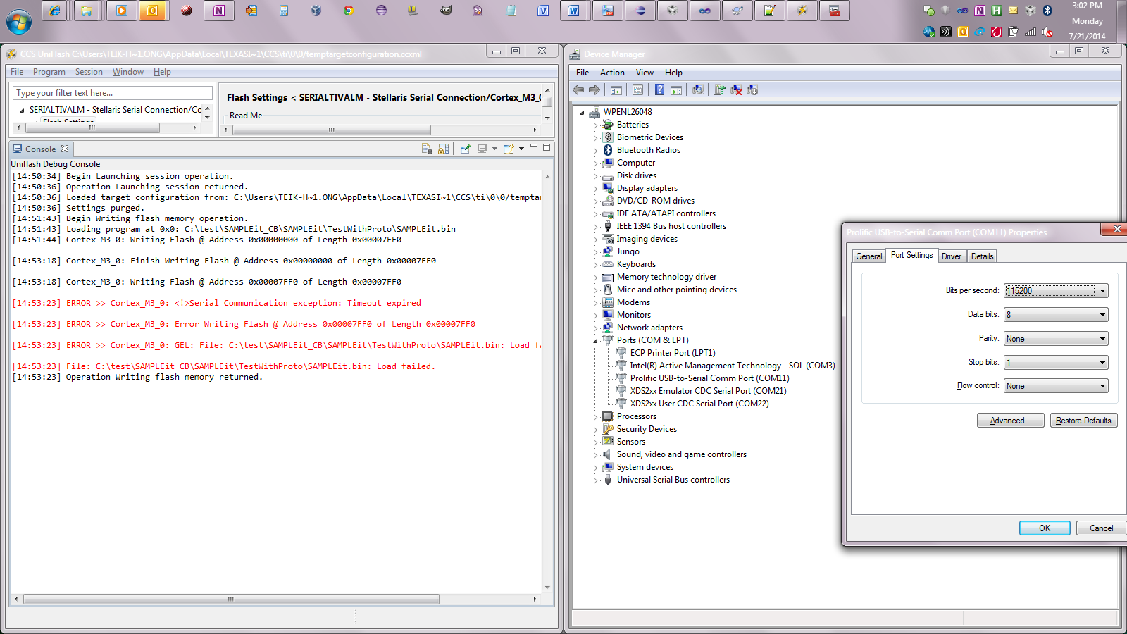
I have an issue using UniFlash tool to flash the .bin image into TM4C123BHPGE. My plan is to use the tool to program a bin image serially into an empty flash. I am pretty sure that I have configured the TM4C123BHPGE BOOTCFG settings properly, and erased the flash completely(using the XDS200 emulator). I verified this by sucessfully using the lmflash programmer tool to programmed the .bin serially. Nevertheless, I have some concerns on the robustness on lmflash as discussed  http://e2e.ti.com/support/microcontrollers/stellaris_arm/f/471/t/351027.aspx and  http://e2e.ti.com/support/microcontrollers/stellaris_arm/f/471/t/351024.aspxI therefore, I was referred to use the uniflash tool instead of lmflash as it is no longer supported.

Thanks.

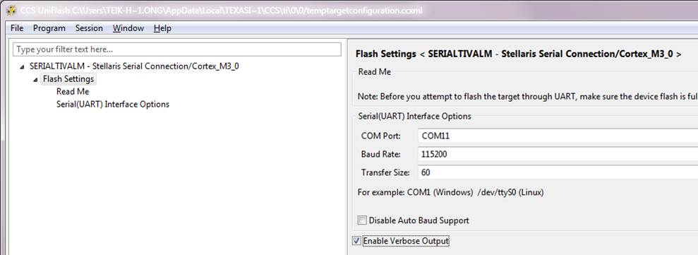
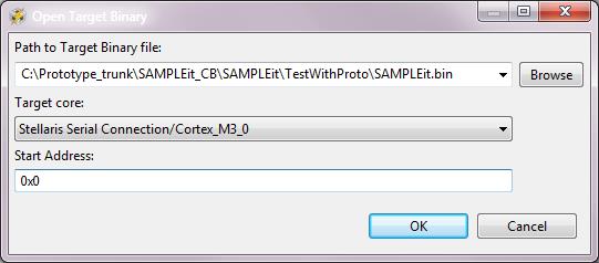
The following is the steps to program: 


  • Hello Ong,

    Are you using XDS200 to download using the serial bootloader?

    Regards

    Amit

  • No, I am just using XDS200 to complete erase the chip, so that upon next power cycle it could enter in ROM-based boot loader mode with auto baud rate detection. After that I disconnect the emulator.

    Next, I hooked up a serial comm connection from my PC(running Windows 7) to the UART0 of TivaC chip to flash the .bin image.

    As I have stated earlier, with the same setup above, I am able to flash using "lmflash" tool but not the "UniFlash" tool.

    Regards. Amit.

    Teik Hong.

  • Hi,

    Did you verified in Device Manager that the active com interface is COM11 as you set it for Uniflash? usually Windows may change when changing the application...

    Petrei

  • Hello Teik Hong,

    Check in the device manager of the PC as to which COM Port is being used. The default in UNIFLASH may not match up with the PC Device Manager.

    Also do check the settings as the default I have seen when using COM is 9600bps

    Regards

    Amit

  • I did as suggested and I still get the same error:


    Per error description, can I say that it program succesfully the region 0x0 @ length 0x7ff0 but when it tried to program the next location, 0x7ff0, it fails? This means that the serial connection is OK?


    I am sure that the serial is OK...every setup I used is similar to how I program with lmflash (successfully).


  • Hello Ong,

    I have used the Stellaris ICDI and it has worked without any issues.

    I would need to try the same with the Serial Cable and UNIFLASH and will get back to you.

    Regards

    Amit

  • Amit,

    Remember to make sure that the main() call the code below so that the TM4C123 chip is setup properly to enter in ROM-based bootloader mode upon next power cycle. Without this, the serial connection won't work in lmflash and I assumed that it won't work in Uniflash either.

    Source code:

    // Registers for setting BOOTCFG

    #define

    BOOTCFG ((volatile

    uint32_t *) (0x400FE000 | 0x1D0))

    #define

    FMA ((volatile

    uint32_t *) (0x400FD000 | 0x000))

    #define

    FMD ((volatile

    uint32_t *) (0x400FD000 | 0x004))

    #define

    FMC ((volatile

    uint32_t *) (0x400FD000 | 0x008))

    //At reset, the following sequence is performed:

    //1. The BOOTCFG register is read. If the EN bit is clear, the ROM Boot Loader is executed.

    //2. In the ROM Boot Loader, the status of the specified GPIO pin is compared with the specified

    //polarity. If the status matches the specified polarity, the ROM is mapped to address 0x0000.0000

    //and execution continues out of the ROM Boot Loader.

    //3. If the EN bit is set or the status doesn't match the specified polarity, the data at address

    //0x0000.0004 is read, and if the data at this address is 0xFFFF.FFFF, the ROM is mapped to

    //address 0x0000.0000 and execution continues out of the ROM Boot Loader.

    //4. If there is data at address 0x0000.0004 that is not 0xFFFF.FFFF, the stack pointer (SP) is loaded

    //from Flash memory at address 0x0000.0000 and the program counter (PC) is loaded from

    //address 0x0000.0004. The user application begins executing.

    void

    Board_initROMbasedBootLoader()

    {

    uint32_t currentConfig = *BOOTCFG;

    // The EN bit has been cleared, hence ROM-based bootloader has been set to load

    // once FLASH is empty (erased to 0xFFFFFFFF).

    if

    (!(currentConfig & 0x100))

    {

    return

    ;

    }

    // The EN bit has NOT been cleared, proceed to clear it to enable ROM-based

    // bootloader.

    // If the EN bit is clear, the ROM Boot Loader is executed.

    uint32_t ROMConfig = currentConfig & ~0x0100;

    *FMD = ROMConfig;

    if

    (*FMD != ROMConfig)

    {

    while

    (1);

    }

    // Committing the value to be changed.

    *FMA = 0x75100000;

    // Write the Flash memory write key and set the COMT bit in the FMC register.

    uint32_t fmc = *FMC;

    *FMC = fmc | 0xA4420000 | 0x00000008;

    // Loop infinitely for user to power cycle.

    while

    (1);

    // The Boot Configuration (BOOTCFG) register requires a POR before the committed

    // changes take effect.


    }


  • Hello Ong,

    DELETE STARTS

    My first point of debug would be to see how the other code you sent is working though the load address is 0x2800. Once I check that out, I would come back on the thread for any setup related questions. Also the code post above : is it in the zip package you have already attached to the previous post?

    DELETE ENDS

    UPDATE: Ignore my last reply as I confused two similar threads on Serial Boot/Bootloader. I have started looking at the issue with the Stellaris ICDI, LMFLASH 1613 and UNIFLASH v3.1

    1. Stellaris ICDI + LMFLASH 1613: Sample code works through UART with Flash Erased

    2. Stellaris ICDI + UNIFLASH v3.1: ONGOING

    3. UART Cable + UNIFLASH v3.1: ONGOING

    Regards

    Amit

  • Also the code post above : is it in the zip package you have already attached to the previous post?

    No, you can copy the code snippet and call it in main().

    Thanks Amit for your help!

  • Hello Ong

    IMP: The Serial Application will work only if the FLASH is Erased. If using the BOOTCFG register then PH7 (based on the setting) must be set to 1 and a POR reset applied for the boot loader to kick start

    1. Stellaris ICDI + LMFLASH 1613: Sample code works through UART with Flash Erased

    2. Stellaris ICDI + UNIFLASH v3.1: Sample code works through UART with Flash Erased

    Without flash erased I get the following message...

    [15:16:09] Begin Writing flash memory operation.
    [15:16:09] Loading program at 0x0: C:\Users\a0876236\workspace_v5_5\boot_demo2\Debug\boot_demo2.bin
    [15:16:09] Cortex_M3_0: Writing Flash @ Address 0x00000000 of Length 0x00000838

    [15:16:14] ERROR >> Cortex_M3_0: <!>Serial Communication exception: Timeout expired

    [15:16:14] ERROR >> Cortex_M3_0: Error Writing Flash @ Address 0x00000000 of Length 0x00000838

    [15:16:14] ERROR >> Cortex_M3_0: GEL: File: C:\Users\a0876236\workspace_v5_5\boot_demo2\Debug\boot_demo2.bin: Load failed.

    [15:16:14] File: C:\Users\a0876236\workspace_v5_5\boot_demo2\Debug\boot_demo2.bin: Load failed.
    [15:16:15] Operation Writing flash memory returned.

    3. UART Cable + UNIFLASH v3.1: ONGOING

    Regards

    Amit

  • Hi Amit,

    Did you manage to try out UART cable + UNIFLASH v3.1?

    Regards,

    Teik Hong

  • Hello Teik-Hong

    Yes, it worked as well. Attached are the screenshot of the settings, load window and the log file

    After loading through the UART Cable I press reset on the board for the blinky program to start

    Regards

    Amit

  • AWESOME. Are your steps any different from mine, described in the first post above? Do you see anything different, or I might miss out?

    Based on your screenshot, it looks the same to what I have done.

    I am suspecting the UART cable, but that same cable was able to program my .bin image with the lmflash tool.


  • Hello Ong Teik,

    I do not see anything different between the screenshots. What I had to do was in the device manager ensure that it was 115200 bps (default was 9600 bps).

    Regards

    Amit

  • I have the same problem, even checked the device manager to make sure the com. settings are correct...

    I was using my own custom board(which works with the lmflash but not the CCS). May I know what evk board that you are using? I have the Tiva C Series ARM MCU EVK board (S/N: 13300601).

    Can you also attached the blinky.bin image?

  • I also replace my USB to serial cable with a dedicated serial cable, however the same error happen, it always fail to program at the following location:


    [15:42:46] Loading program at 0x0: C:\test\SAMPLEit_CB\SAMPLEit\TestWithProto\SAMPLEit.bin

    [15:42:46] Cortex_M3_0: Writing Flash @ Address 0x00000000 of Length 0x00007FF0

    [15:43:46] Cortex_M3_0: Finish Writing Flash @ Address 0x00000000 of Length 0x00007FF0

    [15:43:46] Cortex_M3_0: Writing Flash @ Address 0x00007FF0 of Length 0x00007FF0

    [15:43:51] ERROR >> Cortex_M3_0: <!>Serial Communication exception: Timeout expired

    [15:43:51] ERROR >> Cortex_M3_0: Error Writing Flash @ Address 0x00007FF0 of Length 0x00007FF0

    [15:43:51] ERROR >> Cortex_M3_0: GEL: File: C:\test\SAMPLEit_CB\SAMPLEit\TestWithProto\SAMPLEit.bin: Load failed.

    [15:43:51] File: C:\test\SAMPLEit_CB\SAMPLEit\TestWithProto\SAMPLEit.bin: Load failed.

    [15:43:52] Operation Writing flash memory returned.

  • Hello Ong Tek,

    Can you try LMFLASH with UART once again, to make sure all on the cable is fine? I have also tried the same and it works. Also this time scope the UART TX and RX lines for both failing and passing case.

    I am using one of my own boards, which has the RS232 cable connector.

    Regards

    Amit

  • Amit,

    Everytime the UniFlash fails, I change to the lmflash tool, and it always program successfully. All the h/w setup(like prototype board, cables, images) are the same. The only variable is the tool.


  • Hello Ong

    Is there an image on the device? Can you do a Blank Check and then use UniFlash after power cycling the board.

    I am not sure how I can help you any further as the setup works for me.

    Regards

    Amit