This thread has been locked.

If you have a related question, please click the "Ask a related question" button in the top right corner. The newly created question will be automatically linked to this question.

tlc5916 tm4c123gxl

Other Parts Discussed in Thread: TLC5916

Hi all im having troubles getting this code working

int main(void) {
    uint32_t ui32Index;
    uint32_t ui32Data;
    SysCtlClockSet(SYSCTL_SYSDIV_8 | SYSCTL_USE_PLL |SYSCTL_OSC_MAIN | SYSCTL_XTAL_16MHZ);
    SysCtlPeripheralEnable(SYSCTL_PERIPH_SSI0);
    SysCtlPeripheralEnable(SYSCTL_PERIPH_GPIOA);
    SysCtlPeripheralEnable(SYSCTL_PERIPH_GPIOE);
    GPIOPinConfigure(/*GPIO_PA2_SSI0CLK*/0x00000802);
    GPIOPinConfigure(/*GPIO_PA5_SSI0TX*/ 0x00001402);
    GPIOPinTypeSSI(GPIO_PORTA_BASE,GPIO_PIN_5|GPIO_PIN_3|GPIO_PIN_2);
    GPIOPinTypeGPIOOutput(GPIO_PORTE_BASE, GPIO_PIN_0|GPIO_PIN_1);
    SSIConfigSetExpClk(SSI0_BASE,SysCtlClockGet(),SSI_FRF_TI,SSI_MODE_MASTER,10000,8);
    SSIEnable(SSI0_BASE);
    while(1){
        GPIOPinWrite(GPIO_PORTF_BASE, GPIO_PIN_0|GPIO_PIN_1, 0x02);
        SysCtlDelay(266666);
        for(ui32Index = 0; ui32Index < NUM_SSI_DATA; ui32Index++){
            ui32Data = pui8DataTx[ui32Index];
            SSIDataPut(SSI0_BASE, ui32Data);
            SysCtlDelay(7000000);
        }
        SysCtlDelay(266666);
        GPIOPinWrite(GPIO_PORTF_BASE, GPIO_PIN_1, 0x02);
        SysCtlDelay(266666);
        GPIOPinWrite(GPIO_PORTF_BASE, GPIO_PIN_1, 0x00);
        SysCtlDelay(266666);
        GPIOPinWrite(GPIO_PORTF_BASE, GPIO_PIN_0, 0x00);
        SysCtlDelay(266666);
    }
    return 0;
}

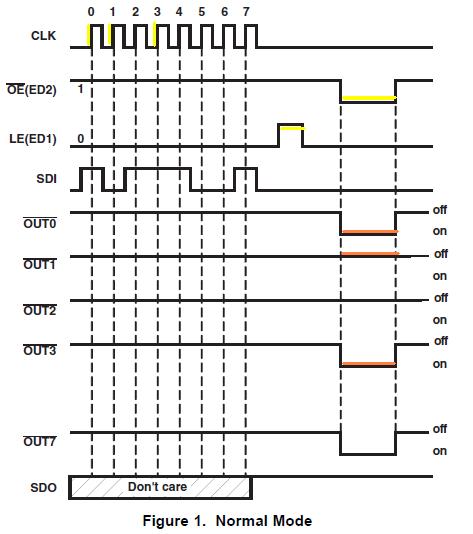
the pins im using is pa2 for clk and pa5 for tx, port e 0 and 1 are oe and le respectively. the led driver chip is the tlc5916. it lights up on board reset but not during anything else. pui8DataTxc is declared as an array. also can someone help me understand SysCtlClockSet(SYSCTL_SYSDIV_8 | SYSCTL_USE_PLL |SYSCTL_OSC_MAIN | SYSCTL_XTAL_16MHZ); and SSIConfigSetExpClk(SSI0_BASE,SysCtlClockGet(),SSI_FRF_TI,SSI_MODE_MASTER,10000,8);

  • HI,

    There a multiple problems with your code, I will try to highlight some of them:

    a) Seems your IDE is not tweaked enough - because you had/have problems in expression: GPIOPinConfigure(/*GPIO_PA2_SSI0CLK*/0x00000802);

    Best thing is to read some launchpad documents/workshop user guide. Start by searching from the main page of your micro.

    b) Do not rush to coding/copy-paste - it "will not work" if you do not read and understand the user manual. For instance, PF0 pin need to be unlocked before first use as GPIO, since it is a NMI configured by default. This is written in the user manual - start reading a chapter a day. Slowly. Search the forum - there are a lot of posting about unlocking - see Tiva forum, not this one.

    c) Until you will know all the functions in driverlib, and before using any function, open the source code and read the description of each function to be used. Try to understand the parameters passed and the return value.

    d) Also, your tlc5916 has a user manual, you need to really understand it first.

    Petrei

  • first off i have read the launchpad documentation and workshop guides and none of them suggest a solution to the GPIOPinConfigure issue other then set device which i already have but i know from embedded systems that i can use the base address to solve that issue. 2 is i didnt rush to copy-paste. 3 i do read the descriptions of each function. the only problem im having is interfacing the tlc5916 which i have read the manual on and the timing. i just need to know what im doing wrong. and im using code composer btw which has worked on my other projects.

  • In defense of poster, "Petrei" - he/I have been here for quite some time - and my conclusion - re your post - was exactly the same!

    Surely he (nor I) seek not to offend - instead we make judgements based upon experience & best, "facts on hand." 

    I made time/effort to construct a suggested Forum Template (resides {thanks to Amit} in a sticky above general posts) which enables relatively new posters to describe their familiarity & usage level w/these complex devices.  Minus that data - Petrei made his assumption.  (which overwhelmingly proves correct - although not so - your specific case)

    Petrei's guidance is dead-on wrt IDE set-up/config.  Even though you report, "has worked on (other) projects" carry over to all subsequent projects is not guaranteed!  (as you've noted)  Devil lurks in such fine detail - suggest that you be bit more "gentle" w/those (unpaid) expending skilled time/effort in your behalf - only seeking your success...

  • ok well im going back trhough the ti workshop and seeing if maybe its an error on my end. but i have done everything from selecting device correctly to loading apps that have already been made and checking settings so unless im missing something very crucial i dont understand why it doesnt accept GPIOPinConfigure(GPIO_PA2_SSI0CLK) but accepts it with the address.

    SysCtlClockSet(SYSCTL_SYSDIV_20_5|SYSCTL_USE_PLL|SYSCTL_OSC_MAIN|SYSCCTL_XTAL_16); this line if i read the documentation says im using the 16mhz clock, using pll which should be 400mhz and uses the main oscillator. and the clock speed should be 19.5mhz roughly
    #include <stdint.h>
    #include <stdbool.h>
    #include "inc/hw_types.h"
    #include "inc/hw_memmap.h"
    #include "driverlib/sysctl.h" //system control libary

    void init(){
        SysCtlClockSet(SYSCTL_SYSDIV_20_5|SYSCTL_USE_PLL|SYSCTL_OSC_MAIN|SYSCTL_XTAL_16MHZ);
    }
     

    PART_TM4C123GH6PM

    TARGET_IS_TM4C123_RB1 found the bug. i didnt add these in.

  • Glad that you found/hooked-in: "TARGET_IS_TM4C123_RB1."   Know that you are far from "alone" in missing that, "gotcha!"  (in a more perfect world - vendor here would not have imposed so exacting (and disabling) a demand upon mere mortals...)

    W/in the Peripheral Driver Library Guide - GPIO chapter - appears: "The available mappings are supplied on a per-device basis in pin_map.h. The PART_IS_<partno> define enables the appropriate set of defines for the device that is being used." 

    Even after many years using these devices - we keep that guide open/ready - all staff desktops...

    I don't like, "SysCtlClockSet(SYSCTL_SYSDIV_20_5     "that 20_5 part in particular!"

    Note that the PLL is first divided by 2 (yielding 200MHz).  Thus - a better parameter - to yield a 20MHz System Clock - would be, "SYSCTL_SYSDIV_10" would it not?

    Again - as Petrei originally noted - the source code for each/every driver lib function is listed & available for your review.  Clearer understanding of what's legal/proper surely follows...

    You are making progress - may be that neither, "Rome - nor TM4C mastery" - results in a single day...

  • im still working out the output enable and latch. and how to do the writes to those at the proper time.

    void ssi_init(){
        SysCtlPeripheralEnable(SYSCTL_PERIPH_SSI0);                                            //enable ssi
        GPIOPinConfigure(GPIO_PA2_SSI0CLK);                                                    //configure pins
        GPIOPinConfigure(GPIO_PA5_SSI0TX);
        GPIOPinConfigure(GPIO_PA3_SSI0FSS);
        GPIOPinTypeSSI(GPIO_PORTA_BASE,GPIO_PIN_5|GPIO_PIN_3|GPIO_PIN_2);                    //set ssi pins
        SSIConfigSetExpClk(SSI0_BASE,SysCtlClockGet(),SSI_FRF_TI,SSI_MODE_MASTER,1000000,8); //config set
        SSIEnable(SSI0_BASE);                                                                //enable ssi
    }

    is that looking better so far or should i change something on it?

  • I don't see where you've acknowledged past issue (you raised) re: "SysCtlClockSet()."   (20_5 jumped out!)   

    From many years in MCU trenches - proceeding minus systematic correction/verification - proves neither efficient not best practice...

    To your new code - some place/where (earlier) you must enable GPIO_PORTA as well.  And - the gpio selected as the chip select for your SPI Slave does not appear here.  (I'm reluctant to scan the entire thread - to search...)  That said - 18:24 posting looks, "good for Gov't Work" (to this reporter).

  • clock is fixed as well. and port a is intialized. thats just the ssi coding. do i need chip select on a pin with output enable and led enable?

  • Pardon - there's just one hour of light left here - and I'm due for a run. 

    I've not read/reviewed the slave spec - save me that effort - post a link - and if time/spirit allows - I'll comment further...

  • http://www.ti.com/lit/ds/symlink/tlc5916.pdf no big hurry. i appreciate all the help.

  • Thanks both for your indulgence (time-wise) and for the Slave Led driver spec.

    Must say - have been in the, "Display biz" for many, many moons - that is one of the most specialized, advanced Led drivers I've encountered.  Quite possibly - it may be, "overkill" for your application.   (Or not - your end use remains silent...)

    To aid you and (the always) interested others - here's the timing chart - your 5916 SPI-Led Driver device:

    As strong (devout) believer in KISS - I've (of course) chosen, "Normal Mode" as it's simplest/fastest to bring to life...  Note the addition of color to this diagram - I've highlighted the (most) critical signals.  Key points follow:

    a) Data is initially presented (via SDI) and clocked in via "CLK's" rising edge.  (yellow highlight)  Your choice of MCU's SPI, "format/mode" must insure that the SPI data emitted by the MCU is valid upon such clock rising edge.

    b) After all 8 data bits have been clocked in - you pulse LE briefly high - then return LE low. (another yellow)  That low going edge "latches in" the (most recent) SDI data. One suspects that "old" data remains resident - until that LE action.

    c) Now that (current) data is latched in - we "present it" to the 8 Led Outputs via, "OE driving low."  (yellow highlight)   While OE is high - each/every output w/in 5916 IC remains, "Off."  Note that this 5916 is a current sinking IC - only the Led cathodes are to be (properly) connected & (potentially) driven low - thus illuminating those Leds.   (orange highlight)

    d) Chip data sheet reveals the timing spec/requirement both for LE & OE.  Note that data must first be clocked in - and then LE toggled and only then OE driven low.  Again - 5916 outputs are on/active only while OE is low.

    Via (intuition channel) I hear your/others' question, "Why not tie OE low?"  Indeed that appears possible - drawbacks may include the (unnecessary) viewing of the garbage as the IC updates and the possibility that the chip may actually require that OE toggle for internal, "housekeeping."  (I do not know)

    e) Signals LE & OE would be derived from MCU's non-SPI GPIO - controlled by you - just after the 8 bit SPI transfer completes.  (it may be possible to invert the SPI_FSS signal (which normally goes low when SPI is active) and feed that to OE.  Such would "automatically" enable your 5916 outputs when SPI transactions complete - and blank the outputs as data, "rattles thru the 5916 shift registers." 

    For simplicity/testing - unless the IC requires "real toggle" @ OE - one suspects that you can tie OE to ground - just "blip" LE post SPI transfer - and observe Led response.  (to my mind - that should be, "Good for (re-distributive) Gov't Work.")

    It may be possible to provide PWM at/beyond 100Hz to provide an alternate or extended, "Led dimming" function - when introduced upon that OE pin.  Again - that's SWAG "pseudo theory" - if of interest you must experiment.

  • so was able to figure it out tying oe to ground and using motorola mode 0 for clocking. it seems at the low clock rate im using oe isnt really required. thanks for all the amazing work. btw the end application is actually a 2d led matrix.

  • Dirk deBoer said:
    thanks for all the amazing work.

    Not too often we humble outsiders hear that!  Thank you - real effort was on your part - focusing - staying on track.

    Note that - imho - your 5916 is a very precise current-sink IC - and very likely "overkill" for a 2D Led project.  You may be able to save effort/expense via far simpler HC/T 595 family, 8 bit, latched shift registers.  While they don't provide the precision current control - they're easily "daisy chained" - enabling 16, 24, 32 (or beyond) Led string control.

    Long ago - we designed/developed precision bar-graphs for Detroit's auto testing.  As Led count exceeded 40 - we switched to FPGA and/or CPLD for, "single chip" solution - again bossed by MCU.  In that case - PWM applied in common to each/every channel - governed the Led string's brightness...

  • yeah i also have some parallel ones that are way easier to interface but i wanted to see if i could start understanding serial. while i dont think i have mastered it not even close im starting to understand more about it. also for those having issues with a stable output add in sysctldelay(1) right after you write the data.

  • Dirk deBoer said:
    issues with a stable output add in sysctldelay(1) right after you write the data.

    Doubt that (unstable output) is in any way/means the MCU's doing!  (ten, hundred to one it's your breadboard - stray capacitance - wiring etc.)

    And - should you be describing any of the serial peripherals (UART, SPI, I2C, CAN) much (most?) all outputs (and their sync'ed clocks) do not allow such delay insertion!  (i.e. SPI & I2C clocks are primarily HW generated w/in the MCU)

    In your particular case you may be encountering a, "hold (or similar) time" violation between final clocked data and your asserion of the LE strobe.  But - I'd not try to generalize that to other applications - absent specs & requirements...