This thread has been locked.

If you have a related question, please click the "Ask a related question" button in the top right corner. The newly created question will be automatically linked to this question.

Problem with counting rising edge using timer(TM4C123GH6PM)

HI,

i have problem with counter.......the result shows keep decreasing value.....

Can someone help me to check what is my problem ?

Description:

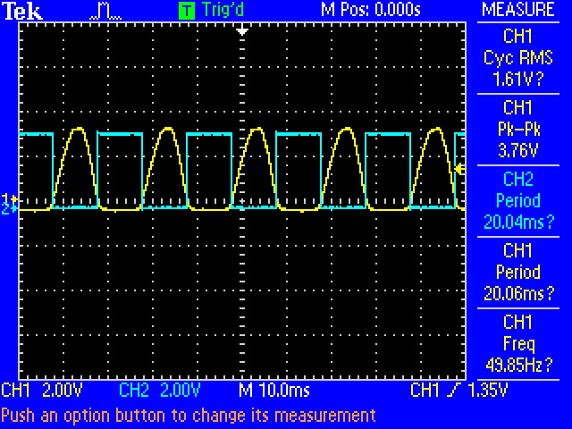
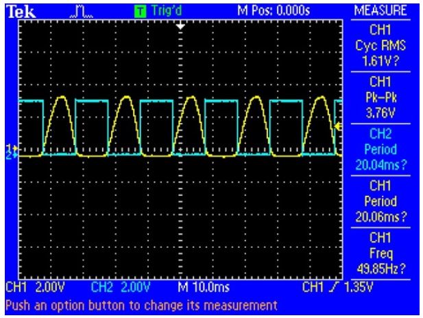
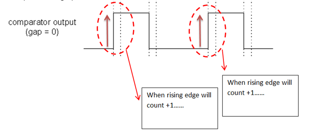
When comparator output rising edge then counter will +1.....

Below is my coding:

#include <stdint.h>

#include <stdbool.h>

#include <stdio.h>

#include "inc/hw_ints.h"

#include "inc/hw_memmap.h"

#include "inc/hw_types.h"

#include "inc/hw_gpio.h"

#include "driverlib/gpio.h"

#include "driverlib/sysctl.h"

#include "driverlib/systick.h"

#include "driverlib/pin_map.h"

#include "driverlib/comp.h"

#include "driverlib/debug.h"

#include "driverlib/timer.h"


unsigned long g_ulFlags;

unsigned long timer;


#ifdef DEBUG

void

__error__(char *pcFilename, unsigned long ulLine)

{

}

#endif


char display[50];

int main(void)

{

    SysCtlClockSet(SYSCTL_SYSDIV_1 | SYSCTL_USE_OSC | SYSCTL_OSC_MAIN |  SYSCTL_XTAL_8MHZ);


    SysCtlPeripheralEnable(SYSCTL_PERIPH_GPIOF);


    GPIODirModeSet(GPIO_PORTF_BASE, 0x01, GPIO_DIR_MODE_OUT);

    GPIOPadConfigSet(GPIO_PORTF_BASE, 0x01,GPIO_STRENGTH_2MA,GPIO_PIN_TYPE_STD);

    HWREG(GPIO_PORTF_BASE + GPIO_O_LOCK) = GPIO_LOCK_KEY;

    HWREG(GPIO_PORTF_BASE + GPIO_O_CR) |= 0x01;

    HWREG(GPIO_PORTF_BASE + GPIO_O_DEN) |= 0x01;

    HWREG(GPIO_PORTF_BASE + GPIO_O_LOCK) = 0;

    HWREG(GPIO_PORTF_BASE + GPIO_O_AFSEL) |= 0x1;

    HWREG(GPIO_PORTF_BASE + GPIO_O_PCTL) &= ~(0xF);

    HWREG(GPIO_PORTF_BASE + GPIO_O_PCTL) |= 0x9;


   GPIOPinTypeGPIOOutput (GPIO_PORTF_BASE,GPIO_PIN_1|GPIO_PIN_2|GPIO_PIN_3);


   SysCtlPeripheralEnable(SYSCTL_PERIPH_COMP0);

   ComparatorConfigure(COMP_BASE, 0,

                                     (COMP_TRIG_NONE | COMP_INT_BOTH | COMP_ASRCP_REF | COMP_OUTPUT_INVERT));

   ComparatorRefSet(COMP_BASE, COMP_REF_0V);


   SysCtlPeripheralEnable(SYSCTL_PERIPH_TIMER2);


   GPIOPinConfigure(GPIO_PF4_T2CCP0);

   GPIOPinTypeTimer(GPIO_PORTF_BASE, GPIO_PIN_4);


   TimerConfigure(TIMER2_BASE, TIMER_CFG_A_CAP_COUNT);

   TimerLoadSet(TIMER2_BASE, TIMER_A, 1);

   TimerControlEvent(TIMER2_BASE,TIMER_A,TIMER_EVENT_POS_EDGE);


   TimerEnable(TIMER2_BASE, TIMER_A);

     while(1)

    {

       timer=TimerValueGet(TIMER2_BASE,TIMER_A);

     }

}


 Regards,

Dorene

  • Hello Dorene,

    Please replace TimerConfigure(TIMER2_BASE, TIMER_CFG_A_CAP_COUNT);

    with

    TimerConfigure(TIMER2_BASE, TIMER_CFG_A_CAP_COUNT_UP);

    Regards

    Amit

  • dorene jong said:
    ComparatorRefSet(COMP_BASE, COMP_REF_0V);

    Does setting that reference voltage to 0V make great sense?  Can you insure that the "real world" signal - applied to the comparator's other input - can (ever) drop beneath this 0V level?  (if not - it's likely the comparator will be unable to toggle)

    And - earlier you, "GPIODirModeSet() and GPIOPadConfigSet()" famed PF0 - prior to its unlocking. 

  • hi Amit,

    What should i do if i want to show my output is keep increasing?Example:1...2...3....4....5...6...
    Currently my output is showing 0...1.....0...1...Isn't if my coding use in interrupt will be better?

    Regards,

    Dorene

  • Hi!

    I'm currently working on a simple frequency counter which should count positive edges. The time gate signal is coming from an external device and triggers a gpio interrupt which is just working fine. The external edges are produced by the Comparator.

    I configured timer #2 as an input edge counter. Can someone help me to check what is my problem ?

    What should i do if i want to show my output is keep increasing?Example:1...2...3....4....5...6...
    Currently my output is showing 0...1.....0...1...

    Here is my coding:

    #include <stdint.h>

    #include <stdbool.h>

    #include <stdio.h>

    #include "inc/hw_ints.h"

    #include "inc/hw_memmap.h"

    #include "inc/hw_types.h"

    #include "inc/hw_gpio.h"

    #include "driverlib/gpio.h"

    #include "driverlib/sysctl.h"

    #include "driverlib/systick.h"

    #include "driverlib/pin_map.h"

    #include "driverlib/comp.h"

    #include "driverlib/debug.h"

    #include "driverlib/timer.h"


    unsigned long g_ulFlags;

    unsigned long timer;


    #ifdef DEBUG

    void

    __error__(char *pcFilename, unsigned long ulLine)

    {

    }

    #endif


    char display[50];

    int main(void)

    {

        SysCtlClockSet(SYSCTL_SYSDIV_1 | SYSCTL_USE_OSC | SYSCTL_OSC_MAIN |  SYSCTL_XTAL_8MHZ);


        SysCtlPeripheralEnable(SYSCTL_PERIPH_GPIOF);


        GPIODirModeSet(GPIO_PORTF_BASE, 0x01, GPIO_DIR_MODE_OUT);

        GPIOPadConfigSet(GPIO_PORTF_BASE, 0x01,GPIO_STRENGTH_2MA,GPIO_PIN_TYPE_STD);

        HWREG(GPIO_PORTF_BASE + GPIO_O_LOCK) = GPIO_LOCK_KEY;

        HWREG(GPIO_PORTF_BASE + GPIO_O_CR) |= 0x01;

        HWREG(GPIO_PORTF_BASE + GPIO_O_DEN) |= 0x01;

        HWREG(GPIO_PORTF_BASE + GPIO_O_LOCK) = 0;

        HWREG(GPIO_PORTF_BASE + GPIO_O_AFSEL) |= 0x1;

        HWREG(GPIO_PORTF_BASE + GPIO_O_PCTL) &= ~(0xF);

        HWREG(GPIO_PORTF_BASE + GPIO_O_PCTL) |= 0x9;


       GPIOPinTypeGPIOOutput (GPIO_PORTF_BASE,GPIO_PIN_1|GPIO_PIN_2|GPIO_PIN_3);


       SysCtlPeripheralEnable(SYSCTL_PERIPH_COMP0);

       ComparatorConfigure(COMP_BASE, 0,

                                         (COMP_TRIG_NONE | COMP_INT_BOTH | COMP_ASRCP_PIN0 | COMP_OUTPUT_INVERT));

       SysCtlPeripheralEnable(SYSCTL_PERIPH_TIMER2);


       GPIOPinConfigure(GPIO_PF4_T2CCP0);

       GPIOPinTypeTimer(GPIO_PORTF_BASE, GPIO_PIN_4);


       TimerConfigure(TIMER2_BASE, TIMER_CFG_A_CAP_COUNT_UP);

       TimerLoadSet(TIMER2_BASE, TIMER_A, 1);

       TimerControlEvent(TIMER2_BASE,TIMER_A,TIMER_EVENT_POS_EDGE);


       TimerEnable(TIMER2_BASE, TIMER_A);

         while(1)

        {

           timer=TimerValueGet(TIMER2_BASE,TIMER_A);

         }

    }


     Regards,

    Dorene


  • Hello Dorene,

    The issue is with the TimerLoadSet where you are loading the value 1. As a result it is counting 0.1.0.1

    You need to set it to a higher value such that you would get an interrupt when the Match is reached and the counter would be restarted

    Regards

    Amit

  • Dear Amit,

     I tried to changed it into 0xFFF but the result shows me not +1(Results:29,11,190,16,20)....

    what the happen?

    i want the output can be show as 1.2.3.4.5.6.7.8.9.10.....Can you guide me ?

    Regards,

    Dorene

  • Hello Dorene,

    How fast is the input edge coming to the TM4C Timer Counting the edges?

    Regards

    Amit

  • Hi Amit, 

    My input edge is from the edges are produced by the comparator (from AC plug through a step down transformer then use the voltage divider into 2.33v supply into Co-)

    Regards,

    Dorene

  • Hello Dorene,

    For a 50/60Hz input signal the counter should not be changing so fast. Did you check that the comparator output is clean and does not have spurious edges?

    Regards

    Amit

  • Dear Amit,

    May i know how to set the output become 0 when my input is off?(Once i off the result wont go to 0, maintain the last number where it stop....)

    Regards,

    Dorene

  • Hi Amit,

    i think is clean ....here is my output result.....

    Regards,

    Dorene

  • Hello Dorene,

    The signal being clean will be seen under high resolution at the edge. At 10ms per division, small spikes of few us or ns may not be resolved with a scope. You will have to move the resolution to a better one and then capture it;

    I have just done the timer configuration in tm4c129 devices with a very clean 50Hz square wave and it counts just the way it should.

    Alternatively, if there is a noisy edge and since you want to capture it cleanly without external filter, you can use the GPIO Rising Edge Capture, and put a delay of few 10s of us to count the edge before clearing the Rising Edge Interrupt. Of course it will involve CPU going to the Interrupt Handler at every rising edge, but I would believe that it would be a much simpler approach.

    Regards

    Amit

  • Dear Amit,

    May i know how to set the output become 0 when my input is off?(Once i off the result wont go to 0, maintain the last number where it stop....)

    Regards,

    Dorene

  • Hello Dorene

    You can disable the timer using GPTMCTL.TnEN bit and enable it to make it reset the internal counter to 0

    Regards

    Amit

  • hi Amit,

    isnt add this into the main() ?

    TimerDisable(TIMER2_BASE, TIMER_A)?

    Regards,

    Dorene

  • Hello Dorene

    Yes, that should do.

    Also please check the edge of the signals on the scope under high resolution or move to the GPIO based approach, I checked cb1's post also and it is a strong point that you need to consider when using the comparator.

    Regards

    Amit

  • Hi,

    i would like to remind you the timer in edge counting (up) is not a totalizer/accumulator one, it is just a finite number counter. You always need a second configuration step, to fill up the match register in order to have a triggered event when the counter value is equal to match register. 

    Petrei

  • Hi Amit,

    I'm not quite understand ....if i need to re-enable the timer, ensure that the TnEN bit is cleared and

    repeat steps 4 through 8.

    4. Configure the type of event(s) that the timer captures by writing the TnEVENT field of the GPTM
    Control (GPTMCTL) register.

    5. Program registers according to count direction:
    ■ In up-count mode, the timer counts from 0x0 to the value in the GPTMTnMATCHR and
    GPTMTnPMR registers. Note that when executing an up-count, the value of the GPTMTnPR
    and GPTMTnILR must be greater than the value of GPTMTnPMR and GPTMTnMATCHR.

    6. If interrupts are required, set the CnMIM bit in the GPTM Interrupt Mask (GPTMIMR) register.

    7. Set the TnEN bit in the GPTMCTL register to enable the timer and begin waiting for edge events.

    8. Poll the CnMRIS bit in the GPTMRIS register or wait for the interrupt to be generated (if enabled).
    In both cases, the status flags are cleared by writing a 1 to the CnMCINT bit of the GPTM
    Interrupt Clear (GPTMICR) register.

    which mean i have to use interrupt?

    Regards,

    Dorene

  • Hello Dorene,

    Yes. When the Match occurs and the polling of GPTMRIS or interrupt is generated you need to call TimerDisable and then TimerEnable to reset the actual edge counter to 0.

    Regards

    Amit

  • Hi Amit,
    Here is my new coding~(but why my output keep showing 0.....) Can you check for me what is my problem?
    #include <stdint.h>
    #include <stdbool.h>
    #include <stdio.h>
    #include "inc/hw_ints.h"
    #include "inc/hw_memmap.h"
    #include "inc/hw_types.h"
    #include "inc/hw_gpio.h"
    #include "driverlib/gpio.h"
    #include "driverlib/sysctl.h"
    #include "driverlib/systick.h"
    #include "driverlib/pin_map.h"
    #include "driverlib/comp.h"
    #include "driverlib/interrupt.h"
    #include "driverlib/debug.h"
    #include "driverlib/timer.h"
    unsigned long g_ulFlags;
    unsigned long timer;
    #ifdef DEBUG
    void
    __error__(char *pcFilename, unsigned long ulLine)
    {
    }
    #endif
    char display[50];
    Timer2IntHandler(void)
    {
        TimerIntClear(TIMER2_BASE, TIMER_TIMA_TIMEOUT);
        timer=TimerValueGet(TIMER2_BASE,TIMER_A);
    }
    int main(void)
    {
        SysCtlClockSet(SYSCTL_SYSDIV_1 | SYSCTL_USE_OSC | SYSCTL_OSC_MAIN |  SYSCTL_XTAL_8MHZ);
        SysCtlPeripheralEnable(SYSCTL_PERIPH_GPIOF);
        GPIODirModeSet(GPIO_PORTF_BASE, 0x01, GPIO_DIR_MODE_OUT);
        GPIOPadConfigSet(GPIO_PORTF_BASE, 0x01,GPIO_STRENGTH_2MA,GPIO_PIN_TYPE_STD);
        HWREG(GPIO_PORTF_BASE + GPIO_O_LOCK) = GPIO_LOCK_KEY;
        HWREG(GPIO_PORTF_BASE + GPIO_O_CR) |= 0x01;
        HWREG(GPIO_PORTF_BASE + GPIO_O_DEN) |= 0x01;
        HWREG(GPIO_PORTF_BASE + GPIO_O_LOCK) = 0;
        HWREG(GPIO_PORTF_BASE + GPIO_O_AFSEL) |= 0x1;
        HWREG(GPIO_PORTF_BASE + GPIO_O_PCTL) &= ~(0xF);
        HWREG(GPIO_PORTF_BASE + GPIO_O_PCTL) |= 0x9;
       GPIOPinTypeGPIOOutput (GPIO_PORTF_BASE,GPIO_PIN_1|GPIO_PIN_2|GPIO_PIN_3);
       SysCtlPeripheralEnable(SYSCTL_PERIPH_COMP0);
       ComparatorConfigure(COMP_BASE, 0,
         (COMP_TRIG_NONE | COMP_INT_BOTH | COMP_ASRCP_PIN0 | COMP_OUTPUT_INVERT));
       SysCtlPeripheralEnable(SYSCTL_PERIPH_TIMER2);
       GPIOPinConfigure(GPIO_PF4_T2CCP0);
       GPIOPinTypeTimer(GPIO_PORTF_BASE, GPIO_PIN_4);
       IntMasterEnable();
       TimerConfigure(TIMER2_BASE, TIMER_CFG_A_CAP_COUNT_UP);
       TimerLoadSet(TIMER2_BASE, TIMER_A, 0xFFFF);
       TimerMatchSet(TIMER2_BASE, TIMER_A, 0);
       TimerControlEvent(TIMER2_BASE,TIMER_A,TIMER_EVENT_POS_EDGE);
       IntEnable(INT_TIMER2A);
       TimerIntEnable(TIMER2_BASE, TIMER_TIMA_TIMEOUT);
       TimerEnable(TIMER2_BASE, TIMER_A);
        while(1)
        {
         }
    }
    Regards,
    Dorene
  • This has devolved into Basic Engineering 101 - good read of MCU manual and basic engineering education really required.

    Any engineering design employing the set-point as revealed here - simply is asking (screaming, really) for trouble!

    Classically that set-point would be set, "mid-signal" not to either signal, "extreme!"

    Thanks to Amit for his recognitionagreement (this critical point - neglected/avoided by poster) - poster appears much challenged here - perhaps her firm can provide engineering basics - so that real MCU issues may receive proper attention/focus...  (although - "Tiva MCUs and Basic Engineering" - as NEW Forum Name - does have a certain, "ring.")

    How much, non MCU-centric HELP - is too much?  When should the sponsoring firm take responsibility for, "proper (basic) training/educating" of staff?  Or - is the Tiva forum to continue as, "tech training, dumping ground?"