This thread has been locked.

If you have a related question, please click the "Ask a related question" button in the top right corner. The newly created question will be automatically linked to this question.

Strange problem in I2C!!

Other Parts Discussed in Thread: TM4C1294NCPDT

Dear friends,

For the last month I have been learning and working on I2C protocol, theoretically everything is OK, but when I tried to apply my knowledge on the real board a problem which is gonna to lead me to crazy rised!!!

I always get strange things on the bus! I will put my code and the logic analyzer photo bellow.

I just want to say that I have tried almost everything to solve that!!! but no results. and note, that I tried loop back example and it worked. but my code didn't work :(

The details of the experiment: TIVA C Connected launchpad (TM4C1294NCPDT MCU) with two 4K7 pull up resistors on the clock and data buses connected with 5V from TIVA board.
- I tried to use both I2C0 and I2C2 modules with no results!
hope that you help me cuz I am totally disappointed :(


#include "inc/tm4c1294ncpdt.h"
#include <stdbool.h>
#include <stdint.h>
#include "inc/hw_memmap.h"
#include "driverlib/gpio.h"
#include "driverlib/sysctl.h"
#include "inc/hw_types.h"
#include "driverlib/uart.h"
#include "utils/uartstdio.h"
#include "inc/hw_i2c.h"
#include "driverlib/i2c.h"
#include "driverlib/rom.h"
#include "driverlib/pin_map.h"

#define SLAVE_ADDRESS 0x3C

void
InitConsole(void)
{
    //
    // Enable GPIO port A which is used for UART0 pins.
    // TODO: change this to whichever GPIO port you are using.
    //
    SysCtlPeripheralEnable(SYSCTL_PERIPH_GPIOA);

    //
    // Configure the pin muxing for UART0 functions on port A0 and A1.
    // This step is not necessary if your part does not support pin muxing.
    // TODO: change this to select the port/pin you are using.
    //

    GPIOPinConfigure(GPIO_PA0_U0RX);
    GPIOPinConfigure(GPIO_PA1_U0TX);

    //
    // Enable UART0 so that we can configure the clock.
    //
    SysCtlPeripheralEnable(SYSCTL_PERIPH_UART0);

    //
    // Use the internal 16MHz oscillator as the UART clock source.
    //
    UARTClockSourceSet(UART0_BASE, UART_CLOCK_PIOSC);

    //
    // Select the alternate (UART) function for these pins.
    // TODO: change this to select the port/pin you are using.
    //
    GPIOPinTypeUART(GPIO_PORTA_BASE, GPIO_PIN_0 | GPIO_PIN_1);

    //
    // Initialize the UART for console I/O.
    //
    UARTStdioConfig(0, 115200, 16000000);
}

int
main(void)
{
    uint32_t pui32DataTx;

    SysCtlClockSet(SYSCTL_SYSDIV_1 | SYSCTL_USE_OSC | SYSCTL_OSC_MAIN |
                   SYSCTL_XTAL_16MHZ);
    SysCtlPeripheralEnable(SYSCTL_PERIPH_I2C2);
    SysCtlPeripheralEnable(SYSCTL_PERIPH_GPION);
    GPIOPinConfigure(GPIO_PN5_I2C2SCL);
    GPIOPinConfigure(GPIO_PN4_I2C2SDA);
    GPIOPinTypeI2CSCL(GPIO_PORTN_BASE, GPIO_PIN_5);
    GPIOPinTypeI2C(GPIO_PORTN_BASE, GPIO_PIN_4);
    I2CMasterInitExpClk(I2C2_BASE, SysCtlClockGet(), false);

    InitConsole();

    I2CMasterSlaveAddrSet(I2C2_BASE, SLAVE_ADDRESS, false);

    UARTprintf("I2C2 Initialized.\n");

    pui32DataTx = '4';

    I2CMasterDataPut(I2C2_BASE, pui32DataTx);
    I2CMasterControl(I2C2_BASE, I2C_MASTER_CMD_SINGLE_SEND);

    while(I2CMasterBusy(I2C2_BASE));

    UARTprintf("Sent: '%c'\n", pui32DataTx);

    return(0);
}

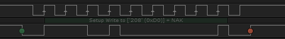
This is what I get on the buses with the previous code. Where is the address!!?? where is the data!! I just see start condition and then nothing !!!

Thank you in advance for your help :)

  • Hello Mohammed,

    first of all let me point out that the SysCtlClockSet and SysCtlClockGet function is meant for TM4C123 devices and not TM4C129. This needs to be corrected first. The correct Clock API is SysCtlClockFreqSet and the return value of this function is the correct System Clock actually set.

    Secondly, TM4C129 does not have a 5V tolerant IO. So what you may be doing is something not correct for device operation.

    Regards

    Amit

  • Hello Amit :), you are the best!!! that really solved my problem! Thank's alot.

    btw, I meant in 5V from the mcu, the 5v on the board from usb connection.

    I want to ask you how to ignore the acknowlede checking in master device (I mean in my case above (in my code) How can I let the master to keep sending data although no acknowledge is received?)

    again, thank you alot for your help :)

    best regards,

    Mohammed.

  • Hello Mohammed

    The master of the I2C controller cannot ignore the Acknowledge checking, else it would be violating the I2C Specification. The only way you may do that is to implement I2C protocol using GPIO bit banging. There is a sample code in the TIVAWare installation under examples/peripherals/i2c/soft_i2c.c that you may use as reference.

    But from the I2C Controller perspective, it does not allow ACK pulse to be ignored as it is an important indicator in terms of transfer.

    Regards

    Amit

  • In my code above, now I can see the address and (r/w bit) on the bus using logic analyzer, but then I see stop bit, and no data is being sent, is that because there is no acknowledge, right?

  • Hello Mohammed

    That is what is very strange. Even if there is NACK there should be 9 SCL Clock pulses for the address phase

    7 for address, 1 for r/w and 1 for ack.

    Also looking at the scope plot it is not clear as to what is the time and voltage scale of the plot. I might suggest decreasing the Pull Value to 1K and reducing the IO voltage to 3.3V for a proper I2C Address Frame. Do send in the scope plot with the updated data on time, voltage scale.

    Regards

    Amit

  • Hello Amit, no no everything now is OK, here is my new logic analyzer, but I mean, there should be data pulses on the bus, but I can not see the data pulses (we can see just start, address, r/w and stop bit), but no data.

    were the data not being sent because there is NAK?

  • Hello Mohammed,

    Thanks for the info. You are right, since the Address is NAK the controller does not have a valid I2C Slave to send the data byte to or receive data from. So it would stop the I2C Transaction.

    Regards

    Amit

  • Now I hope everything has been solved, thank you very much :)

    Best regards,

    Mohammed.

  • Sorry for confusing you, I have a new problem now!

    when I connect the buses to a device (on my bus I have RTC and EEPROM), the values on the bus are different now! and I just changed the address of the device to (0x68), but something goes wrong.

    here is my logic analyzer photo when I connect the buses to the devices:

    we can see as the there is missynchronizing from data and clk buses, as we can see that on data bus the data is 1101000 (0x68) (but not at the proper time). and there is a problem on clk bus..

    And the data are good when I disconnect the devices.

    Any suggesions?

  • In either case (slave in or out) data is now, "coincident" w/SCL - and that should not be!  Earlier posts showed data clocked in via SCL's rising edge - you've done something (likely w/SSI format) to vary from initial SSI setting...

    Note that now - but for that initial 2 data bits - data syncs to SCL - which is non-standard (unwanted) - my book...

  • I didn't understand you very well, could you explain that please in another way? and what is SSI?

    and I still get NAK, although I have my device on the bus!

  • Hello Mohammed,

    I believe the load on the bus is high when the devices are connected. The issue is on the SCL Line. I would suggest changing the Pull Up on SCL to 1K ohms.

    Regards

    Amit

  • Hello Amit,

    Now I believe that there is something wrong in my logic analyzer!! I will attach bellow both logic analyzer and oscilloscope graphs. But I still get no ACK altough my device is on the bus.

    I am using this module, could you please check it and see if I am doing something wrong?

    http://www.ebay.com/itm/Arduino-I2C-RTC-DS1307-AT24C32-Real-Time-Clock-Module-For-AVR-ARM-PIC-SMD-/170910326110?pt=LH_DefaultDomain_0&hash=item27cb0c9d5e

    I just connected VCC , GND, SCL and SDA (just these four pins). and pull up resistors are there(I tried both 4K7 and 1 K). and the address is 0x68.

    Here is the attached graphs: see the diffrence between Osc and Logic Analyzer signal!!

  • Hello Mohammed,

    I have not used this module. I think you are trying to access DS1307 which has Slave Address of 0x68? If possible check that the timing are being met as per the DS1307 data sheet, as it is the only thing that would be hampering the I2C Communication.

    IMP: Please note that TM4C129 does not have 5V tolerant IO's. I would suggest using a 3.3V module if there is any.

    Regards

    Amit

  • Hello Amit,

    OK now everything goes ok :)

    I will explain briefly how:

    at first when I used:

    SysCtlClockFreqSet((SYSCTL_XTAL_25MHZ | SYSCTL_OSC_MAIN | SYSCTL_USE_PLL | SYSCTL_CFG_VCO_480), 120000000);

    I could find just the address of the EEPROM on the bus.

    but when I changed clock speed into:

    SysCtlClockFreqSet((SYSCTL_XTAL_25MHZ | SYSCTL_OSC_MAIN | SYSCTL_USE_PLL | SYSCTL_CFG_VCO_480), 60000000);

    I could find both devices and sending data goes properly (almost)  :)

    Why did that solve the problem and how can I avoid this kind of problems in the future? (Actually I know why :D it is because the clock was very high for I2C module in the MCu but how can I know that? (I solved that by chance))

    I still have a little problem(not really a problem) when I am doing burst writing:

    	ROM_I2CMasterDataPut(ulI2CBase, 0x05);
    	ROM_I2CMasterControl(ulI2CBase, I2C_MASTER_CMD_BURST_SEND_START);
    	ROM_SysCtlDelay(500);
    	ROM_I2CMasterDataPut(ulI2CBase, 0x04);
    	ROM_I2CMasterControl(ulI2CBase, I2C_MASTER_CMD_BURST_SEND_CONT);

    I have to put this delay between the processes (cuz when I remove it I just get 0x04 two times!), indicates that it works very fast for I2C module.
    What is the most proper delay and what to do in other speed modes? ( 400Kb, 1Mb or 3.3Mb)?

    I think for this topic these are my last questions :)

  • Hello Mohammed,

    My suspicion was right that the timing at the Slave end was not meeting looking at the scope snapshot. The other thing of adding delay is that it can be replaced with I2CMasterBusy API to check if the I2C is busy sending the last command. However on TM4C129 due to high speed of the core it may at times miss this. So suggested way of sending commands is

    while(!I2CMasterBusy(ulI2CBase));

    while(I2CMasterBusy(ulI2CBase));

    Regards

    Amit

  • Thank you very much everything is OK now, even the RTC module haven't worked yet, but I think I need just more reading in the datasheet.

    I think you meant while(I2CMasterBusy(ulI2CBase));

    (without not mark (!))

    Again, thank's alot for your helping Amit.

    Best regards,

    Mohammed.

  • Mohammed Noureldin said:
    I think you meant while(I2CMasterBusy(ulI2CBase));

    He did not!   That new (strange) usage is brought about by the new 129 class MCU.  You'd do well to follow his advice...  (and welcome to the rebirth of "MCU Class" (impacting existing library SW) which did not end well for past Stellaris M3s...)

  • That made my app stuck in that loop! (because when the pointer arrives that place for the first time, so it will stay there! cuz it is not busy).

  • Oh sorry! I didn't notice that there are two phrases, one with (!) and another without (!).

    Now everything is clear, thank's alot again :) .

    Best regards,

    Mohammed.