This thread has been locked.

If you have a related question, please click the "Ask a related question" button in the top right corner. The newly created question will be automatically linked to this question.

Load program Error in TM4C123GH6PZT

Hi,

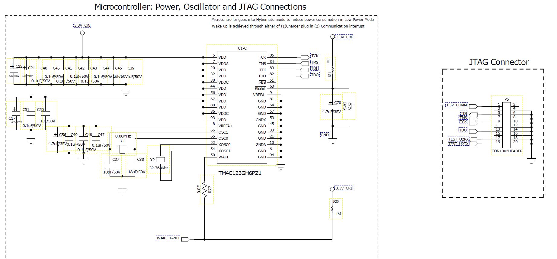
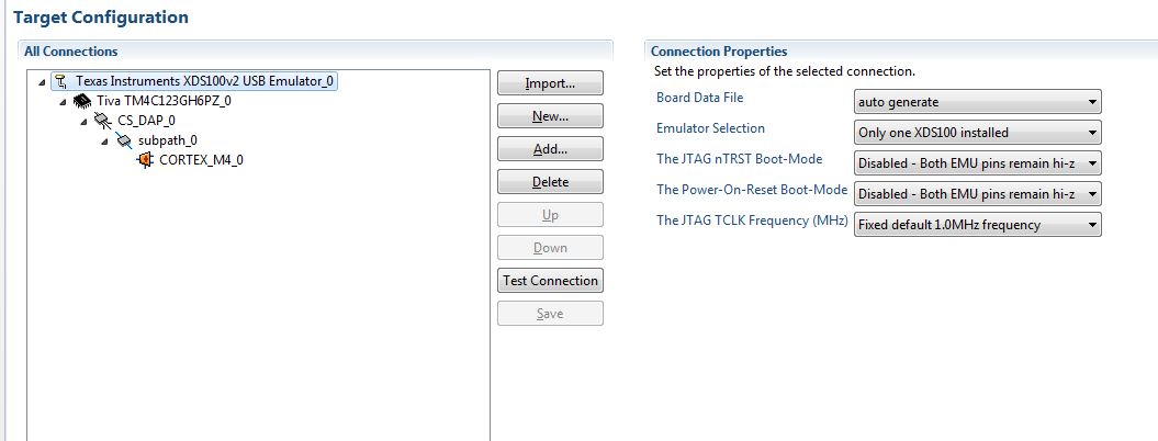
                      I m using TM4C123GH6PZT controller and CCS6.0. While flashing the code in controller i m getting load Program error. i checked the voltages in controller and JTAG, I m getting 3.2 V. What can be the reason for getting this error.

Thanks,

Yuvaraj N

  • Hello Yuvaraj,

    Was this the first time you were trying to load a program?

    There is a utility called Test Connection in CCS which can be accessed by double clicking the ccxml file in the project. Does it Pass or Fail?

    Regards

    Amit

  • Hi Amit,

                        Thanks for reply. yes first time i am trying to load program on tiva using stellaries. Just for your information i am using stellaris incircuit debugger which is connected to usb port of my computer. i couldn't see test button enabled in test configuration with my setup. 

  • Hi Amit,

                       I tried with XDS100v2 USB Emulator. in this test configuration is enabled. and i m getting following message in log file.

    [Start: Texas Instruments XDS100v2 USB Emulator_0]
    
    Execute the command:
    
    %ccs_base%/common/uscif/dbgjtag -f %boarddatafile% -rv -o -F inform,logfile=yes -S pathlength -S integrity
    
    [Result]
    
    
    -----[Print the board config pathname(s)]------------------------------------
    
    C:\Users\AE0077\AppData\Local\TEXASI~1\CCS\
    CCS_6_b4\0\0\BrdDat\testBoard.dat
    
    -----[Print the reset-command software log-file]-----------------------------
    
    This utility has selected a 100- or 510-class product.
    This utility will load the adapter 'jioserdesusb.dll'.
    The library build date was 'Feb 28 2014'.
    The library build time was '04:03:07'.
    The library package version is '5.1.440.0'.
    The library component version is '35.34.40.0'.
    The controller does not use a programmable FPGA.
    The controller has a version number of '4' (0x00000004).
    The controller has an insertion length of '0' (0x00000000).
    This utility will attempt to reset the controller.
    This utility has successfully reset the controller.
    
    -----[Print the reset-command hardware log-file]-----------------------------
    
    The scan-path will be reset by toggling the JTAG TRST signal.
    The controller is the FTDI FT2232 with USB interface.
    The link from controller to target is direct (without cable).
    The software is configured for FTDI FT2232 features.
    The controller cannot monitor the value on the EMU[0] pin.
    The controller cannot monitor the value on the EMU[1] pin.
    The controller cannot control the timing on output pins.
    The controller cannot control the timing on input pins.
    The scan-path link-delay has been set to exactly '0' (0x0000).
    
    -----[The log-file for the JTAG TCLK output generated from the PLL]----------
    
    There is no hardware for programming the JTAG TCLK frequency.
    
    -----[Measure the source and frequency of the final JTAG TCLKR input]--------
    
    There is no hardware for measuring the JTAG TCLK frequency.
    
    -----[Perform the standard path-length test on the JTAG IR and DR]-----------
    
    This path-length test uses blocks of 512 32-bit words.
    
    The test for the JTAG IR instruction path-length succeeded.
    The JTAG IR instruction path-length is 4 bits.
    
    The test for the JTAG DR bypass path-length succeeded.
    The JTAG DR bypass path-length is 1 bits.
    
    -----[Perform the Integrity scan-test on the JTAG IR]------------------------
    
    This test will use blocks of 512 32-bit words.
    This test will be applied just once.
    
    Do a test using 0xFFFFFFFF.
    Scan tests: 1, skipped: 0, failed: 0
    Do a test using 0x00000000.
    Scan tests: 2, skipped: 0, failed: 0
    Do a test using 0xFE03E0E2.
    Scan tests: 3, skipped: 0, failed: 0
    Do a test using 0x01FC1F1D.
    Scan tests: 4, skipped: 0, failed: 0
    Do a test using 0x5533CCAA.
    Scan tests: 5, skipped: 0, failed: 0
    Do a test using 0xAACC3355.
    Scan tests: 6, skipped: 0, failed: 0
    All of the values were scanned correctly.
    
    The JTAG IR Integrity scan-test has succeeded.
    
    -----[Perform the Integrity scan-test on the JTAG DR]------------------------
    
    This test will use blocks of 512 32-bit words.
    This test will be applied just once.
    
    Do a test using 0xFFFFFFFF.
    Scan tests: 1, skipped: 0, failed: 0
    Do a test using 0x00000000.
    Scan tests: 2, skipped: 0, failed: 0
    Do a test using 0xFE03E0E2.
    Scan tests: 3, skipped: 0, failed: 0
    Do a test using 0x01FC1F1D.
    Scan tests: 4, skipped: 0, failed: 0
    Do a test using 0x5533CCAA.
    Scan tests: 5, skipped: 0, failed: 0
    Do a test using 0xAACC3355.
    Scan tests: 6, skipped: 0, failed: 0
    All of the values were scanned correctly.
    
    The JTAG DR Integrity scan-test has succeeded.
    
    [End: Texas Instruments XDS100v2 USB Emulator_0]

      and i am getting following error also.

    Thanks,

    Yuvaraj N

  • Hello Yuvaraj,

    The Test Connection is fine which indicates that the debugger to Device connection is good. Now for the probable root causes

    1. Check if the RST_N pin is correctly High

    2. Check if the VDDC Voltage is 1.2V

    3. Since this is a custom board (it seems) do make sure that the JTAG TCK is kept at 1MHz maximum and that you have not set Adaptive Clocking option.

    Any other data like schematics would be useful.

    Regards

    Amit

  • Dear Amit,

    1. I checked reset pin is high.

    2. and VDDC Voltage is 1.2 V

    3. How to set 1MHz in JTAG TCK pin?

    and here i am attaching the schematic diagram for your reference.


    Regards,

    Yuvaraj N

  • Hello Yuvaraj

    The schematic speaks otherwise. Notice that the VDDC, VDD and VDDA all are shorted.

    Only VDD and VDDA should be shorted together and connected to 3.3V

    The VDDC must and I repeat "must" only be connected to decap as it is a output of the device.

    Regards

    Amit

  • Dear Amit,

                   Sorry Amit i send a old schematic to you. That schematic is mistake one. we already removed the VDDC from shorted connection. we are getting 1.2 V in VDDC.

                   For your information, Previously we used TM4C123GH6PZ1 controller. That time while loading a code, it gives target is not deducted. so we taught controller may gone.

                    We have another controller TM4C123GH6PZT, so we change the controller in that board but now we are getting Load program error.

                    is there any different setting in this controller?

    Regards,

    Yuvaraj N

  • Hello Yuvaraj,

    New schematics please!!! Also do note that the JTAG lines in this case do not have the Pull Up's (which a lot of times have been the cause for failure to connect).

    TCK: Since you are using CCS, double click the ccxml file for the project, goto Adavanced Tab and select the Leaf of the hierarchy "CORTEX_M4_0". You would see the TCK frequency mentioned.

    Do check that the 8MHz crystal is well soldered down.

    Regards

    Amit

  • Dear Amit,

     plz check the below mentioned schematic.

    1. Now i tried with Pull up in all JTAG pin. Still i am getting the same error.

    2. and i checked the TCK frequency its is 1MHz only. Plz check the below mentioned image for your reference.

    Regards,

    Yuvaraj N

  • Hello Yuvraj,

    What is VDDC Connected to? The schematic shows it to be open pins.

    Please note that the data sheet mandates decoupling cap from 2.5uF to 4.0uF

    Regards

    Amit

  • Dear Amit,

                We forgot to connect decoupling caps at VDDC. till this time those pins are flotting. now we have connected those decoupling caps and we are seeing that code is dumping properly.

    Thanks for your support. we really appreciate your patience and concern.

    Thanks

    Yuvaraj