This thread has been locked.

If you have a related question, please click the "Ask a related question" button in the top right corner. The newly created question will be automatically linked to this question.

ADC Timer Interrupt Error - Launchpad LM4F120

Hi,

I am doing an ADC Timer Interrupt program which includes a few functions. When I try to examine the program with Step Into, the program performs the step only the first time:

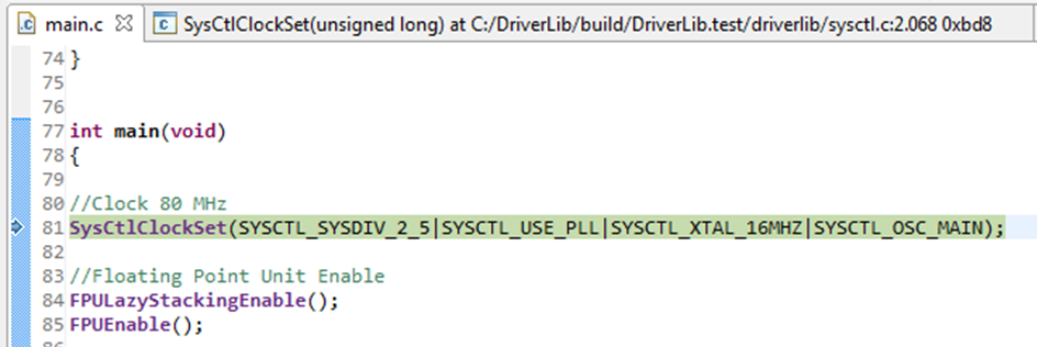
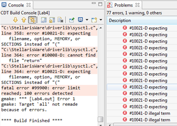
But second time, when supposed next step shoud jump to Line 84, the following error appears:

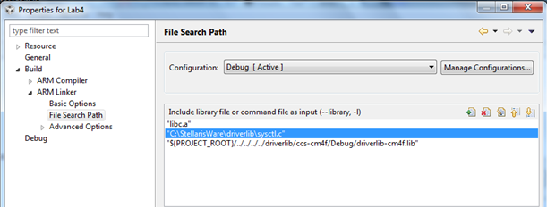
ARM Linker Path is correctly defined and also startup has the definition for ADC Int Handler properly. My code is shown below. Could you please say me if there is something wrong with it, that is causing error to prompt?. Thanks in advance

#include "inc/hw_ints.h"
#include "inc/hw_memmap.h"
#include "inc/hw_types.h"
#include "driverlib/sysctl.h"
#include "driverlib/interrupt.h"
#include "driverlib/gpio.h"
#include "driverlib/timer.h"
#include "driverlib/adc.h"
#include "driverlib/fpu.h"			//Floating Point Unit Support
#include <math.h>
#include "driverlib/pin_map.h"

#ifdef DEBUG
void__error__(char *pcFilename, unsigned long ulLine)
{
}
#endif


unsigned long uliSA[1];
unsigned long iSD;					//D-Stator Current
int SA,SB,SC, Sa, Sb, Sc;			//Inverter switching states
float Real_Comp,Im_Comp;			//Real & Imaginary components 
float Ud=108.04;					//Bus DC Voltage
float Rs=17.49;					//Stator Resistance
float T;							//Sample time
float FluxSD;						//D-Stator Flux
int WatchInt;

float Re_Table(int x, int y, int z){
	
	float Re;

		/*If else table is made to implement Real component  */

	if		(x==0 && y==0 && z==0) {Re=0;		}
	else if	(x==0 && y==0 && z==1) {Re=-0.5;	}
	else if	(x==0 && y==1 && z==0) {Re=-0.5;	}
	else if	(x==0 && y==1 && z==1) {Re=-1;		}
	else if	(x==1 && y==0 && z==0) {Re=1;		}
	else if	(x==1 && y==0 && z==1) {Re=0.5; 	}
	else if	(x==1 && y==1 && z==0) {Re=0.5;  	}
	else 						   {Re=0;		}

	return(Re);

}

float Im_Table(int x1, int y1, int z1){

	float Im;

		/*If else table is made to implement Imaginary component */

	if		(x1==0 && y1==0 && z1==0) {Im=0;				}
	else if	(x1==0 && y1==0 && z1==1) {Im=-((sqrt(3))/2);	}
	else if	(x1==0 && y1==1 && z1==0) {Im=((sqrt(3))/2);	}
	else if	(x1==0 && y1==1 && z1==1) {Im=0;				}
	else if	(x1==1 && y1==0 && z1==0) {Im=0;				}
	else if	(x1==1 && y1==0 && z1==1) {Im=-((sqrt(3))/2); 	}
	else if	(x1==1 && y1==1 && z1==0) {Im=((sqrt(3))/2);  	}
	else 						      {Im=0;				}


	return(Im);

}

float Flux_Est_D(float realc, float vbus, float rst, float st, unsigned long sdcurrent){
	//Pending flux k-1 term
	float fsd;
	fsd=((2/3)*vbus*st*realc)-rst*st*sdcurrent;
	return (fsd);
}


int main(void)
{

//Clock 80 MHz
SysCtlClockSet(SYSCTL_SYSDIV_2_5|SYSCTL_USE_PLL|SYSCTL_XTAL_16MHZ|SYSCTL_OSC_MAIN);

//Floating Point Unit Enable
FPULazyStackingEnable();
FPUEnable();

/*GPIO*/
SysCtlPeripheralEnable(SYSCTL_PERIPH_GPIOF);
GPIOPinTypeGPIOOutput(GPIO_PORTF_BASE, GPIO_PIN_1);

SysCtlPeripheralEnable(SYSCTL_PERIPH_GPIOE);
GPIOPinTypeGPIOInput(GPIO_PORTE_BASE, GPIO_PIN_1|GPIO_PIN_2|GPIO_PIN_3);
GPIOPadConfigSet(GPIO_PORTE_BASE, GPIO_PIN_1|GPIO_PIN_2|GPIO_PIN_3, GPIO_STRENGTH_2MA, GPIO_PIN_TYPE_STD_WPU);

/*Timer*/
//TimerConfigure(TIMER0_BASE, TIMER_CFG_32_BIT_PER);
SysCtlPeripheralEnable(SYSCTL_PERIPH_TIMER0);
TimerConfigure(TIMER0_BASE, TIMER_CFG_PERIODIC);
TimerLoadSet(TIMER0_BASE, TIMER_A, SysCtlClockGet() / 50000);//Timer timer couldn't be higher than sample rate
//Enable the timer’s ADC output trigger
TimerControlTrigger(TIMER0_BASE, TIMER_A, true);
// Enable the timer and start conversion process
// TimerIntEnable(TIMER0_BASE, TIMER_TIMA_TIMEOUT);
TimerEnable(TIMER0_BASE, TIMER_A);
// Enable ADC sequencer 0 and its interrupt (in both the ADC and NVIC)

/*ADC*/
SysCtlPeripheralEnable(SYSCTL_PERIPH_ADC0);	// ADC0 module enable
SysCtlADCSpeedSet(SYSCTL_ADCSPEED_1MSPS);	// 1.000.000 samples per second
ADCSequenceDisable(ADC0_BASE, 3);			//Disable ADC Sequencer 0
//Sequencer will be triggered by one of the general-purpose timers.
ADCSequenceConfigure(ADC0_BASE, 3, ADC_TRIGGER_TIMER, 0);
ADCSequenceStepConfigure(ADC0_BASE, 3, 0, ADC_CTL_CH6| ADC_CTL_IE | ADC_CTL_END);
ADCSequenceEnable(ADC0_BASE, 3);

IntMasterEnable();
ADCIntEnable(ADC0_BASE, 3);
IntEnable(INT_ADC0SS3);
//GPIOPinWrite(GPIO_PORTF_BASE, GPIO_PIN_1, 0);
WatchInt=0;


while(1){
Real_Comp=Re_Table(SA,SB,SC);
Im_Comp=Im_Table(SA,SB,SC);
FluxSD=Flux_Est_D(Real_Comp,Ud,Rs,T,iSD);
}

}


void ADC0IntHandler(void)
{

	WatchInt=1;
//Clear sample sequence interrupt source
ADCIntClear(ADC0_BASE, 3);
ADCSequenceDataGet(ADC0_BASE, 3, uliSA);
iSD=uliSA[0];
Sa = GPIOPinRead(GPIO_PORTE_BASE, GPIO_PIN_1);
Sb = GPIOPinRead(GPIO_PORTE_BASE, GPIO_PIN_2);
Sc = GPIOPinRead(GPIO_PORTE_BASE, GPIO_PIN_3);
//Positions 0, 1 and 2 are divided by 2, 4 and 8 respectively having so 0 or 1 values
SA=Sa/2.0;
SB=Sb/4.0;
SC=Sc/8.0;
}

  • Hello Diego,

    The forum has seen this issue quite a few times now. Normally what I do is to add the sysctl.c from the driverlib directory to allow for debug.

    Regards

    Amit

  • Hi,

        Add files sysctl.c at your project view under "Source". Build your project and try to step into SysCtlClockSet.

    - kel 

  • Hi Amit,

    When I clicket at locate file or also include it in Debug folder:

    Program continues debugging but enter into sysctl.c and starts jumping indefinitely between for and break and don´t gets out anymore:

    I am doing rigth?

    Thanks again.

  • Hi Markel,

    Do you refer to: rigth click on Project -  Properties - Build - ARM Linker - File Search Path?. If so, I did so:

    But program can't run given a lot of errors:

    Did you refer to ir or I did it wrong?

    Thank you.

  • Hello Diego,

    That is correct. Can you check if the SYSCTL_RIS register in the memory browser shows that the PLL is locked or not?

    Regards

    Amit

  • Hi dear Amit,

    I have checked SYSCTL_RIS:

    ulDelay begins to decrease according to for loop:

    And PLL isn't blocked (PLL Lock Raw Interrupt Status is 0):

    So, step into is working fine.

    But now I think I need to change my question for the task I need to performed from the beginning:

    How can I check if the program enter properly into ADC Int Handler? because when I test it, it seems that never jumps to ADC interrupt using step into and step over, as you can see in the enclosed video:

    0576.Step into Interrupt.rar

    Thanks for your kindly help!

  • Hello Diego

    The video was much helpful. Can you post your CCS project as well. I have a TM4C123 eval kit with me that I can use to check ASAP

    Regards

    Amit

  • Hi Amit,

    Of course. Enclosed you can find my whole project in .rar file. My Launchpad Board is EK-LM4F120XL.

    If you need something else, don´t hesitate in tell me.

    Thank you very much.

    3771.Lab4.rar

  • Hello Diego,

    I ran the test code on my TM4C123 evaluation kit (TM4C123 and LM4F120 are much alike) and it always goes to the Interrupt Handler provided the CPU Reset is done in the CCS window, instead of Code Restart.

    It may possibly be an artifact of a previous run.

    I also made some changes to the code, that I have attached.

    #include "inc/hw_ints.h"
    #include "inc/hw_memmap.h"
    #include "inc/hw_types.h"
    #include "driverlib/sysctl.h"
    #include "driverlib/interrupt.h"
    #include "driverlib/gpio.h"
    #include "driverlib/timer.h"
    #include "driverlib/adc.h"
    #include "driverlib/fpu.h"			//Floating Point Unit Support
    #include <math.h>
    #include "driverlib/pin_map.h"
    
    #ifdef DEBUG
    void__error__(char *pcFilename, unsigned long ulLine)
    {
    }
    #endif
    
    
    unsigned long uliSA[1];
    unsigned long iSD;					//D-Stator Current
    int SA,SB,SC, Sa, Sb, Sc;			//Inverter switching states
    float Real_Comp,Im_Comp;			//Real & Imaginary components for second member in 2.15 and 2.16 equations
    float Ud=108.04;					//Bus DC Voltage
    float Rs=17.49;						//Stator Resistance
    float T;							//Sample time
    float FluxSD;						//D-Stator Flux
    int WatchInt;
    
    float Re_Table(int x, int y, int z){
    	//A function can have zero or one output parameter. So, there is need for two functions: One for Re and other one for Im.
    	float Re;
    
    		/*If else table is made to implement Real component on equations 2.15 and 2.16 */
    
    	if		(x==0 && y==0 && z==0) {Re=0;		}
    	else if	(x==0 && y==0 && z==1) {Re=-0.5;	}
    	else if	(x==0 && y==1 && z==0) {Re=-0.5;	}
    	else if	(x==0 && y==1 && z==1) {Re=-1;		}
    	else if	(x==1 && y==0 && z==0) {Re=1;		}
    	else if	(x==1 && y==0 && z==1) {Re=0.5; 	}
    	else if	(x==1 && y==1 && z==0) {Re=0.5;  	}
    	else 						   {Re=0;		}
    
    	return(Re);
    
    }
    
    float Im_Table(int x1, int y1, int z1){
    
    	float Im;
    
    		/*If else table is made to implement Imaginary component on equations 2.15 and 2.16 */
    
    	if		(x1==0 && y1==0 && z1==0) {Im=0;				}
    	else if	(x1==0 && y1==0 && z1==1) {Im=-((sqrt(3))/2);	}
    	else if	(x1==0 && y1==1 && z1==0) {Im=((sqrt(3))/2);	}
    	else if	(x1==0 && y1==1 && z1==1) {Im=0;				}
    	else if	(x1==1 && y1==0 && z1==0) {Im=0;				}
    	else if	(x1==1 && y1==0 && z1==1) {Im=-((sqrt(3))/2); 	}
    	else if	(x1==1 && y1==1 && z1==0) {Im=((sqrt(3))/2);  	}
    	else 						      {Im=0;				}
    
    
    	return(Im);
    
    }
    
    float Flux_Est_D(float realc, float vbus, float rst, float st, unsigned long sdcurrent){
    	//Pending flux k-1 term
    	float fsd;
    	fsd=((2/3)*vbus*st*realc)-rst*st*sdcurrent;
    	return (fsd);
    }
    
    
    int main(void)
    {
    
    	//Clock 80 MHz
    	SysCtlClockSet(SYSCTL_SYSDIV_2_5|SYSCTL_USE_PLL|SYSCTL_XTAL_16MHZ|SYSCTL_OSC_MAIN);
    
    	//Floating Point Unit Enable
    	//FPULazyStackingEnable();
    	//FPUEnable();
    
    	/*GPIO*/
    	SysCtlPeripheralEnable(SYSCTL_PERIPH_GPIOF);
    	GPIOPinTypeGPIOOutput(GPIO_PORTF_BASE, GPIO_PIN_1);
    
    	SysCtlPeripheralEnable(SYSCTL_PERIPH_GPIOE);
    	GPIOPinTypeGPIOInput(GPIO_PORTE_BASE, GPIO_PIN_1|GPIO_PIN_2|GPIO_PIN_3);
    	GPIOPadConfigSet(GPIO_PORTE_BASE, GPIO_PIN_1|GPIO_PIN_2|GPIO_PIN_3, GPIO_STRENGTH_2MA, GPIO_PIN_TYPE_STD_WPU);
    
    	SysCtlPeripheralDisable(SYSCTL_PERIPH_ADC0);
    	SysCtlPeripheralReset(SYSCTL_PERIPH_ADC0);
    	SysCtlPeripheralReset(SYSCTL_PERIPH_TIMER0);
    
    	/*ADC*/
    	SysCtlPeripheralEnable(SYSCTL_PERIPH_ADC0);	// ADC0 module enable
    	SysCtlADCSpeedSet(SYSCTL_ADCSPEED_1MSPS);	// 1.000.000 samples per second
    	ADCSequenceDisable(ADC0_BASE, 3);			//Disable ADC Sequencer 0
    	//	Sequencer will be triggered by one of the general-purpose timers.
    	ADCSequenceConfigure(ADC0_BASE, 3, ADC_TRIGGER_TIMER, 0);
    	ADCSequenceStepConfigure(ADC0_BASE, 3, 0, ADC_CTL_CH6| ADC_CTL_IE | ADC_CTL_END);
    	ADCSequenceEnable(ADC0_BASE, 3);
    
    	/*Timer*/
    	//TimerConfigure(TIMER0_BASE, TIMER_CFG_32_BIT_PER);
    	SysCtlPeripheralEnable(SYSCTL_PERIPH_TIMER0);
    	TimerConfigure(TIMER0_BASE, TIMER_CFG_PERIODIC);
    	TimerLoadSet(TIMER0_BASE, TIMER_A, SysCtlClockGet() / 50000);//Timer timer couldn't be higher than sample rate
    	//Enable the timer�s ADC output trigger
    	TimerControlTrigger(TIMER0_BASE, TIMER_A, true);
    	// Enable the timer and start conversion process
    	// TimerIntEnable(TIMER0_BASE, TIMER_TIMA_TIMEOUT);
    	TimerEnable(TIMER0_BASE, TIMER_A);
    	// Enable ADC sequencer 0 and its interrupt (in both the ADC and NVIC)
    
    	ADCIntEnable(ADC0_BASE, 3);
    	IntEnable(INT_ADC0SS3);
    	IntMasterEnable();
    	//GPIOPinWrite(GPIO_PORTF_BASE, GPIO_PIN_1, 0);
    	WatchInt=0;
    
    	while(1)
    	{
    		Real_Comp=Re_Table(SA,SB,SC);
    		Im_Comp=Im_Table(SA,SB,SC);
    		FluxSD=Flux_Est_D(Real_Comp,Ud,Rs,T,iSD);
    	}
    
    }
    
    
    void ADC0IntHandler(void)
    {
    	WatchInt=1;
    	//Clear sample sequence interrupt source
    	ADCIntClear(ADC0_BASE, 3);
    	ADCSequenceDataGet(ADC0_BASE, 3, uliSA);
    	iSD=uliSA[0];
    	Sa = GPIOPinRead(GPIO_PORTE_BASE, GPIO_PIN_1);
    	Sb = GPIOPinRead(GPIO_PORTE_BASE, GPIO_PIN_2);
    	Sc = GPIOPinRead(GPIO_PORTE_BASE, GPIO_PIN_3);
    	//Positions 0, 1 and 2 are divided by 2, 4 and 8 respectively having so 0 or 1 values
    	SA=Sa/2.0;
    	SB=Sb/4.0;
    	SC=Sc/8.0;
    }
    

    Also please note that in the code I did not see any pad being set to ADC Function...

    Regards

    Amit

  • Hello Amit,

    I tested the code again with the reset commands you include last time. Only enable floating point unit again. 

    It seems that program works properly because variables inside ADC0IntHandler are updated in Expressions tab when execution reaches IntMasterEnable instruction just at line 125. But why step never jumps to ADC0IntHandler? Following a brief video in which program flow can be seen better:

    1106.ADC Int Handler.rar

    Program is working well now? This jump after IntMasterEnable is only related with global interruptions or also with ADC0IntHandler?

    PD: I wrote my project over Lab4 folder from StellarisWare to include everything in it (startup, etc). Would be any problem with it?

    Thanks again for your time and help.

    Warm regards,

    Diego

  • Hello Diego

    That should not be a problem

    Regards

    Amit

  • Hi Amit,

    OK, Thanks for all your help!

    Regards,

    Diego