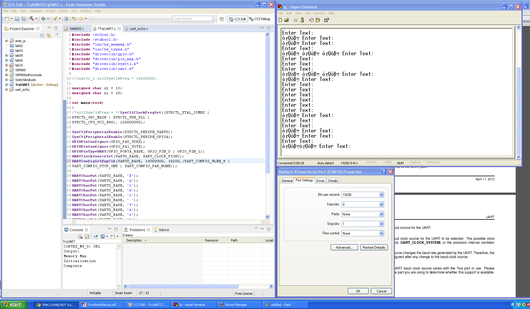
hi, I can get 115200 and 57600 baud rates to work without errors but not with slower rates. I need 19200 to use a SIM900 module. Here is a screen shot: 
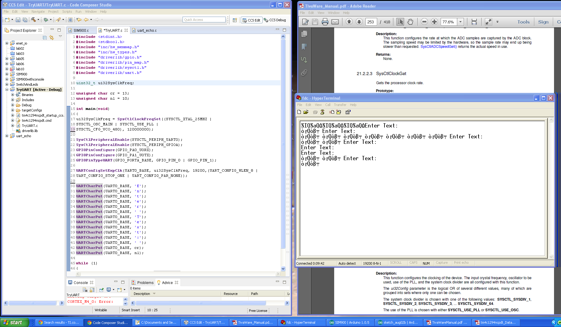
any help would be great. thanks, dan
This thread has been locked.
If you have a related question, please click the "Ask a related question" button in the top right corner. The newly created question will be automatically linked to this question.
yep, i did the same for 9600, 19200, 38400, 57600, and 115200. only the higher ones work. the only code that i'm changing is in UARTConfigSetExpClk() . " Enter Text: " is the only thing that should be there.
Hi Daniel,
I think this is related to the Error rate. AFAIK, something like higher system clock with lower baud rate will have higher error rate. Correct me if I am wrong.
I see you set the system clock at 120MHz and it only works for 115200 and 57600 baud rate. So, try a lower system clock for 19200 baud rate.
You, can experiment and start from 16MHz, 25MHz, 50Mhz, then 80Mhz system clock. There are other system clock settings, these are the ones that I currently remember.
- kel
Hello Daniel,
Sometimes I have noticed similar behavior with TeraTerm and the first thing to do is check the Baud Rate in the Device Manager, followed by close and reopen of the Terminal Applications.
The second thing to do is to switch the UART Clock to PIOSC using UARTClockSourceSet and then in UARTConfigSetExpClk use 16000000 as the clock frequency.
Regards
Amit
Hello Daniel,
Can you download teraterm (though it should not matter) and use this application instead of Hyper Terminal.
Since the pattern you are sending is the same, so it would be more or less the same errors coming on the terminal console
Regards
Amit
hey,
I downloaded and installed teraterm. I'm getting the same number of errors as HyperTerminal at 9600 and 19200. just as you thought. Changing the clock source did get 38400 to work without errors. getting closer.
Feel your pain - and wondrous, "Does not work" sits squarely - this time - upon this MCU's shoulders.
Beg/borrow a scope - repeated transmission of 0x55 and then 0xAA yields an easily recognized, "0-1" or "1-0" repeated bit pattern. This eases the measurement of the individual bit timing. Recall that 9600 baud yields ~104uS bit timing - even a crude/old scope should be able to display that. Your 19K2 baud halves that bit duration.
Feeding your measurement results back here should enable Amit's, "inside info store" to better diagnose... Start w/Amit's suggestion of internal osc - but you may wish to identify your external xtal freq. - and provide measurement results (neatly charted) for various baud rates there - as well.
And - check (double check) that there are no unexpected/unwanted "mystery" connections intruding upon either UART signal line.
As always - we're not told if you're employing RS232 and a level shifter is in play. (though - working @ higher baud rates - tends to dismiss them as error causes...)
Should state that our past stable of, "EOL" M3s and LX4Fs performed flawlessly - across your entire/desired baud range. Progress! (Oi...)
[edit] Just reread your opening - screen shot suggests that the msbit is set - which seems not your desire. (normal ASCII extends to 127 decimal (0x7F) for "displayable characters." Such is a clear indicator of a, "Timing error." Scope very much required unless MCU errata has noted/worked around...
looking at the data sheet for the SIM900 GMS module I plan on using. There is a autobauding feature and the default baud rates is 115200. So, maybe The slower baud rates working may not matter.
This problem should be easy to reproduce. I started this project with the instructions here: http://software-dl.ti.com/trainingTTO/trainingTTO_public_sw/Tiva_CLP/CLP_Workbook.pdf starting at " ► Right-click on lab02 in the Project Explorer pane" in the middle of page 50. follow them to page 53. then add part to
I cleaned up the code a little bit from the original. This code works at this baud rate but, changing lowering below 38400 breaks it. I started with the UART example code from the workbook linked above.
#include <stdint.h>
#include <stdbool.h>
#include "inc/hw_memmap.h"
#include "inc/hw_types.h"
#include "driverlib/gpio.h"
#include "driverlib/pin_map.h"
#include "driverlib/sysctl.h"
#include "driverlib/uart.h"
unsigned char CReturn = 13; //carrage return
unsigned char NLine = 10; //new line
unsigned char buffer1[15] = "ENTER TEXT: ";
unsigned char i = 0;
int main(void)
{
SysCtlClockFreqSet((SYSCTL_XTAL_25MHZ |
SYSCTL_OSC_MAIN | SYSCTL_USE_PLL |
SYSCTL_CFG_VCO_480), 120000000);
SysCtlPeripheralEnable(SYSCTL_PERIPH_UART0);
SysCtlPeripheralEnable(SYSCTL_PERIPH_GPIOA);
GPIOPinConfigure(GPIO_PA0_U0RX);
GPIOPinConfigure(GPIO_PA1_U0TX);
GPIOPinTypeUART(GPIO_PORTA_BASE, GPIO_PIN_0 | GPIO_PIN_1);
UARTClockSourceSet(UART0_BASE, UART_CLOCK_PIOSC);
UARTConfigSetExpClk(UART0_BASE, 16000000, 115200,(UART_CONFIG_WLEN_8 |
UART_CONFIG_STOP_ONE | UART_CONFIG_PAR_NONE));
while(buffer1[i] != '\0'){
UARTCharPut(UART0_BASE, buffer1[i]);
i++;
}
i = 0;
UARTCharPut(UART0_BASE, CReturn );
UARTCharPut(UART0_BASE, NLine);
while (1)
{
if (UARTCharsAvail(UART0_BASE)) UARTCharPut(UART0_BASE, UARTCharGet(UART0_BASE));
}
}
I'd like to help if possible but, don't have a scope at the moment.
daniel preston said:SysCtlClockFreqSet((SYSCTL_XTAL_25MHZ |
SYSCTL_OSC_MAIN | SYSCTL_USE_PLL |
SYSCTL_CFG_VCO_480), 120000000);SysCtlPeripheralEnable(SYSCTL_PERIPH_UART0);
SysCtlPeripheralEnable(SYSCTL_PERIPH_GPIOA);
GPIOPinConfigure(GPIO_PA0_U0RX);
GPIOPinConfigure(GPIO_PA1_U0TX);
GPIOPinTypeUART(GPIO_PORTA_BASE, GPIO_PIN_0 | GPIO_PIN_1);
UARTClockSourceSet(UART0_BASE, UART_CLOCK_PIOSC);
UARTConfigSetExpClk(UART0_BASE, 16000000, 115200,(UART_CONFIG_WLEN_8 |
UART_CONFIG_STOP_ONE | UART_CONFIG_PAR_NONE));
I don't think that is correct.
If your system clock is 120Mhz, your UART clock source value should also be 120MHz. .
If you want the UART clock source to be 16MHz, then your system clock source should be 16Mhz. But, since your Main OSC value is 25Mhz, I don't think it is possible to set the system clock at 16Mhz. I will try to help you later with my Tiva Connected launchpad.
- kel
Markel Robregado said:want the UART clock source to be 16MHz, then your system clock source should be 16Mhz. But, since your Main OSC value is 25Mhz, I don't think it is possible to set the system clock at 16Mhz.
Sure it is - and few posts up - Amit described just how!
Amit, "Switch the UART Clock to PIOSC using UARTClockSourceSet and then in UARTConfigSetExpClk use 16000000 as the clock frequency."
I cannot tell if poster followed that direction - and appears to avoid mine (use a scope) as well. (cb1 departs)
the uart isn't using the main clock. it's using the precision internal oscillator.
UARTClockSourceSet(UART0_BASE, UART_CLOCK_PIOSC);
daniel preston said:the uart isn't using the main clock. it's using the precision internal oscillator.
UARTClockSourceSet(UART0_BASE, UART_CLOCK_PIOSC);
I just woke up so . . . . . my mistake . . . . . .
- kel
daniel preston said:it's using the precision internal oscillator.
One hopes that's the case. You were not clear (at least to me) if you followed Amit's "2 part" instruction. (I repeated it - one cb1 post - up.
We assume that a scope is not available?
Hi All,
I have confirmed that 19200 UART Baud Rate works with lower UART Clock Source Value. Also, even if you set the UART clock source as PIOSC 16Mhz, if System Clock is high there will be garbled output. The higher the System Clock with low UART Baud rate settings, The higher rate of garble data outputs
I use the uart_echo example program with this system clock setup and uart clock setup below. I test the output at TeraTerm at each system clock setting at 120Mhz, 60Mhz, 48Mhz, 30Mhz, 24Mhz, 12Mhz and 6 Mhz. I reset the board repeatedly to see if any garbled data would output at TeraTerm.
g_ui32SysClock = MAP_SysCtlClockFreqSet((SYSCTL_XTAL_25MHZ |
SYSCTL_OSC_MAIN |
SYSCTL_USE_PLL |
SYSCTL_CFG_VCO_480), 48000000);
ROM_UARTConfigSetExpClk(UART0_BASE, g_ui32SysClock, 19200,
(UART_CONFIG_WLEN_8 | UART_CONFIG_STOP_ONE |
UART_CONFIG_PAR_NONE));
At 120Mhz, 60Mhz, 48Mhz TeraTerm output (Garbled):
At 30Mhz, 24Mhz, 12Mhz, 6Mhz Tera Term Ouput (No Garble);
- kel
Thanks everyone, been a lot of help. I have a GPRS Arduino shield with a SIM900 sending text messages. I worried over the 19200 baud for no reason. The default baud speed for the SIM900 is 115200. I just had to read the data sheet.
@Kel,
I liked your last post - great effort/detail and "free" from that (so long) signature block appeal... (that "blurb" does make even a one sentence post appear bit more considered...)
Appears you/I/others may have different sense of, "Garbled." Your top screen cap shows, "Testing Baud" generated nicely - but then "followed" by 5 (we assume) errant or phantom characters. I would not classify that as, "Garbled" instead it appears to be unexpected/unwanted "extra" transmission.
Believe, "Garbled" to be generally agreed to be, "those characters arriving w/no apparent, recognizable consistency." As your first 12 chars. arrived fine - "garbled" appears not to be the best descriptor...
If one had to guess - some, "buffer management" issue would rise on my, "suspect list."
when it works after resetting the launchpad it saids "enter text: " in the HyperTerminal . when it's doesn't you get the garbage. all the garbage and the text are from repeated resets and not extra transmissions. i displayed it that way to show sometimes it works and others not.
@Daniel,
Yes that was the response. I just change the "Enter Text", during my testing.
Just to detail, at 60Mhz system clock and 19200 baud rate, these are the exact output response
After board reset: "Testing Baud"
After board reset: "garbled output"
After board reset: "Testing Baud"
After board reset: "garbled output"
The picture I post here with garbled data is exact output.
At 120 Mhz system clock and UART clock set to PIOSC and 19200 baud rate
After board reset: "garbled output"
- kel