Other Parts Discussed in Thread: ENERGIA
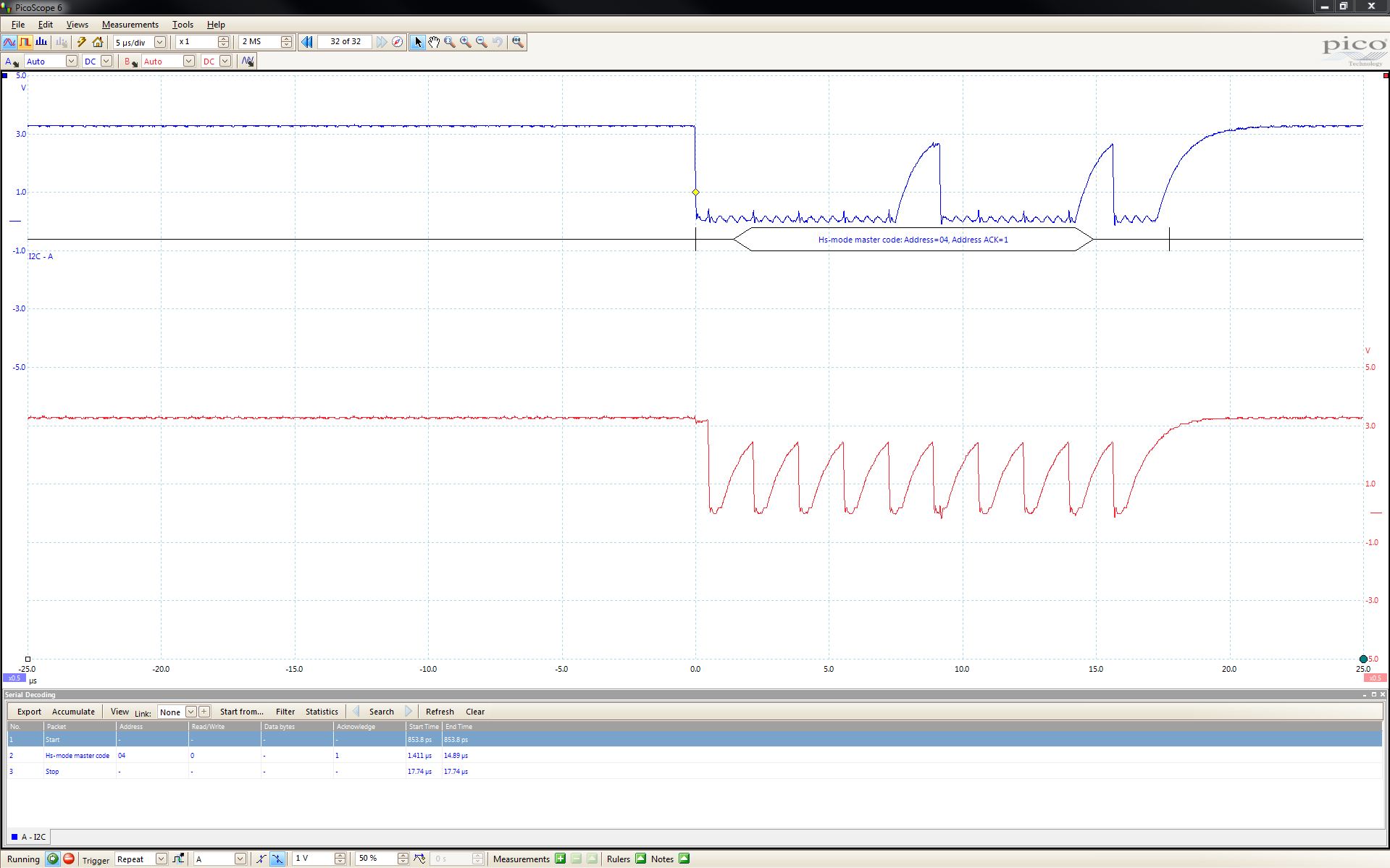
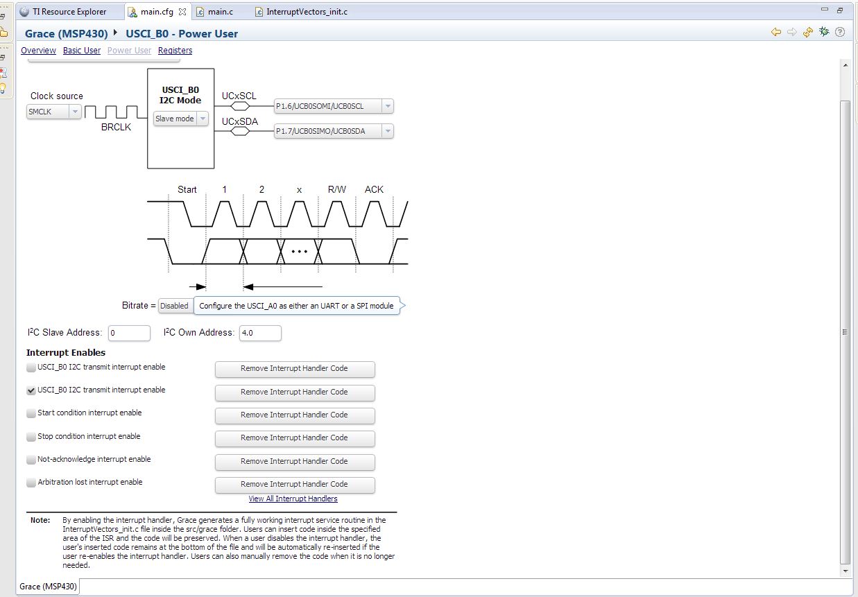
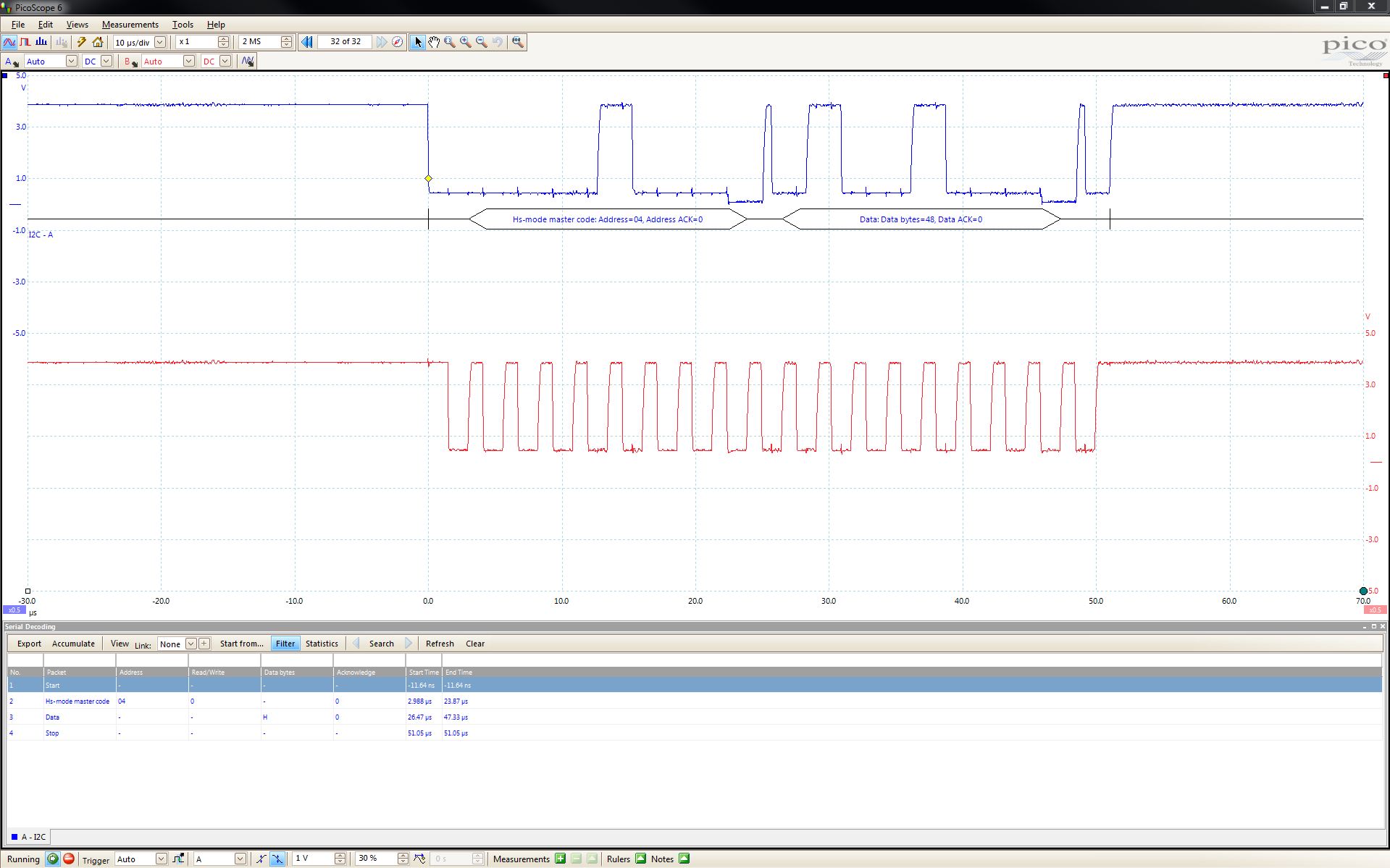
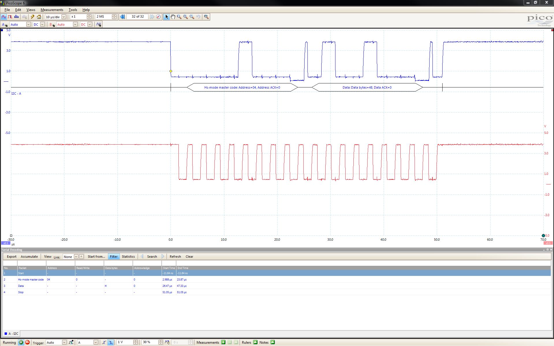
I am having trouble with setting up i2c with the TM4C1294 as the master sender and the MSP430 G2553 as the slave reciever. The master seems to only be sending the address (Scope.jpg). The master_TX.txt file is the code for the TM4C1294 and the slave_RX_Configuration.jpg is a screen shot of the Grace i2c configuration for the slave recieve and the slave_RX.txt is a copy of the InterruptVectors_init.c for the MSP430 g2553. What am I doing wrong? [[View:http://e2e.ti.com/cfs-file.ashx/__key/communityserver-discussions-components-files/908/2705.master_5F00_TX.txt]
/*
 *  This file is automatically generated and does not require a license
 *
 *  ==== WARNING: CHANGES TO THIS GENERATED FILE WILL BE OVERWRITTEN ====
 *
 *  To make changes to the generated code, use the space between existing
 *      "USER CODE START (section: <name>)"
 *  and
 *      "USER CODE END (section: <name>)"
 *  comments, where <name> is a single word identifying the section.
 *  Only these sections will be preserved.
 *
 *  Do not move these sections within this file or change the START and
 *  END comments in any way.
 *  ==== ALL OTHER CHANGES WILL BE OVERWRITTEN WHEN IT IS REGENERATED ====
 *
 *  This file was generated from
 *      C:/ti/grace_3_00_01_59/packages/ti/mcu/msp430/csl/interrupt_vectors/InterruptVectors_init.xdt
 */
#include <msp430.h>

/* USER CODE START (section: InterruptVectors_init_c_prologue) */
/* User defined includes, defines, global variables and functions */
/* USER CODE END (section: InterruptVectors_init_c_prologue) */

/*
 *  ======== InterruptVectors_graceInit ========
 */
void InterruptVectors_graceInit(void)
{
}


/* Interrupt Function Prototypes */


/*
 *  ======== USCI A0/B0 TX Interrupt Handler Generation ========
 *
 * Here are several important notes on using USCI_A0/B0 TX interrupt Handler:
 * 1. User could use the following code as a template to service the interrupt
 *    handler. Just simply copy and paste it into your user definable code
 *    section.
 *  For UART and SPI configuration:

    if (IFG2 & UCA0TXIFG) {

    }
    else if (IFG2 & UCB0TXIFG) {

    }

 *  For I2C configuration:
    if (IFG2 & UCA0/B0TXIFG) {

    }
    else if (IFG2 & UCA0/B0RXIFG) {

    }


 * 2. User could also exit from low power mode and continue with main
 *    program execution by using the following instruction before exiting
 *    this interrupt handler.
 *
 *    __bic_SR_register_on_exit(LPMx_bits);
 */
#pragma vector=USCIAB0TX_VECTOR
__interrupt void USCI0TX_ISR_HOOK(void)
{
    /* USER CODE START (section: USCI0TX_ISR_HOOK) */
    /* replace this comment with your code */
    /* USER CODE END (section: USCI0TX_ISR_HOOK) */
}

/*
 *  ======== USCI A0/B0 RX Interrupt Handler Generation ========
 *
 * Here are several important notes on using USCI_A0/B0 RX interrupt Handler:
 * 1. User could use the following code as a template to service the interrupt
 *    handler. Just simply copy and paste it into your user definable code
 *    section.
 *  For UART and SPI configuration:

    if (IFG2 & UCA0RXIFG) {

    }
    else if (IFG2 & UCB0RXIFG) {

    }

*  For I2C configuration:
    if (UCB0STAT & UCSTTIFG) {

    }
    else if (UCB0STAT & UCSTPIFG) {

    }
    else if (UCB0STAT & UCNACKIFG) {

    }
    else if (UCB0STAT & UCALIFG) {

    }

 * 2. User could also exit from low power mode and continue with main
 *    program execution by using the following instruction before exiting
 *    this interrupt handler.
 *
 *    __bic_SR_register_on_exit(LPMx_bits);
 */
#pragma vector=USCIAB0RX_VECTOR
__interrupt void USCI0RX_ISR_HOOK(void)
{
	char data = 0;
	data = UCB0RXBUF;
}