This thread has been locked.

If you have a related question, please click the "Ask a related question" button in the top right corner. The newly created question will be automatically linked to this question.

TM4C123G PWM 80 MHz

Other Parts Discussed in Thread: EK-TM4C123GXL

Hii all,

When I am using 80MHz clock , my pwm signal at 1 MHz is distorted. while at system frequency of 40 MHz , it is quite accurate. why??

  • Hello Prashant,

    It would be more useful if you have the code posted as well what "distorted" looks like and clean signal looks like?

    Regards

    Amit

  • #include <stdint.h>
    #include <stdbool.h>
    #include "inc/hw_gpio.h"
    #include "inc/hw_types.h"
    #include "inc/hw_memmap.h"
    #include "driverlib/sysctl.h"
    #include "driverlib/pin_map.h"
    #include "driverlib/gpio.h"
    #include "driverlib/pwm.h"

    int
    main(void)
    { unsigned long ulPeriod;

    //Set the clock
    SysCtlClockSet(SYSCTL_SYSDIV_1 | SYSCTL_USE_OSC | SYSCTL_OSC_MAIN | SYSCTL_XTAL_16MHZ); //for 40 MHz
    // SysCtlClockSet(SYSCTL_SYSDIV_1 | SYSCTL_USE_OSC | SYSCTL_OSC_MAIN | SYSCTL_XTAL_16MHZ); //for 80MHz

    //Configure PWM Clock to match system
    SysCtlPWMClockSet(SYSCTL_PWMDIV_1);

    // Enable the peripherals used by this program.
    SysCtlPeripheralEnable(SYSCTL_PERIPH_GPIOF);
    SysCtlPeripheralEnable(SYSCTL_PERIPH_PWM1); //The Tiva Launchpad has two modules (0 and 1). Module 1 covers the LED pins
    ulPeriod = SysCtlClockGet() / 1000000; //PWM frequency

    //Configure PF1,PF2,PF3 Pins as PWM

    GPIOPinConfigure(GPIO_PF1_M1PWM5);
    GPIOPinConfigure(GPIO_PF2_M1PWM6);
    GPIOPinConfigure(GPIO_PF3_M1PWM7);
    GPIOPinTypePWM(GPIO_PORTF_BASE, GPIO_PIN_1 | GPIO_PIN_2 | GPIO_PIN_3);

    //Configure PWM Options
    //PWM_GEN_2 Covers M1PWM4 and M1PWM5
    //PWM_GEN_3 Covers M1PWM6 and M1PWM7 See page 207 4/11/13 DriverLib doc
    PWMGenConfigure(PWM1_BASE, PWM_GEN_2, PWM_GEN_MODE_UP_DOWN | PWM_GEN_MODE_NO_SYNC);
    PWMGenConfigure(PWM1_BASE, PWM_GEN_3, PWM_GEN_MODE_UP_DOWN | PWM_GEN_MODE_NO_SYNC);

    //Set the Period (expressed in clock ticks)
    PWMGenPeriodSet(PWM1_BASE, PWM_GEN_2, ulPeriod);
    PWMGenPeriodSet(PWM1_BASE, PWM_GEN_3, ulPeriod);

    //Set PWM duty-50% (Period /2)
    PWMPulseWidthSet(PWM1_BASE, PWM_OUT_5,ulPeriod/(100/30));
    PWMPulseWidthSet(PWM1_BASE, PWM_OUT_6,ulPeriod/2);
    PWMPulseWidthSet(PWM1_BASE, PWM_OUT_7,ulPeriod/2);

    // Enable the PWM generator
    PWMGenEnable(PWM1_BASE, PWM_GEN_2);
    PWMGenEnable(PWM1_BASE, PWM_GEN_3);

    // Turn on the Output pins
    PWMOutputState(PWM1_BASE, PWM_OUT_5_BIT |PWM_OUT_6_BIT|PWM_OUT_7_BIT, true);

    //Do nothing
    while(1)
    {

    }

    }

    ////////////////////////////////////////////////////////////////////////////////////////////////////////////////////////////////////////////////////////////

    for 80 MHz system clock and 1MHz PWM , output waveform is of 1.33 MHz

    But for 40MHz system clock and 1MHz PWM , output waveform is of 1MHz accurate. 

  • Hello Prashant,

    First of all there is a coding error. You have mentioned the clock set function as following

    SysCtlClockSet(SYSCTL_SYSDIV_1 | SYSCTL_USE_OSC | SYSCTL_OSC_MAIN | SYSCTL_XTAL_16MHZ); //for 40 MHz
    // SysCtlClockSet(SYSCTL_SYSDIV_1 | SYSCTL_USE_OSC | SYSCTL_OSC_MAIN | SYSCTL_XTAL_16MHZ); //for 80MHz

    When the System Clock is Main Oscillator you cannot get 80MHz or anything above 16Mhz for that matter.

    Secondly, If you are using TIVAWare 2.1.0 then there is a known bug that for 80Mhz the API SysCtlClockGet function will return 66MHz. Instead of using the API return value, you would need to hardcode the value for 80000000.

    Regards

    Amit

  • hiii amit

    thank you. so how can i use 80 MHz clock? 

  • Hello Prashant,

    To get 80MHz clock you would need to use the API as

    SysCtlClockSet(SYSCTL_SYSDIV_2_5 | SYSCTL_USE_PLL| SYSCTL_OSC_MAIN | SYSCTL_XTAL_16MHZ);

    And instead of using the return value of SysCtlClockGet use the fixed value of 80000000 assigned to the variable that was previously getting the value from the SysCtlClockGet API

    Regards

    Amit

  • hii amit

    I am using this.

    SysCtlClockSet(SYSCTL_SYSDIV_2_5 | SYSCTL_USE_PLL| SYSCTL_OSC_MAIN | SYSCTL_XTAL_16MHZ);

    instead of

    ulPeriod = SysCtlClockGet() / 1000000;

    i am using

    ulPeriod = 80000000/ 1000000;

    but still i am not able to get 80MHz clock.

    Regards

    Prashant

  • Hello Prashant

    Is the crystal you are using 16MHz? And you are measuring the 80MHz by looking at the PWM output?

    Regards

    Amit

  • hii amit.

    yes i am using 16 MHz crystal. I am not measuring 80 MHz. I am seeing quality of PWM output. at 80 MHz should be better than that of pwm at 16 MHz.

  • Hello Prashant,

    I can try this on my EK-TM4C123GXL LaunchPad. Will post reply after testing.

    Regards

    Amit

  • hii amit

    thank you. will be waiting.

    Regards

    Prashant

  • Hello Prashant,

    I took the code you had

        unsigned long ulPeriod;

        //Set the clock
        SysCtlClockSet(SYSCTL_SYSDIV_2_5 | SYSCTL_USE_PLL | SYSCTL_OSC_MAIN | SYSCTL_XTAL_16MHZ); //for 80 MHz

        //Configure PWM Clock to match system
        SysCtlPWMClockSet(SYSCTL_PWMDIV_1);

        // Enable the peripherals used by this program.
        SysCtlPeripheralEnable(SYSCTL_PERIPH_GPIOF);
        SysCtlPeripheralEnable(SYSCTL_PERIPH_PWM1); //The Tiva Launchpad has two modules (0 and 1). Module 1 covers the LED pins
        ulPeriod = 80000000 / 1000000; // PWM frequency

        //Configure PF1,PF2,PF3 Pins as PWM

        GPIOPinConfigure(GPIO_PF1_M1PWM5);
        GPIOPinConfigure(GPIO_PF2_M1PWM6);
        GPIOPinConfigure(GPIO_PF3_M1PWM7);
        GPIOPinTypePWM(GPIO_PORTF_BASE, GPIO_PIN_1 | GPIO_PIN_2 | GPIO_PIN_3);

        //Configure PWM Options
        //PWM_GEN_2 Covers M1PWM4 and M1PWM5
        //PWM_GEN_3 Covers M1PWM6 and M1PWM7 See page 207 4/11/13 DriverLib doc
        PWMGenConfigure(PWM1_BASE, PWM_GEN_2, PWM_GEN_MODE_UP_DOWN | PWM_GEN_MODE_NO_SYNC);
        PWMGenConfigure(PWM1_BASE, PWM_GEN_3, PWM_GEN_MODE_UP_DOWN | PWM_GEN_MODE_NO_SYNC);

        //Set the Period (expressed in clock ticks)
        PWMGenPeriodSet(PWM1_BASE, PWM_GEN_2, ulPeriod);
        PWMGenPeriodSet(PWM1_BASE, PWM_GEN_3, ulPeriod);

        //Set PWM duty-50% (Period /2)
        PWMPulseWidthSet(PWM1_BASE, PWM_OUT_5,ulPeriod/(100/30));
        PWMPulseWidthSet(PWM1_BASE, PWM_OUT_6,ulPeriod/2);
        PWMPulseWidthSet(PWM1_BASE, PWM_OUT_7,ulPeriod/2);

        // Enable the PWM generator
        PWMGenEnable(PWM1_BASE, PWM_GEN_2);
        PWMGenEnable(PWM1_BASE, PWM_GEN_3);

        // Turn on the Output pins
        PWMOutputState(PWM1_BASE, PWM_OUT_5_BIT |PWM_OUT_6_BIT|PWM_OUT_7_BIT, true);

        //Do nothing
        while(1)
        {

        }

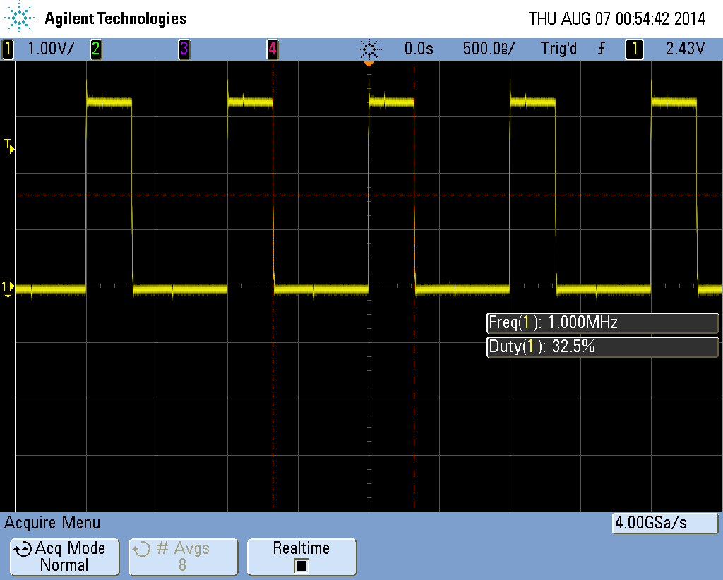
    And ran it. Attached is the output of PF1. It is a 1MHz 32.5% DC output

    Regards

    Amit