This thread has been locked.

If you have a related question, please click the "Ask a related question" button in the top right corner. The newly created question will be automatically linked to this question.

TM4C1294 Controller Area Network Set-up

Other Parts Discussed in Thread: SN65HVD1050, LMFLASHPROGRAMMER, EK-TM4C1294XL

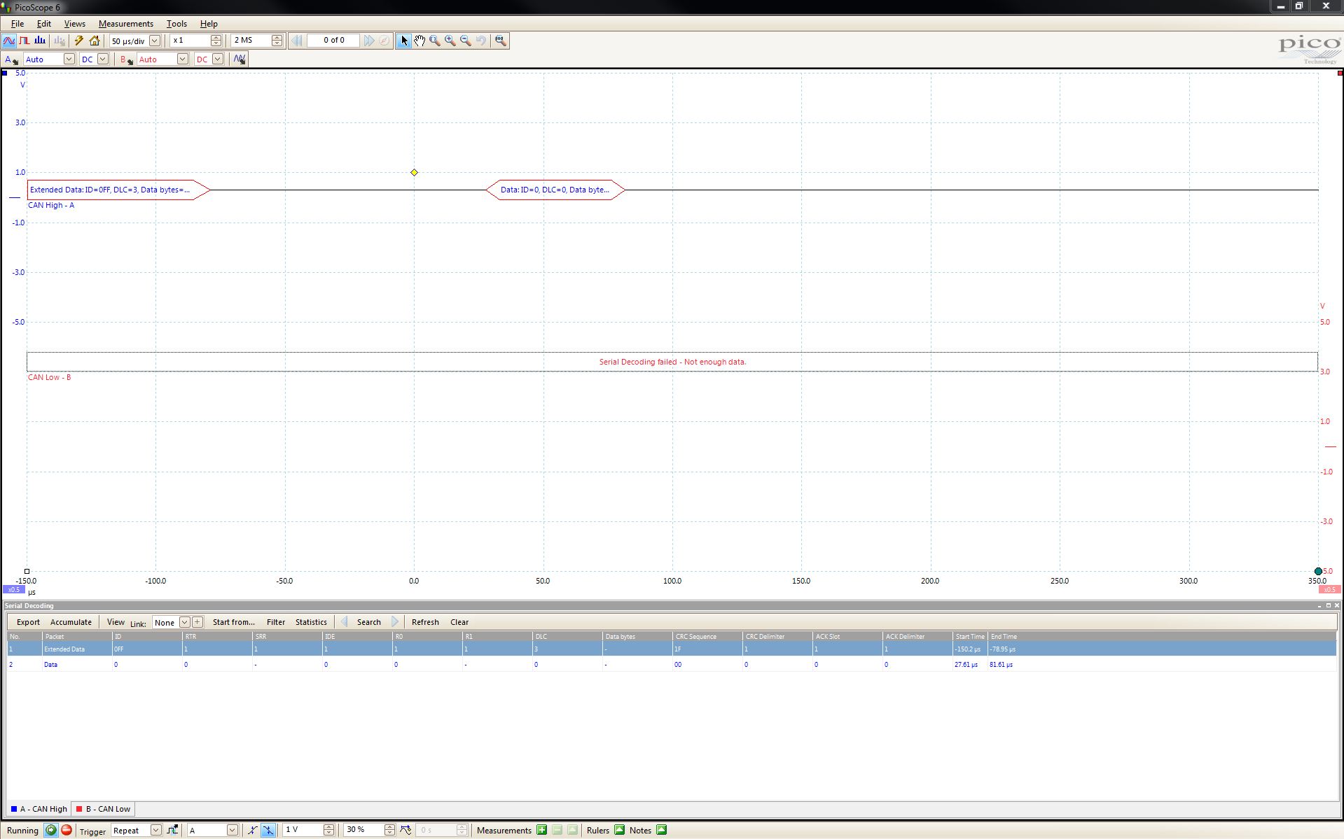
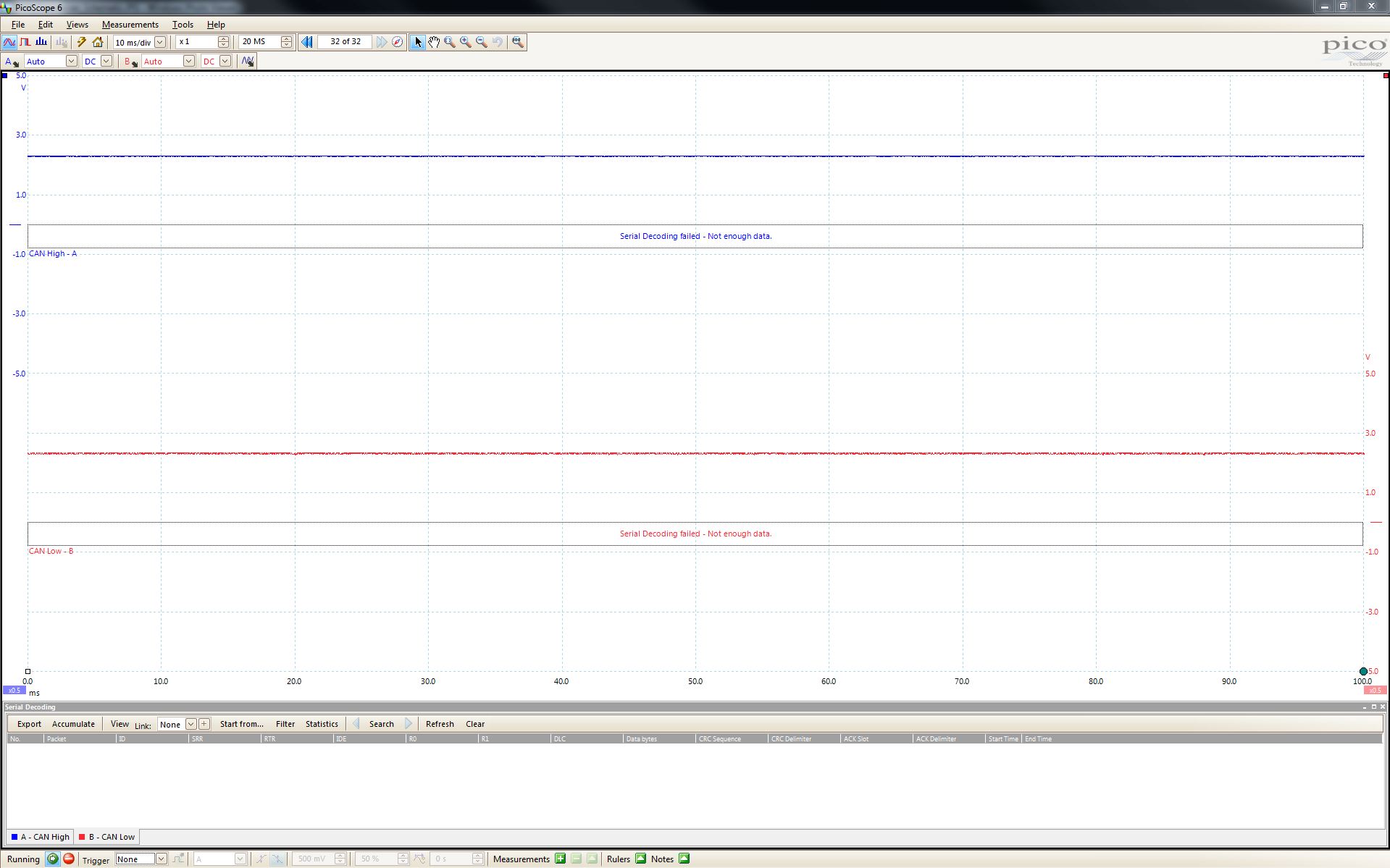
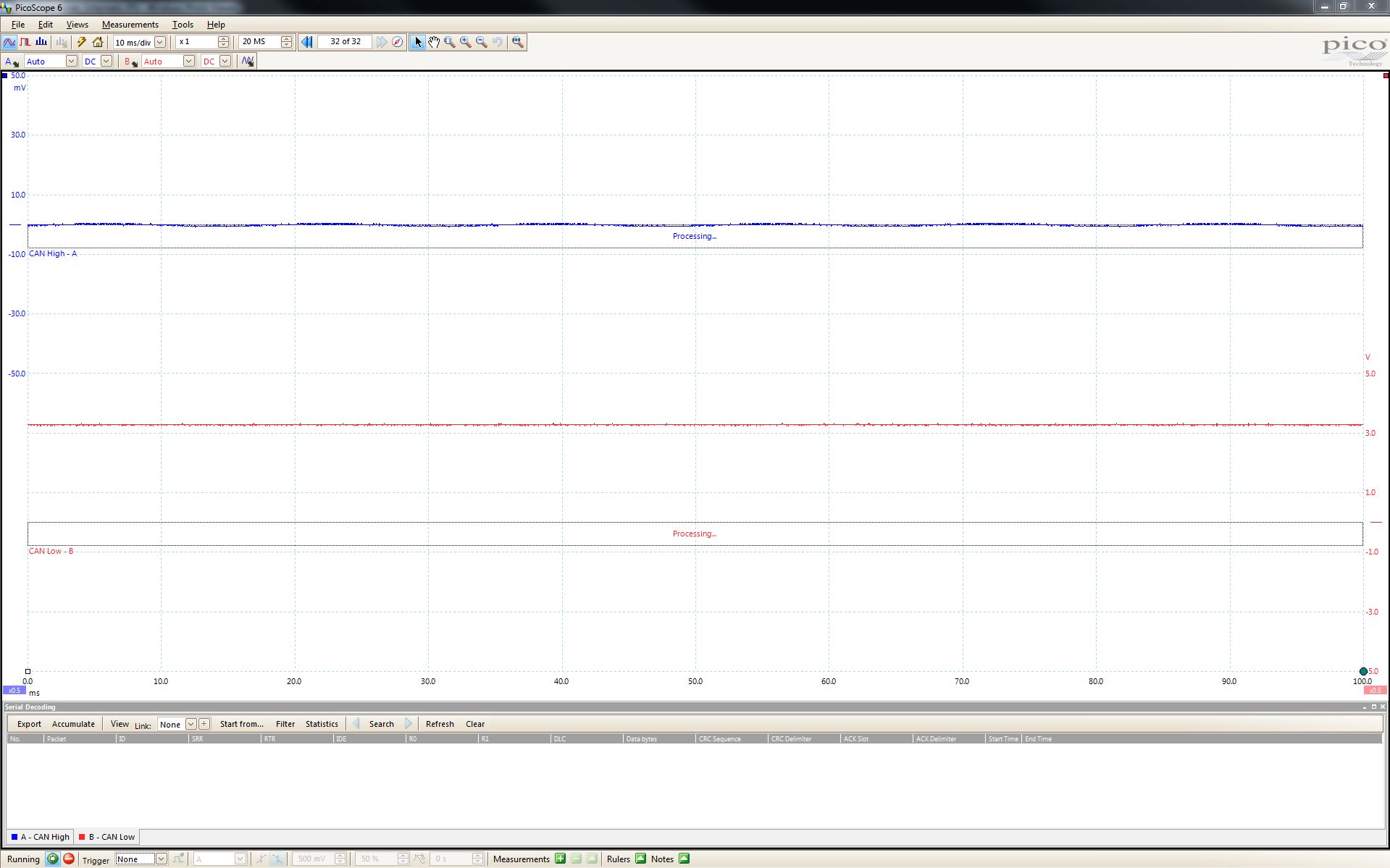
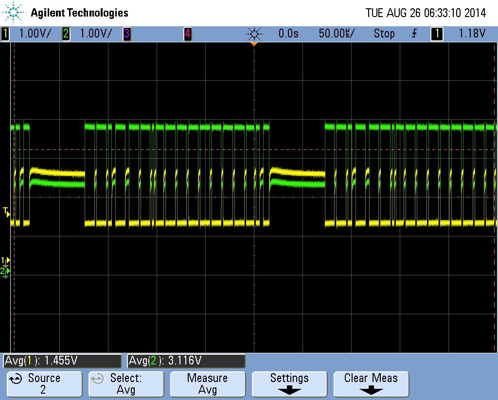
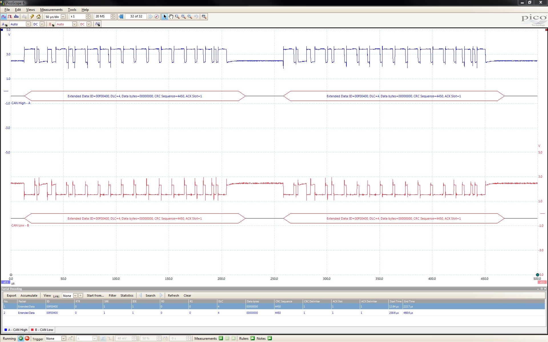
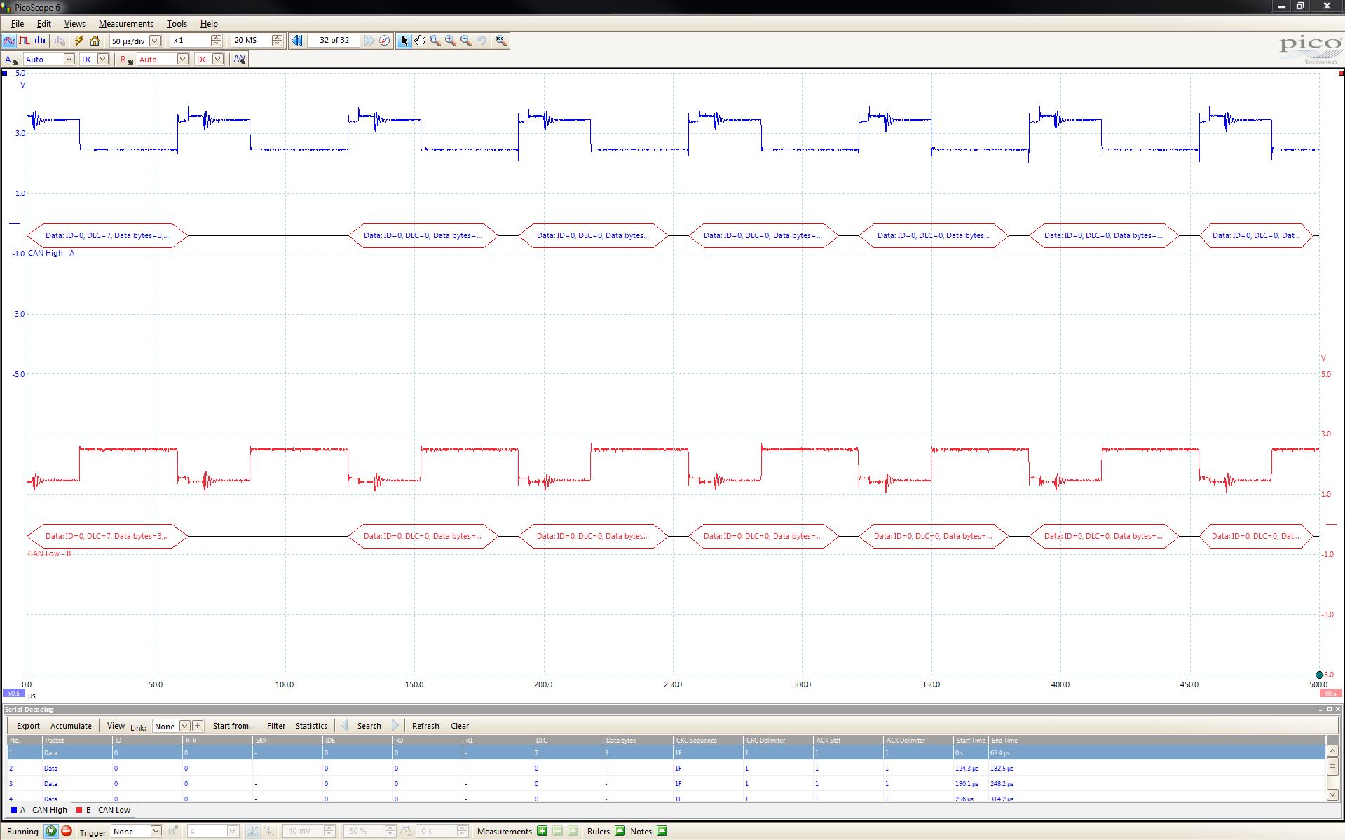
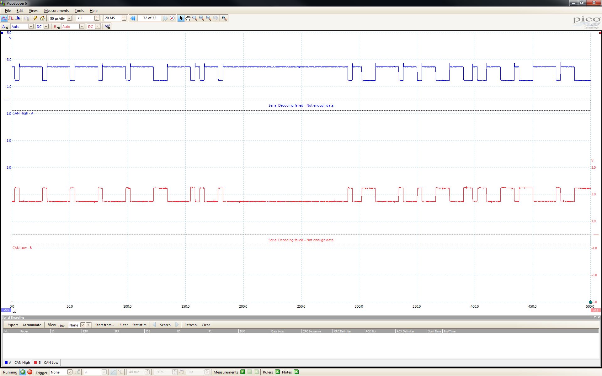
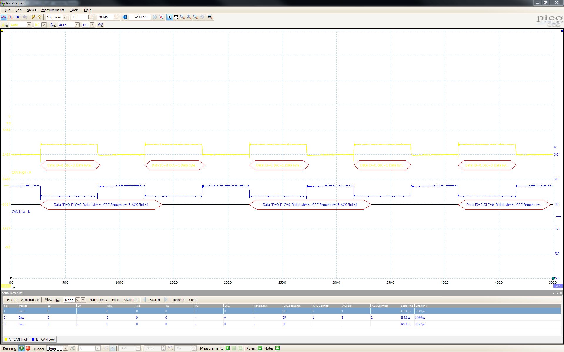
i am trying to set up a CAN bus and I am having trouble understanding what CAN tx and CAN rx represent in terms of hooking up a cable. I am used to CAN high and CAN low. Currently, I only have probes hooked up to the CAN tx (CAN Low - red) and CAN rx (CAN High - blue) and I am not sure if I am receiving data or not. Is this correct?

4331.CAN_Controller.zip

  • Hello Andrew,

    The CAN Bus is a shared bus topology. Normally the CAN TX and RX is connected to a CAN Transciever. So whatever the CAN controller transmits it is able to listen as well.

    The key is to find a transceiver if you want to build the CAN n/w. TI does have CAN transceiver. But to flow flush you can use the loopback mode where the CAN controller TX pin is internally connected to the RX, so that it can receive messages that it transmits.

    What you are seeing is because the CAN RX may not be connected to anything, so it is not getting any data back.

    Regards

    Amit

  • Amit,

    So, if I use the MCP2551 chip as the CAN transceiver then I will be able to send and receive messages on the CAN bus?

  • Hello Andrew

    Yes, that should do. I haven't used the MCP2551 chip though as I have TI SN65HVD1050.

    Regards

    Amit

  • I am using the MCP2551 chip as the transceiver with the TM4C1294 and I am unable to generate any CAN messages. I have attached a schematic of my hardware configuration and I am only viewing the CAN High and CAN Low pins on a scope. My code is attached below as well. What am I doing wrong?

    1072.CAN_Controller.zip

  • Hello Andrew

    Some HW study on this device is needed (my homework). BTW why is there a 60Ohm termination (I have used 120ohms as termination (and so does the CAN Bus Specification).

    Regards

    Amit

  • Hello Amit,

    I am using a 60 ohm termination because the system I plan to interface with specifies this requirement but I can try a 120 ohm resistor for now.

  • Hello Andrew,

    There are a few things to check (not very concerned on 60Ohms right now)

    1. Is the TX Pin toggling?

    2. Is the CANH and CANL changing as expected?

    3. The RX pin has a VOH min of 0.7VDD which would work out as 3.5V (min). The TM4C129 IO's are not 5V tolerant, which may cause IO degradation.

    4. Is what is being sent over the CAN Bus reflecting on the RX line?

    A scope plot would be useful...

    Regards

    Amit

  • Amit,

    1) The TX pin is not toggling. The TX pin is Low.

    2) The CANH and CANL pins are not changing at all. CANH and CANL are both at 2.25V with a VDD of 3.3V.

    3) I just changed VDD to 3.3V so will that help with the degradation?

    4) There is nothing being received on the RX line. The RX pin is High.

    I have attached a plot of CANH (blue) and CANL (red) and a plot of TX (blue) and RX (red) on the scope but there is nothing to really show since nothing seems to be on the CAN bus.

    CANH/CANL

    TX/RX

  • Hello Andrew

    A close inspection of the code shows a potential problem

        SysCtlPeripheralEnable(SYSCTL_PERIPH_GPIOB);

    instead of

        SysCtlPeripheralEnable(SYSCTL_PERIPH_GPIOA);

    which is required for the GPIO to be configured for CAN function on Port A.

    Regards

    Amit

  • Amit,

    I'm sorry about that code issue but I am still having the same problem of not getting any traffic on the CAN bus. However, the TX pin is now High.

  • Hello Andrew,

    The MCP2551 requires 4.5V-5.5V, so changing the VDD is not the correct option. You would need level translator on the RXD path.

    However, this should not have any bearing to the TX pin not toggling at all. As I have 2 other CAN issues to look into (other than your post), I should be able to get some more info from the TI Transceiver which may help you. I will add to the post hopefully in the next 2 days.

    Regards

    Amit

  • Amit,

    Ok, thank you for your help!

  • Hello Andrew

    I have attached the code for EK-TM4C129

    http://e2e.ti.com/cfs-file.ashx/__key/communityserver-discussions-components-files/908/5315.TM4C129_5F00_CAN0_5F00_TxSide.7z

    I have tested the same by connecting the TX and RX pin of CAN and checked it on a scope that the transmission happens (even though ACK will not be done).

    When the CAN pins are connected to a TI transceiver, the RX pin shows the same as what TX pin except that it is at 5V.

    The RX Pin from the transceiver must be high when the TX pin to the transceiver is high.

    Regards

    Amit

  • Amit,

    I am using your code now and I do see that TX and RX are both high but I don't seem to be seeing anything transmitting on the CANH and CANL lines. What are you seeing on your CANH and CANL lines because my scope is readying 2.5V for both lines.

  • Hello Andrew,

    In my case the CANH and CANL toggle as shown in the scope capture below.

    Regards

    Amit

  • Amit,

    Wow! I am not getting any of that. I'll continue to trouble shoot my setup but whats the part number for the transceiver that you are using? How do you have it wired?

  • Hello Andrew,

    I am using the TI Transceiver SN65HVD1050

    Pin-1: CANTX

    Pin-2: GND

    Pin-3: VCC (+5V)

    Pin-4: CANRX

    Pin-5: NC

    Pin-6: CANL

    Pin-7: CANH

    Pin-8: GND

    If you have another of the MCP parts, you may want to check a new device (just in case the existing one has gone bad)

    Regards

    Amit

  • Amit, 

    I did have an extra transceiver but I still had no luck with that one either. I may just order this transceiver so that we can be on the same playing field. Thanks for your help. I'll let you know if I make and progress.

  • Amit,

    I got to finally work. I unplugged the USB cord for the TM4C1294 while the code was running and after I plugged it back in, I began to see transmissions. Weird, I know. Thanks again though!

  • Hello Andrew,

    Personally, such weird behaviors are precursors to larger problems especially when developing code. Since this would not be the final code, it would be good to understand why, because it is not a good idea to unplug-plug USB every time.

    Can you send a picture of the board (to review the jumpers, etc)?

    Regards

    Amit

  • Amit,

    I will admit, I did a few things extra too. I replaced that 10k Ohm from Rs to ground with a short to ground. I also swapped out some wires to ensure I got a solid connection. I did all of this while the code was still running but I didn't see any differences until power cycled the board but I believe one of those 1st two changes probably fixed the problem. I'll keep an eye on it though.

  • Amit,

    I am not sure if you have CANalyzer to test this or if you are familiar with CANalzyer but I am trying to see if the CAN messages that I am sending from the TM4C1294 will be read into CANalyzer. I have a few different screen shots of things I have tried to get it to work but with no avail. I wanted to know if you understand any of the error messages below.

    This is a scope plot of what I am trying to send into CANalyzer. This is what the traffic looks like before connecting my CAN Case XL.

    This is a scope plot of the Transmission error that I get when connecting CANH of the transceiver to the CANH of the CAN Case XL and connecting CANL of the transceiver to the CANL of the CAN Case XL.

    This is a scope plot of the ACK Slot error that I get when connecting CANH of the transceiver to the CANL of the CAN Case XL and connecting CANL of the transceiver to the CANH of the CAN Case XL.

  • Hello Andrew,

    No, I haven't use a CANanlyzer. May be the forum folks may be able to help.

    Regards

    Amit

  • Amit,

    Ok, thanks! 

    You mentioned that you were receiving/transmitting CAN messages without an ACK. What exactly did you mean by that? Is there more that I need to add to my code in order to send an ACK for received messages or something?

  • Hello Andrew,

    In my setup I have two other CAN Nodes that are receiving specific Messages from the Transmitter. So I always get an ACK.

    To help debug the issue you were facing, I removed the slaves, so that the transmitter would send the data but not receive an ACK, to make sure that in a simplistic topology the code and the transceiver are working.

    In the following post I have added the code for a single receiver (also a TM4C129 but on CAN-1).

    http://e2e.ti.com/support/microcontrollers/tiva_arm/f/908/t/363647.aspx

    Regards

    Amit

  • So if I want to transmit and receive CAN messages with my one TM4C1294 board then I also need to add this RX code that you just provided?

  • Hello Andrew,

    Yes. You can integrate the RX code on another EK board.

    Regards

    Amit

  • Hello Amit,

    I have run into another problem all of a sudden.  I am now receiving the error "CAN_STATUS_LEC_BIT1". I see that it says that "The buss remained a bit level of 1 for longer than is allowed" but what does that mean and how do I fix it?

  • Hello Andrew,

    It would mean that when the device was transmitting a 1, the other node was sending 0 which caused the dominant 0 to be reflected. This is typical of arbitration loss and would require a re-transmit of the message,

    Regards

    Amit

  • Amit,

    What do you suggest I do to try and fix it because it seemed to randomly start generating this error after it had been working for a week.

  • Hello Andrew,

    One thing to check is after the first power on reset, clear the SYSCTL.RESC register and when it gives the error to check if there is no other reset happening.

    Second thing to try is to use the internal PIOSC for locking the PLL, to check if the Main Crystal is not creating a problem.

    Regards

    Amit

  • Amit,

    I was trying to change the clock settings for the board and now I am getting an error with connecting to the target. I changed:

    ui32SysClock = SysCtlClockFreqSet( ( SYSCTL_XTAL_16MHZ | SYSCTL_OSC_INT | SYSCTL_USE_PLL | SYS_CFG_VCO_480 ), 120000000 ) 

    to

    ui32SysClock = SysCtlClockFreqSet( ( SYSCTL_SYSDIV_1 | SYSCTL_OSC_INT | SYSCTL_USE_PLL | SYS_CFG_VCO_480 ), 120000000 )

    I understand that probably wasn't the correct thing to do but I was only trying things. But after flashing that code change to the board, I can no longer connect to the target. Any thoughts?

  • Hello Andrew

    You will have to use the LMFlashProgrammer to Unlock the device and then re-program with the correct code.

    Regards

    Amit

  • Amit,

    I tried looking up that SYSTCTL.RESC in the documentation and didn't see that syntax. How exactly do I reset that register?

    Furthermore, how do I lock the PLL with the internal PIOSC?

  • Hello Andrew

    The API to get the cause of reset is following. Similarly, there is another API to clear it.

    SysCtlResetCauseGet()

    To use the internal PIOSC for locking the PLL you may use

    SysCtlClockFreqSet((SYSCTL_XTAL_16MHZ |
                                                 SYSCTL_OSC_INT |
                                                 SYSCTL_USE_PLL |
                                                 SYSCTL_CFG_VCO_480), 120000000);

    Regards

    Amit

  • Amit,

    Apparently, I am already using the internal PIOSC for locking the PLL because that is exactly how my clock is currently set up. However,  I will add SysCtlResetCauseGet() to the code and see whats happening. I will give you an update shortly.

  • When I read the return value from the SysCtlResetCauseGet() function, I get a return value of 3. I looked that value up in sysctl.h and there is no return value listed with the value of 3.

  • Hello Andrew,

    The value returned by the function for SYSCTL.RESC register has a bit wise encoding. the value 0x3 would mean a POR and EXT reset. It would be good to clear the register the first time around when you load the code. After that if a BOR/POR occurs on reboot of the application code get the code hang into a while(1) loop.

    Also as you mentioned the code is already using PIOSC, it would mean that MOSC is not an issue here.

    Next do make sure that the wiring between TM4C and Transciever and the cabling on the CAN Bus is well-soldered.

    Lastly, as mentioned previously, on receiving a LEC1, do try to retransmit the message. Does the retransmit succed?

    Regards

    Amit

  • Amit,

    The code gets hung up in the followig loop.

    //
    // Wait for the indication from the interrupt handler that message
    // object 3 is done, because we are re-using it for another message.
    //
    while(!g_bMsgObj3Sent)
    {
    }

    I have already tried putting SysCtlResetCauseGet() inside this loop and it still returned a value of 0x03. I will try just sending my message only but I don't understand why it's not working now when it did before.

  • Hello Andrew,

    Looks like all probable cause for an issue are not there.

    It is rather difficult to debug what is going wrong after some time of the CAN controller working.

    Forum Members (any suggestion/ideas are most appreciated) may be able to help.

    Regards

    Amit

  • Hi, sorry for opening an old topic. I am currently using EK-TM4C1294XL and working on CAN bus. I tried to implement the 5315.TM4C129_CAN0_TxSide file that Amit provided. However, no luck. Here are the steps that I took:
    1. I downloaded the zip file and unzipped it.
    2. I moved it to the right directory to my workspace.
    3. I made necessary adjustment of the include options, without modyfing the code.
    4. I adjusted JP4 and JP5 on my board so that they are || instead of =.
    5. I built and ran the project.

    However, when I measure the CAN Tx (PA1) on my board, I always get a 1. That means it is not toggling, right?

    Did I miss anything?

    PS: I also tried to modify the simple can examples from Texas Instruments, but still no luck
  • Hello Hermawan

    Is the CAN Rx pin connected to a transceiver?
  • Hi Amit,

    Yeah. I did not put a transceiver. After trying with transceivers, I could send the CAN messages. Thanks!

    I did not know that the transceiver was more than 'just a level shifter' and its presence is important to the microcontroller.

    Many thanks,

    Hermawan Mulyono
  • Hello Hermawan,

    Let me explain what was happening. When the Transceiver was not connected the CAN RX pin was low. a low on the CAN bus means a recessive signal, i.e. the CAN bus is being driven low by some other device. When a low is detected the CAN transmission cannot be started.
  • Hi Amit,

    Thank you very much for your explanation. It helped me a lot!!

    Regards,

    Hermawan Mulyono