Hi,
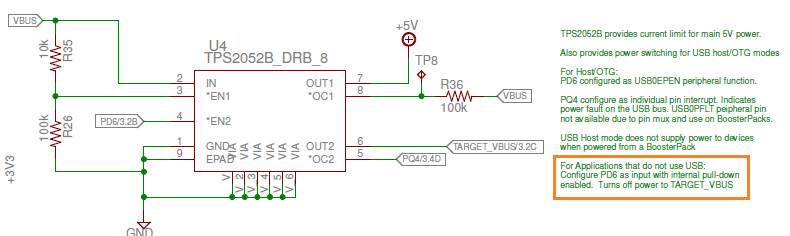
can I harm the MCU by configuring PB1 as output? VBUS's 5V is directly connected to this pin. I think accidentally configured to output. Now the simple blinky example is not working.
Thanks,
Peter
Hi,
can I harm the MCU by configuring PB1 as output? VBUS's 5V is directly connected to this pin. I think accidentally configured to output. Now the simple blinky example is not working.
Thanks,
Peter