This thread has been locked.

If you have a related question, please click the "Ask a related question" button in the top right corner. The newly created question will be automatically linked to this question.

Problems with new design (TM4C1230E6PM), newbie questions

Other Parts Discussed in Thread: TM4C1230E6PM, EK-TM4C123GXL

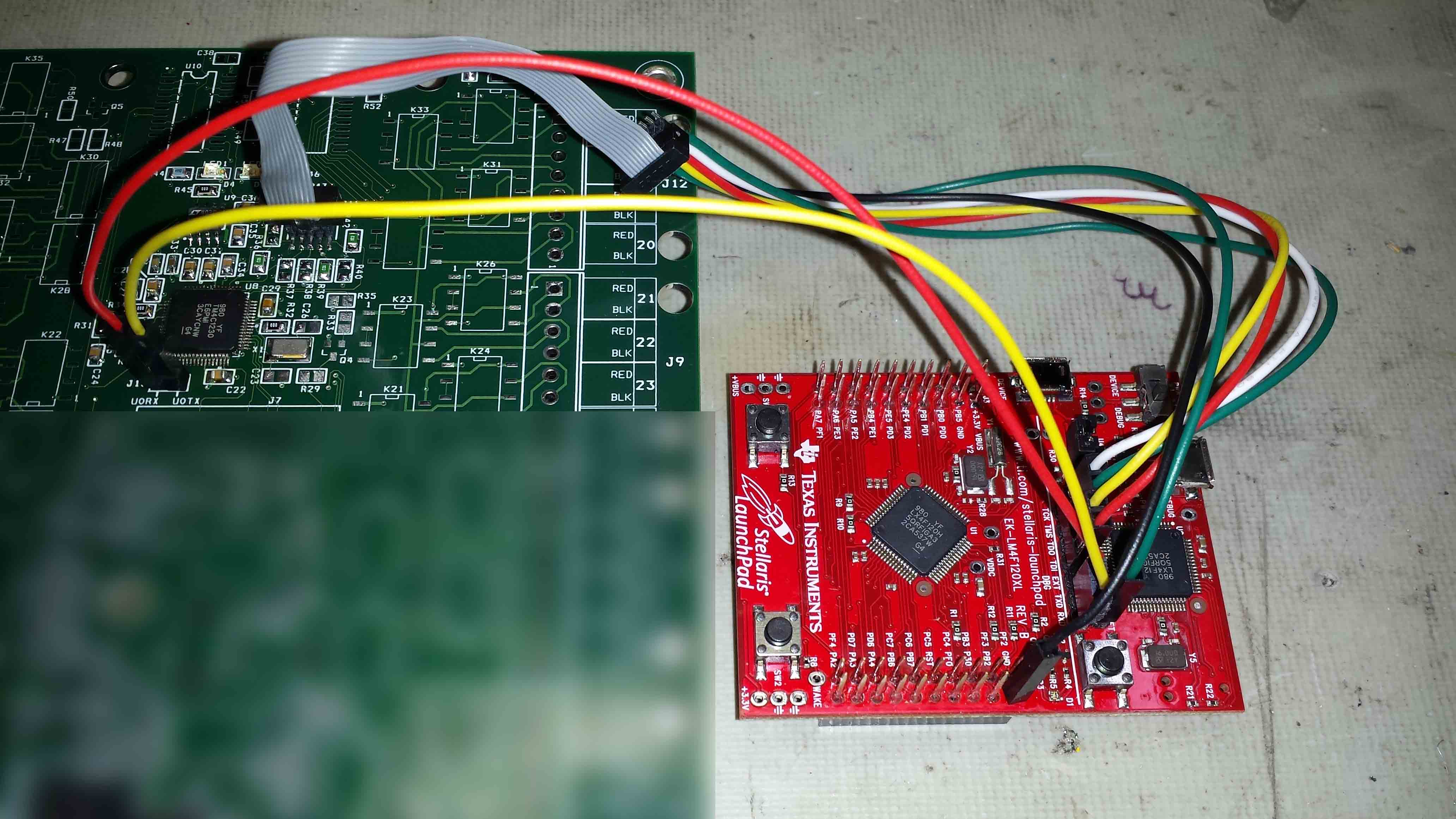
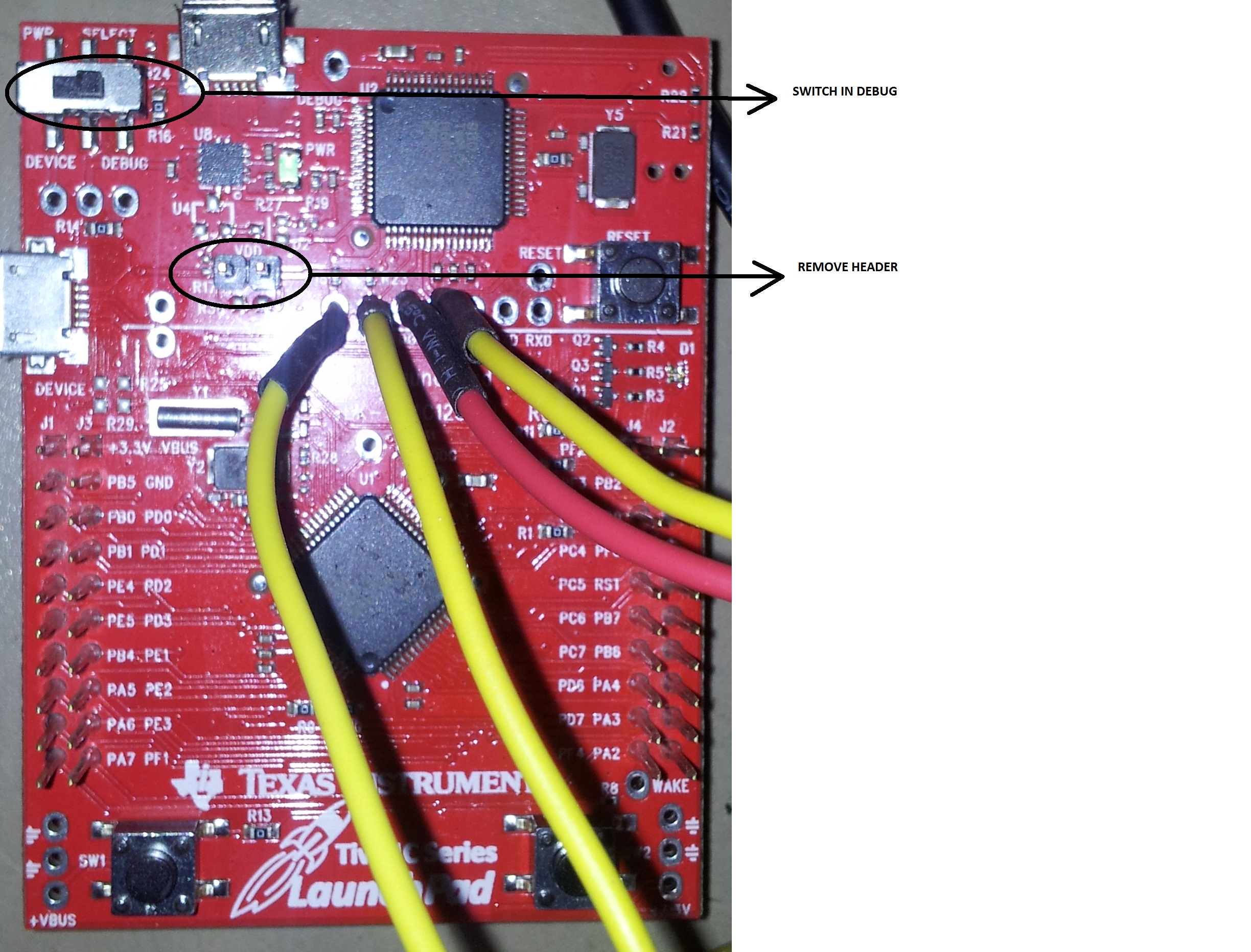
Hello all, I am a newbie at microcontrollers and have been developing a product using the LM4F120 Launchpad and IAR Embedded Workbench.  The initial code development has been going very well.  In the new design we chose the TM4C1230E6PM.  I am now in the process of starting up the first PCB, and am having issues with initial board startup.  I am using the Launchpad configured for Debug Out per this link: http://processors.wiki.ti.com/index.php/Stellaris_LM4F120_LaunchPad_Debug_How_To

I have not been able to locate a schematic for a reference design using the TM4C1230E6PM.

When trying to debug with the Launchpad in Debug Out into the target, IAR throws a failure to initialize JTAG error.  I did set the Device in Options in IAR to TM4C1230E6PM.  I have double checked the connections between the Launchpad and target.  If I set the Launchpad back to its internal target, it will initialize and work correctly. 


I also probed the OSC pins 40 and 41 of the TM4C1230E6PM with a scope, and see only around 1VDC.  The internal regulator voltages (pins 25 and 56) plus VCC appear to be correct.


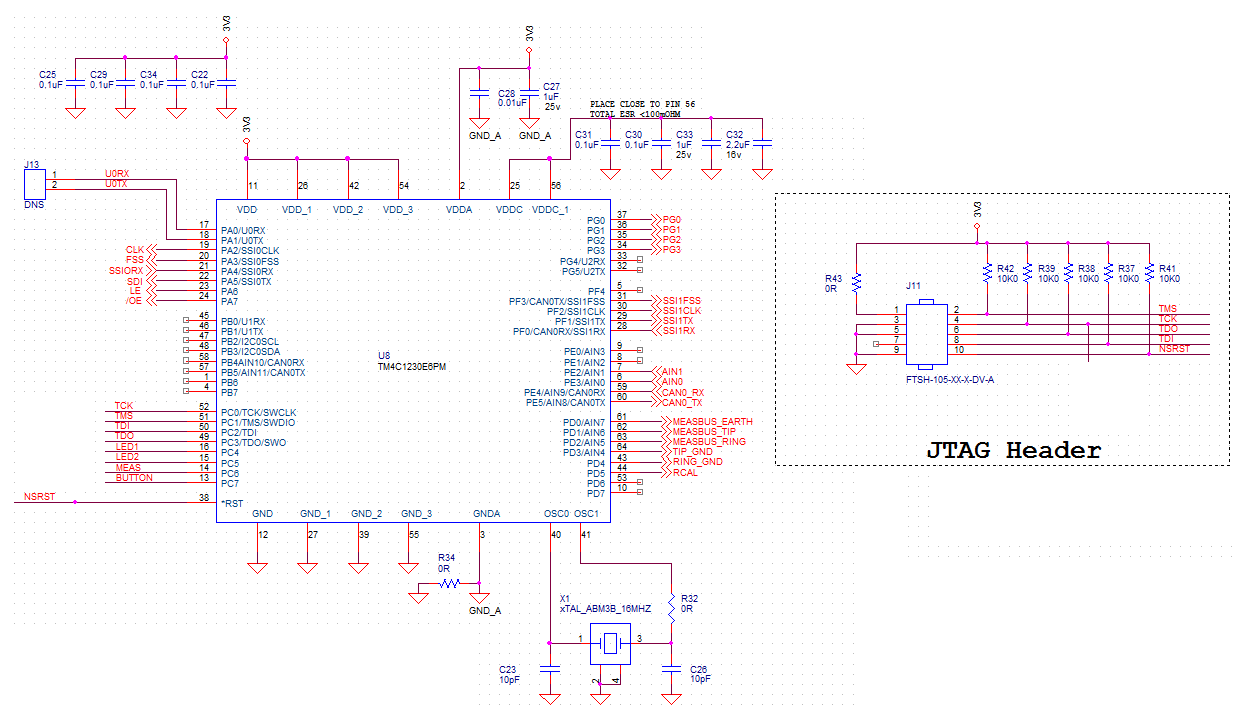
Pleas find an image of the target schematic attached.  My questions are:

1)  With a new TM4C1230E6PM set up like the target schematic, should the OSC pins show oscillation, or is there setup or pin transitions required?  Or does the uC use the internal oscillator and will not show any external indication of clock operation until the external clock is configured?  The answer will help me to determine if maybe my uC is shot and needs to be replaced, or if there is a PCB error.


2) Is there perhaps a pin on the TM4C1230E6PM, such as /WAKE on the LM4F120, that needs to be pulled high or low for the uC to wake up?

3) Should the LM4F120 Launchpad be able to work as a debug JTAG for a target with a TM4C1230E6PM?

Thank you very much for all responses and help.

  • Hello Mark,

    Yes, the LM4F120 debug out should work as a debugger for TM4C parts. Can you send a snapshot of how the LM4F120 has been wired for use as external debug out? And also how it is being wired to your board?

    Secondly, the TM4C devices come with empty flash which causes the internal ROM boot loaders to lock the PLL using the OSC. Hence you would see oscillations even if the flash code is not there. Also since the boot loaders are active, there is no need to pull up any pin.

    Regards

    Amit

  • Hello Amit, thank you very much for your help.  To use the LM4F120 as a debugger, I followed the TI blog post I linked in the original post, and carefully triple checked the connections.   Image is attached below.

    I originally suspected that there may be an issue with my PCB or soldering of the uC on the target, since I do not see any oscillations from the uC.  Hearing that the clock should always be present confirms this.   I would suspect that no clock would also keep the debugger from initializing.

    I will try removing/replacing the TM4C to ensure there are no shorts that are keeping it from waking up.


    Thanks again for the help!

  • Hello Mark,

    If I get the image correct, on the LaunchPad you would need to remove the jumper on R30 resistor.

    Regards

    Amir

  • The block is still on the connector, but is only making contact with one of the pins from the Stellaris.  The two pins are not connected with the block.


    Thanks,

    Mark

  • Hello Mark,

    In the past I have used EK-TM4C123GXL LaunchPad (identical to the Stellaris LaunchPad).

    1. Keep the Switch in Debug Mode

    2. Remove the VDD Header

    3. Connect the JTAG Wires as shown in the center of the board.

    Can you do the following

    1. Scope the JTAG Lines. Does TDO toggle as expected

    2. Remove the OSC and GND OSC0 pin to make sure that it is not an external oscillator issue

    3. Connect the RST from the Debug Interface to the Main Board

    4. If none of the above work, try using another external debugger to isolate the issue to the LaunchPad or the Main Board

    I know it is a lot to ask, but that is what i have done when doing custom board debug.

    Regards

    Amit

  • Hello Amit, thanks again for your thorough help and suggestions.  I am currently working through the list of items you posted, first of all looking for another accessible debugger.

    One question that is vexing me however:  Say if you took a new unused TM4C1230 and did the following:

    1) Install it on a breadboard

    2) Add the proper capacitance to the VDD, VDDA and VDDC pins

    3) Pull the reset pin high

    4) Apply 3.3V to VDD/VDDA

    5) Verify proper VDD/VDDA and VDDC within limits

    In the above minimal setup, with no debugger connected, should I be able to see the TM4C1230's internal 16mHz clock oscillate by probing pin OSC1?  Or will any clocking prior to programming have to be provided by the debugger?

    I will report back ASAP on the other tests.  Thanks,

    Mark

  • Hello Mark,

    No, the OSC1 pin will not output the internal 16MHz clock. In addition to the 5-points mentioned above ensure that OSC0 is also GND-ed as the Oscillator detection circuit may detect noise as valid clock signals causing issues of JTAG connectivity.

    Regards

    Amit

  • Hello Amit, thanks for the info on the OSC pins.  I continued troubleshooting with the assumption that the uC was OK, also grounded OSC0 as you suggested.  I basically found the following things:


    I had TDO and TDI switched at the Launchpad.  Switched those to what they were supposed to be.

    I also checked TDO for toggling at the Launchpad, it did not toggle during an attempt at starting a debug session.  However TDI did toggle at the Launchpad, as well as TCK.  (this is when connected to the external target PCB)

    I do not have another debugger that I can get to easily work with IAR, but will start looking at getting one this week.

    I probed RST, and it seemed locked at 1.9V, which seemed strange.  It looked like it was trying to toggle during a debug session, but would only change a few hundred mV.  When the external target was removed and the internal Launchpad target enabled, NSRST went up to 3.3V and worked correctly.  I do not know what is going on here; my target has a single 10k pullup on NSRST.  Perhaps I need to add a buffer to this line to unload it from the Launchpad?  In any case it may be possible that the RST line on the Launchpad was causing the external target to remain in reset.

    BTW, pressing the reset button on the Launchpad did pull the reset line on the external target fully to 0v.

    Seeing that your last picture did not have NSRST connected, I disconnected NSRST from the external target and started a debug session, this time the session progressed much farther but still reported a "Stack pointer set to incorrect alignment" error.  This seems to me to suggest that the debugger is now working to a point, and I might have a code error (perhaps somewhere in the code the target is still set to a LM4F120 and not a TM4C1230E6PM).  I did set the uC option in IAR to the TM4C uC.


    So overall we are getting closer, and you answered my original question, and have been of much help in other areas.  Please send any info you may have on the RST pin issue, but other than that, we can consider the issue closed.  Thanks again for all of your help, I really appreciate it.

    Mark

  • Hello Mark,

    That is good news. My suspicion is that there is a weak pull down on the Reset Pin which is why the voltage remains at ~1.9V. It is not a good voltage to have on RST_N pin as the uC may have trouble making sense of RST_N pin

    You may want to check the RST_N being pulled up by different strengths to see what is the effective "pull down" which may help isolate it on the boards

    Regards

    Amit