Other Parts Discussed in Thread: TM4C123GH6PM
Hello, my name is Juan Carlos
I'm working with a Tiva Launchpad (TM4C123GH6PM), and I try communicate this board with a L3GD20 sensor.
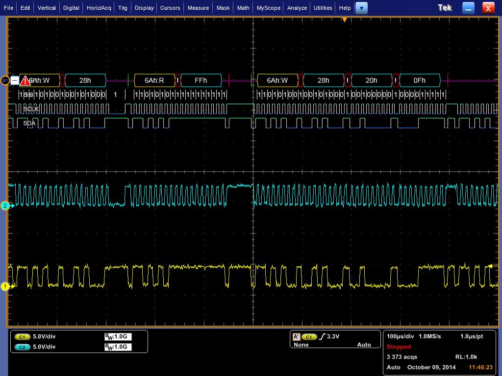
My problem is the transfer the slave address, because I can see the signal of SDA and SCL in the oscilloscope, and I see that this is wrong. Send the image of the signal transfer and write my code.
The slave addres in the signal is 0x54h while the slave addres in code is 0xD4h. I think that the bit MSB in the slave address is lost, i don't know why.
Thanks for your answers.
void L3gd20_Init(void)
{
I2CMasterSlaveAddrSet(I2C0_BASE,0xD4,false);
I2CMasterControl(I2C0_BASE, I2C_MASTER_CMD_BURST_SEND_START);
while(I2CMasterBusy(I2C0_BASE));
SysCtlDelay(10);
I2CMasterDataPut(I2C0_BASE, 0xD4);
I2CMasterControl(I2C0_BASE, I2C_MASTER_CMD_BURST_SEND_CONT);
while(I2CMasterBusy(I2C0_BASE));
SysCtlDelay(10);
I2CMasterDataPut(I2C0_BASE, 0x20);
I2CMasterControl(I2C0_BASE, I2C_MASTER_CMD_BURST_SEND_CONT);
while(I2CMasterBusy(I2C0_BASE));
SysCtlDelay(10);
I2CMasterDataPut(I2C0_BASE, 0x0F);
I2CMasterControl(I2C0_BASE, I2C_MASTER_CMD_BURST_SEND_FINISH);
while(I2CMasterBusy(I2C0_BASE));
}
uint8_t ByteReadL3GD20(uint32_t address)
{
uint8_t addr,dato;
addr=address;
I2CMasterSlaveAddrSet(I2C0_BASE, 0xD4 ,false);
I2CMasterDataPut(I2C0_BASE, addr);
I2CMasterControl(I2C0_BASE, I2C_MASTER_CMD_BURST_SEND_START);
while(I2CMasterBusy(I2C0_BASE));
SysCtlDelay(100);
I2CMasterSlaveAddrSet(I2C0_BASE, 0xD5, true);
I2CMasterControl(I2C0_BASE, I2C_MASTER_CMD_SINGLE_RECEIVE);
while(I2CMasterBusy(I2C0_BASE));
I2CMasterControl(I2C0_BASE, I2C_MASTER_CMD_BURST_RECEIVE_FINISH);
while(I2CMasterBusy(I2C0_BASE));
dato=I2CMasterDataGet(I2C0_BASE);
return I2CMasterDataGet(I2C0_BASE);
}
int main(void)
{
uint8_t gX[2]={0,0};
uint8_t gY[2]={0,0};
uint8_t gZ[2]={0,0};
SysCtlClockSet(SYSCTL_SYSDIV_20| SYSCTL_USE_PLL | SYSCTL_OSC_MAIN | SYSCTL_XTAL_16MHZ);
//HABILITACIÓN DE PERIFERICOS================================
SysCtlPeripheralEnable(SYSCTL_PERIPH_UART0);
SysCtlPeripheralEnable(SYSCTL_PERIPH_UART3);
SysCtlPeripheralEnable(SYSCTL_PERIPH_I2C0);
SysCtlPeripheralReset(SYSCTL_PERIPH_I2C0);
SysCtlPeripheralEnable(SYSCTL_PERIPH_ADC0);
SysCtlPeripheralEnable(SYSCTL_PERIPH_GPIOA);
SysCtlPeripheralEnable(SYSCTL_PERIPH_GPIOB);
SysCtlPeripheralEnable(SYSCTL_PERIPH_GPIOC);
//CONFIGURACION DE UARTS=====================================
GPIOPinConfigure(GPIO_PA0_U0RX); //Debug
GPIOPinConfigure(GPIO_PA1_U0TX);
GPIOPinTypeUART(GPIO_PORTA_BASE, GPIO_PIN_0 | GPIO_PIN_1);
GPIOPinConfigure(GPIO_PC6_U3RX); //CPU
GPIOPinConfigure(GPIO_PC7_U3TX);
GPIOPinTypeUART(GPIO_PORTC_BASE, GPIO_PIN_6 | GPIO_PIN_7);
UARTConfigSetExpClk(UART0_BASE, SysCtlClockGet(), 115200,
(UART_CONFIG_WLEN_8 | UART_CONFIG_STOP_ONE | UART_CONFIG_PAR_NONE));
UARTConfigSetExpClk(UART3_BASE, SysCtlClockGet(), 115200,
(UART_CONFIG_WLEN_8 | UART_CONFIG_STOP_ONE | UART_CONFIG_PAR_NONE));
//CONFIGURACION DE I2C=====================================
GPIOPinConfigure(GPIO_PB2_I2C0SCL);
GPIOPinConfigure(GPIO_PB3_I2C0SDA);
GPIOPinTypeI2C(GPIO_PORTB_BASE, GPIO_PIN_3); //SDA
GPIOPinTypeI2CSCL(GPIO_PORTB_BASE, GPIO_PIN_2); //SCL
I2CMasterInitExpClk(I2C0_BASE, SysCtlClockGet(), false);
HWREG(I2C0_BASE + I2C_O_FIFOCTL) = 80008000;
I2CMasterEnable(I2C0_BASE);
//CONFIGURACION DE TERMINALES DE SALIDA=======================
//CONFIGURACION DE TERMINALES DE ENTRADA=======================
// CONFIGURACION DE CANALES DE CONVRESION ANALOGICA DIGITAL======
// CONFIGURACION SPI==============================================
//========================================================
//CONFIGURACIONES DE INTERRUPCIONES
//INTERRUPCION DE GPIO's
//INTERRUPCION DE COMUNICACIONES
//========================================================
L3gd20_Init();
UARTSend(UART0_BASE,(const unsigned char *)&"Programa I2C",18);
UARTSend(UART0_BASE,(const unsigned char *)&"\n\r",3);
UARTSend(UART3_BASE,(const unsigned char *)&"Programa I2C",18);
UARTSend(UART3_BASE,(const unsigned char *)&"\n\r",3);
while(1)
{
gX[0]=ByteReadL3GD20(0x28);
SysCtlDelay(100);
}
}
Signal of the : " L3gd20_Init();"
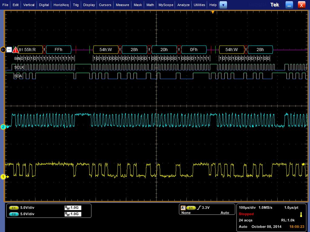
Signal of the " gX[0]=ByteReadL3GD20(0x28); "