Other Parts Discussed in Thread: TM4C123GH6PM, LMFLASHPROGRAMMER, UNIFLASH
Using CCSv6, Win8.1, TivaC 123 Launchpad, Blackhawk XDS100v2,
I am trying to Debug-In* to the U1 TM4C123G which is on the Launchpad, with my XDS100v2 so that I can program the mcu without the ICDI. However, my attempts at doing so through CCS are being met with the following error:
Error connecting to the target:
(Error -1170 @ 0x0)
Unable to access the DAP. Reset the device, and retry the operation. If error persists, confirm configuration, power-cycle the board, and/or try more reliable JTAG settings (e.g. lower TCLK).
.* http://processors.wiki.ti.com/index.php/Stellaris_LM4F120_LaunchPad_Debug_How_To
My ccxml file is basic:
<?xml version="1.0" encoding="UTF-8" standalone="no"?>
<configurations XML_version="1.2" id="configurations_0">
<configuration XML_version="1.2" id="Texas Instruments XDS100v2 USB Emulator_0">
<instance XML_version="1.2" desc="Texas Instruments XDS100v2 USB Emulator_0" href="connections/TIXDS100v2_Connection.xml" id="Texas Instruments XDS100v2 USB Emulator_0" xml="TIXDS100v2_Connection.xml" xmlpath="connections"/>
<connection XML_version="1.2" id="Texas Instruments XDS100v2 USB Emulator_0">
<instance XML_version="1.2" href="drivers/tixds100v2cs_dap.xml" id="drivers" xml="tixds100v2cs_dap.xml" xmlpath="drivers"/>
<instance XML_version="1.2" href="drivers/tixds100v2cortexM.xml" id="drivers" xml="tixds100v2cortexM.xml" xmlpath="drivers"/>
<platform XML_version="1.2" id="platform_0">
<instance XML_version="1.2" desc="Tiva TM4C123GH6PM_0" href="devices/tm4c123gh6pm.xml" id="Tiva TM4C123GH6PM_0" xml="tm4c123gh6pm.xml" xmlpath="devices"/>
</platform>
</connection>
</configuration>
</configurations>
If I use the "Test Connection" feature, then I get the following output:
[Start: Texas Instruments XDS100v2 USB Emulator_0]
Execute the command:
%ccs_base%/common/uscif/dbgjtag -f %boarddatafile% -rv -o -F inform,logfile=yes -S pathlength -S integrity
[Result]
-----[Print the board config pathname(s)]------------------------------------
C:\Users\...\AppData\Local\TEXASI~1\
CCS\ti\0\0\BrdDat\testBoard.dat
-----[Print the reset-command software log-file]-----------------------------
This utility has selected a 100- or 510-class product.
This utility will load the adapter 'jioserdesusb.dll'.
The library build date was 'May 21 2014'.
The library build time was '17:19:59'.
The library package version is '5.1.507.0'.
The library component version is '35.34.40.0'.
The controller does not use a programmable FPGA.
The controller has a version number of '4' (0x00000004).
The controller has an insertion length of '0' (0x00000000).
This utility will attempt to reset the controller.
This utility has successfully reset the controller.
-----[Print the reset-command hardware log-file]-----------------------------
The scan-path will be reset by toggling the JTAG TRST signal.
The controller is the FTDI FT2232 with USB interface.
The link from controller to target is direct (without cable).
The software is configured for FTDI FT2232 features.
The controller cannot monitor the value on the EMU[0] pin.
The controller cannot monitor the value on the EMU[1] pin.
The controller cannot control the timing on output pins.
The controller cannot control the timing on input pins.
The scan-path link-delay has been set to exactly '0' (0x0000).
-----[The log-file for the JTAG TCLK output generated from the PLL]----------
There is no hardware for programming the JTAG TCLK frequency.
-----[Measure the source and frequency of the final JTAG TCLKR input]--------
There is no hardware for measuring the JTAG TCLK frequency.
-----[Perform the standard path-length test on the JTAG IR and DR]-----------
This path-length test uses blocks of 512 32-bit words.
The test for the JTAG IR instruction path-length failed.
The JTAG IR instruction scan-path is stuck-at-zero.
The test for the JTAG DR bypass path-length failed.
The JTAG DR bypass scan-path is stuck-at-zero.
-----[Perform the Integrity scan-test on the JTAG IR]------------------------
This test will use blocks of 512 32-bit words.
This test will be applied just once.
Do a test using 0xFFFFFFFF.
Test 1 Word 0: scanned out 0xFFFFFFFF and scanned in 0x00000000.
Test 1 Word 1: scanned out 0xFFFFFFFF and scanned in 0x00000000.
Test 1 Word 2: scanned out 0xFFFFFFFF and scanned in 0x00000000.
Test 1 Word 3: scanned out 0xFFFFFFFF and scanned in 0x00000000.
Test 1 Word 4: scanned out 0xFFFFFFFF and scanned in 0x00000000.
Test 1 Word 5: scanned out 0xFFFFFFFF and scanned in 0x00000000.
Test 1 Word 6: scanned out 0xFFFFFFFF and scanned in 0x00000000.
Test 1 Word 7: scanned out 0xFFFFFFFF and scanned in 0x00000000.
The details of the first 8 errors have been provided.
The utility will now report only the count of failed tests.
Scan tests: 1, skipped: 0, failed: 1
Do a test using 0x00000000.
Scan tests: 2, skipped: 0, failed: 1
Do a test using 0xFE03E0E2.
Scan tests: 3, skipped: 0, failed: 2
Do a test using 0x01FC1F1D.
Scan tests: 4, skipped: 0, failed: 3
Do a test using 0x5533CCAA.
Scan tests: 5, skipped: 0, failed: 4
Do a test using 0xAACC3355.
Scan tests: 6, skipped: 0, failed: 5
Some of the values were corrupted - 83.3 percent.
The JTAG IR Integrity scan-test has failed.
-----[Perform the Integrity scan-test on the JTAG DR]------------------------
This test will use blocks of 512 32-bit words.
This test will be applied just once.
Do a test using 0xFFFFFFFF.
Test 1 Word 0: scanned out 0xFFFFFFFF and scanned in 0x00000000.
Test 1 Word 1: scanned out 0xFFFFFFFF and scanned in 0x00000000.
Test 1 Word 2: scanned out 0xFFFFFFFF and scanned in 0x00000000.
Test 1 Word 3: scanned out 0xFFFFFFFF and scanned in 0x00000000.
Test 1 Word 4: scanned out 0xFFFFFFFF and scanned in 0x00000000.
Test 1 Word 5: scanned out 0xFFFFFFFF and scanned in 0x00000000.
Test 1 Word 6: scanned out 0xFFFFFFFF and scanned in 0x00000000.
Test 1 Word 7: scanned out 0xFFFFFFFF and scanned in 0x00000000.
The details of the first 8 errors have been provided.
The utility will now report only the count of failed tests.
Scan tests: 1, skipped: 0, failed: 1
Do a test using 0x00000000.
Scan tests: 2, skipped: 0, failed: 1
Do a test using 0xFE03E0E2.
Scan tests: 3, skipped: 0, failed: 2
Do a test using 0x01FC1F1D.
Scan tests: 4, skipped: 0, failed: 3
Do a test using 0x5533CCAA.
Scan tests: 5, skipped: 0, failed: 4
Do a test using 0xAACC3355.
Scan tests: 6, skipped: 0, failed: 5
Some of the values were corrupted - 83.3 percent.
The JTAG DR Integrity scan-test has failed.
[End: Texas Instruments XDS100v2 USB Emulator_0]
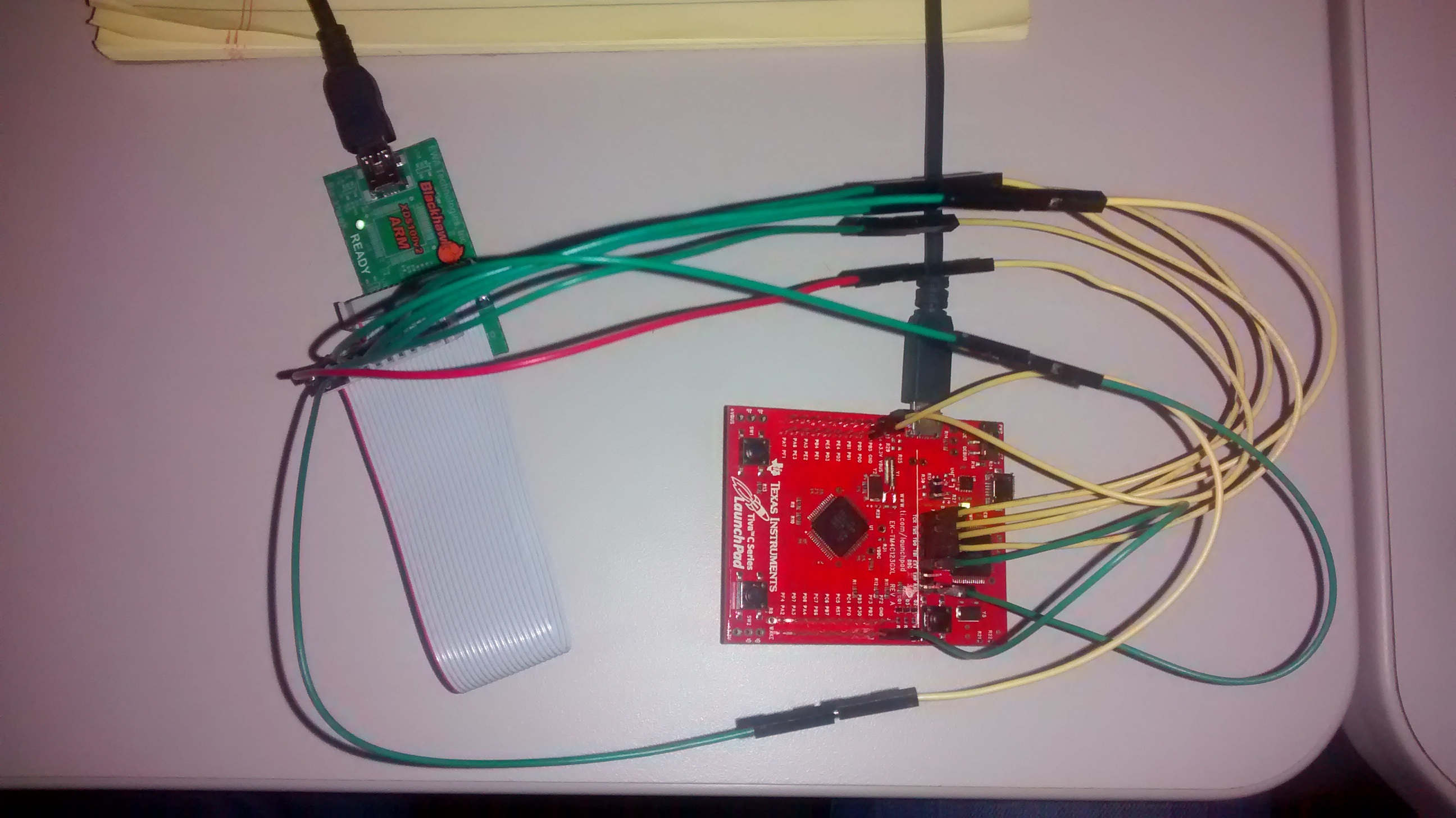
My TCK, TMS, TDO, TDI, Reset, GND pins are connected. Ext DBG is connected to GND. The VTref of the XDS is connected to the Launchpad +3.3V header pin. The Launchpad power select switch is set to "Device" and a USB cable is plugged into the device USB port. The one jumper which is usually on the board to connect power between the two mounted mcu's is removed.
Power cycling the assembly does not change the error messages.
The following posts appear to be similar/relevant but haven't resolved my issue:
http://e2e.ti.com/support/microcontrollers/tiva_arm/f/908/p/314189/1094336.aspx#1094336
http://e2e.ti.com/support/development_tools/code_composer_studio/f/81/t/348352.aspx?pi296443=2
http://e2e.ti.com/support/microcontrollers/tiva_arm/f/908/t/356869.aspx?pi307171=3
Does anyone have pointers w.r.t. achieving my objective?