This thread has been locked.

If you have a related question, please click the "Ask a related question" button in the top right corner. The newly created question will be automatically linked to this question.

TM4C fault ISR

Hiii all

please suggest mistakes in program lines given below. my code is going in fault ISR. but after removing these lines, its working fine.

float k,a;
unsigned long ulPeriod,p;
k=0.8;
ulPeriod = SysCtlClockGet() / 50000;
a=k*ulPeriod;
p=(long)a;

regards

Prashant

  • Hi,

    Please specify exactly what is your micro - TM4C has two families, with some incompatibilities - (with TM4C129 the function call SysCtlClockGet() is not allowed, for example).

    It is wise to debug and set some breakpoints and identify exactly the line which lead to FaultISR.

    Petrei

  • hi petrei

    i am using TM4C123G . and this multiplication is creating problem.

    regards

    prashant

  • If you use the softfp or hard ABI, you must enable the FPU, otherwise you end up in a fault handler.

    (It is NOT a fault interrupt, but a handler. Interrupts are asynchronous by definition.)

  • Hi,

    I agree with poster f.m.

    Please note also for such operations you do not need floating point (think about there are some micros, including old Stellaris, without FP unit). In this case, you may use a simple technique to get a fraction of a quantity, in your case, this way:

    a = (ulPeriod*8)/10; // or *800)/1000)

    Petrei

  • Hello Prashant,

    Please also do publish the result of the FAULTSTAT and FAULTADDR locations as mentioned in the post.

    http://e2e.ti.com/support/microcontrollers/tiva_arm/f/908/t/374640.aspx

    Regards

    Amit

  • #include <stdint.h>
    #include <stdbool.h>
    #include "inc/hw_gpio.h"
    #include "inc/hw_types.h"
    #include "inc/hw_memmap.h"
    #include "driverlib/sysctl.h"
    #include "driverlib/pin_map.h"
    #include "driverlib/gpio.h"
    #include "driverlib/pwm.h"
    #include "driverlib/adc.h"
    #include "driverlib/sysctl.h"
    #include<inc/tm4c123gh6pm.h>
    #include<driverlib/interrupt.h>
    #include<driverlib/timer.h>
    #include<driverlib/fpu.h>
    void PortBIntHandler(void);
    void PortBInit(void);
    void pwminit(void);
    volatile unsigned long ui32Loop,Count;
    volatile unsigned long Old_Count,Elapsed_Count,a;
    volatile unsigned long New_Count=0;
    int speed,speedref,error;
    float freq,k;
    unsigned long ulPeriod;
    volatile unsigned long ha,hb,hc,pwm;
    int main(void) {
    	     SysCtlClockSet(SYSCTL_SYSDIV_2_5 | SYSCTL_USE_PLL |   SYSCTL_OSC_MAIN | SYSCTL_XTAL_16MHZ); // setting system clock
    		 SysCtlPeripheralEnable(SYSCTL_PERIPH_GPIOD); // port ABDEF initialization
    		 SysCtlDelay(3);
    		 SysCtlPeripheralEnable(SYSCTL_PERIPH_GPIOE);
    		 SysCtlDelay(3);
    		 SysCtlPeripheralEnable(SYSCTL_PERIPH_GPIOA);
    		 SysCtlDelay(3);
    		 SysCtlPeripheralEnable(SYSCTL_PERIPH_GPIOF);
    		 SysCtlDelay(3);
    		 SysCtlPeripheralEnable(SYSCTL_PERIPH_GPIOB);
    		 	SysCtlDelay(3);
    		 	GPIOPinTypeGPIOInput(GPIO_PORTB_BASE,GPIO_PIN_4); //PB4 as speed signal input
    		 GPIOPinTypeGPIOOutput(GPIO_PORTD_BASE, GPIO_PIN_0|GPIO_PIN_1|GPIO_PIN_2|GPIO_PIN_3); // PD 0,1,2,3 as output
    		 GPIOPinTypeGPIOOutput(GPIO_PORTE_BASE, GPIO_PIN_1|GPIO_PIN_2);  //PE 1,2 as output
    		 GPIOPinTypeGPIOInput(GPIO_PORTA_BASE, GPIO_PIN_2|GPIO_PIN_5|GPIO_PIN_6|GPIO_PIN_7); // PA 2,5,6,7 as Input
    	    SysCtlPeripheralEnable(SYSCTL_PERIPH_TIMER0); //Timer 0 enable
    		SysCtlDelay(3);
    		TimerDisable(TIMER0_BASE,TIMER_A);
    		TimerConfigure(TIMER0_BASE, TIMER_CFG_PERIODIC_UP);
    		TimerLoadSet(TIMER0_BASE, TIMER_A, 0x00FFFFFF);
    		TimerEnable(TIMER0_BASE, TIMER_A);
    		FPUEnable(); // floating point unit enable
    		FPULazyStackingEnable();
    		ulPeriod = SysCtlClockGet() / 5000; //Time period for pwm signal for 5000Hz frequency
    		pwminit(); // PWM initialization
            PortBInit(); // initialize GPIO Port B interrupt
    
    while(1) {
    
    	k=7/10; // k is duty cycle of pwm signal
    	        PWMPulseWidthSet(PWM1_BASE, PWM_OUT_5,k*ulPeriod); // pulse width updation
    	                   pwm=GPIOPinRead(GPIO_PORTA_BASE,GPIO_PIN_2) & 0x04; // reading pwm signal on PA2
                           ha=GPIOPinRead(GPIO_PORTA_BASE,GPIO_PIN_5) & 0x20; // PA 5,6,7 as hall signal input
    	   	        	   hb=GPIOPinRead(GPIO_PORTA_BASE,GPIO_PIN_6) & 0x40;
    	   	        	   hc=GPIOPinRead(GPIO_PORTA_BASE,GPIO_PIN_7) & 0x80;
    	   	        	if(pwm==0x04) // if pwm signal is 1
    	   	        	        {
    
    	   	        		if(ha==0x20 && hb==0x40 && hc!=0x80) //110 position
    	   	        		{
    	   	        		 GPIOPinWrite(GPIO_PORTD_BASE,GPIO_PIN_0, false);
    	   	        		 GPIOPinWrite(GPIO_PORTD_BASE,GPIO_PIN_1, false);
    	   	        		 GPIOPinWrite(GPIO_PORTE_BASE,GPIO_PIN_2, false);
    	   	        		 GPIOPinWrite(GPIO_PORTE_BASE,GPIO_PIN_1, false);
    	   	        		 GPIOPinWrite(GPIO_PORTD_BASE,GPIO_PIN_3, GPIO_PIN_3);
    	   	        		 GPIOPinWrite(GPIO_PORTD_BASE,GPIO_PIN_2, GPIO_PIN_2);
    	   	        		 }
    	   	        		else if(ha!=0x20 && hb==0x40 && hc!=0x80) //010 position
    	   	        		 {
    
    	   	        		 GPIOPinWrite(GPIO_PORTD_BASE,GPIO_PIN_0, false);
    	   	        		 GPIOPinWrite(GPIO_PORTD_BASE,GPIO_PIN_2, false);
    	   	        		 GPIOPinWrite(GPIO_PORTE_BASE,GPIO_PIN_1, false);
    	   	        		 GPIOPinWrite(GPIO_PORTE_BASE,GPIO_PIN_2, false);
    	   	        		 GPIOPinWrite(GPIO_PORTD_BASE,GPIO_PIN_1, GPIO_PIN_1);
    	   	        		 GPIOPinWrite(GPIO_PORTD_BASE,GPIO_PIN_3, GPIO_PIN_3);
    	   	        		 }
    	   	        		else if(ha!=0x20 && hb==0x40 && hc==0x80)  //011 position
    	   	        		 {
    	   	        		 GPIOPinWrite(GPIO_PORTD_BASE,GPIO_PIN_0, false);
    	   	        		 GPIOPinWrite(GPIO_PORTD_BASE,GPIO_PIN_2, false);
    	   	        		 GPIOPinWrite(GPIO_PORTD_BASE,GPIO_PIN_3, false);
    	   	        		 GPIOPinWrite(GPIO_PORTE_BASE,GPIO_PIN_1, false);
    	   	        		 GPIOPinWrite(GPIO_PORTD_BASE,GPIO_PIN_1, GPIO_PIN_1);
    	   	        		 GPIOPinWrite(GPIO_PORTE_BASE,GPIO_PIN_2, GPIO_PIN_2);
    	   	        		 }
    	   	        		else if(ha!=0x20 && hb!=0x40 && hc==0x80)  //001 position
    	   	        		 {
    	   	        		 GPIOPinWrite(GPIO_PORTD_BASE,GPIO_PIN_2, false);
    	   	        		 GPIOPinWrite(GPIO_PORTD_BASE,GPIO_PIN_1, false);
    	   	        		 GPIOPinWrite(GPIO_PORTD_BASE,GPIO_PIN_3, false);
    	   	        		 GPIOPinWrite(GPIO_PORTE_BASE,GPIO_PIN_1, false);
    	   	        		 GPIOPinWrite(GPIO_PORTD_BASE,GPIO_PIN_0, GPIO_PIN_0);
    	   	        		 GPIOPinWrite(GPIO_PORTE_BASE,GPIO_PIN_2, GPIO_PIN_2);
    	   	        		 }
    	   	        		else if(ha==0x20 && hb!=0x40 && hc==0x80)  //101 position
    	   	        		{
    	   	        		GPIOPinWrite(GPIO_PORTD_BASE,GPIO_PIN_1, false);
    	   	        		GPIOPinWrite(GPIO_PORTD_BASE,GPIO_PIN_2, false);
    	   	        		GPIOPinWrite(GPIO_PORTD_BASE,GPIO_PIN_3, false);
    	   	        		GPIOPinWrite(GPIO_PORTE_BASE,GPIO_PIN_2, false);
    	   	        		GPIOPinWrite(GPIO_PORTD_BASE,GPIO_PIN_0, GPIO_PIN_0);
    	   	        		GPIOPinWrite(GPIO_PORTE_BASE,GPIO_PIN_1, GPIO_PIN_1);
    	   	        		}
    	   	        		else if(ha==0x20 && hb!=0x40 && hc!=0x80)  //100 position
    	   	        		  {
    	   	        		GPIOPinWrite(GPIO_PORTD_BASE,GPIO_PIN_1, false);
    	   	        	    GPIOPinWrite(GPIO_PORTD_BASE,GPIO_PIN_0, false);
    	   	        		GPIOPinWrite(GPIO_PORTD_BASE,GPIO_PIN_3, false);
    	   	        		GPIOPinWrite(GPIO_PORTE_BASE,GPIO_PIN_2, false);
    	   	        		GPIOPinWrite(GPIO_PORTD_BASE,GPIO_PIN_2, GPIO_PIN_2);
    	   	        		GPIOPinWrite(GPIO_PORTE_BASE,GPIO_PIN_1, GPIO_PIN_1);
    	   	        			}
    	   	        		else
    	   	        		{
    	   	        		GPIOPinWrite(GPIO_PORTD_BASE,GPIO_PIN_0, false);
    	   	        	    GPIOPinWrite(GPIO_PORTD_BASE,GPIO_PIN_1, false);
    	   	        		GPIOPinWrite(GPIO_PORTE_BASE,GPIO_PIN_2, false);
    	   	        		GPIOPinWrite(GPIO_PORTE_BASE,GPIO_PIN_1, false);
    	   	        		GPIOPinWrite(GPIO_PORTD_BASE,GPIO_PIN_3, false);
    	   	        		GPIOPinWrite(GPIO_PORTD_BASE,GPIO_PIN_2, false);
    	   	        		}}
    	   	        		else
    	   	        	     {
    	   	        		 GPIOPinWrite(GPIO_PORTD_BASE,GPIO_PIN_0, false);
    	   	        		 GPIOPinWrite(GPIO_PORTD_BASE,GPIO_PIN_1, false);
    	   	        		 GPIOPinWrite(GPIO_PORTE_BASE,GPIO_PIN_2, false);
    	   	        		 GPIOPinWrite(GPIO_PORTE_BASE,GPIO_PIN_1, false);
    	   	        		 GPIOPinWrite(GPIO_PORTD_BASE,GPIO_PIN_3, false);
    	   	        		 GPIOPinWrite(GPIO_PORTD_BASE,GPIO_PIN_2, false);
    	   	        	     }
    }}
    
    void PortBInit(void){ // port B initialization for inturrept
    	GPIOIntTypeSet(GPIO_PORTB_BASE,GPIO_PIN_4,GPIO_FALLING_EDGE);
    	IntEnable(INT_GPIOB);
    	GPIOIntEnable(GPIO_PORTB_BASE, GPIO_INT_PIN_4);
    }
    
    void PortBIntHandler(void){ //port B interrupt handler ISR. measuring frequency of signal at PB4 which is a hall signal PA6
      GPIO_PORTB_ICR_R = 0x10;      // acknowledge flag4
      Old_Count=New_Count;
        New_Count=TimerValueGet(TIMER0_BASE, TIMER_A);
        if(New_Count>Old_Count)
        {
        Elapsed_Count=New_Count-Old_Count;
        freq=79901869.00/Elapsed_Count;
        speed=(int)freq*15;
        }
    }
    void pwminit() //PWM configure
    {
    	   SysCtlPWMClockSet(SYSCTL_PWMDIV_1);
    	    SysCtlPeripheralEnable(SYSCTL_PERIPH_PWM1);//The Tiva Launchpad has two modules (0 and 1). Module 1 covers the LED pins
    	    GPIOPinConfigure(GPIO_PF1_M1PWM5);
    	    GPIOPinTypePWM(GPIO_PORTF_BASE, GPIO_PIN_1);
    	    PWMGenConfigure(PWM1_BASE, PWM_GEN_2, PWM_GEN_MODE_UP_DOWN | PWM_GEN_MODE_NO_SYNC);
    	    PWMGenPeriodSet(PWM1_BASE, PWM_GEN_2, ulPeriod);
    	    PWMPulseWidthSet(PWM1_BASE, PWM_OUT_5,0.8*ulPeriod);
    	    PWMGenEnable(PWM1_BASE, PWM_GEN_2);
    	    PWMOutputState(PWM1_BASE, PWM_OUT_5_BIT, true);
    }
    

    Hii poster f.m. and petrei

    Let me explain you my code. I am running a Brushless DC motor. I am sensing three position sensors and according to that I am generating firing signal for inverter. I am using Interrupt at port B and pwm at port F. both of them (pwm and interrupt) are not working simultaneously. If I use only one, everything works fine. Kindly have a look at code. Thank you.

    Regards

    Prashant

  • Hii amit

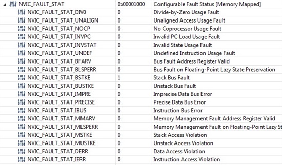
    I am posting NVIC registers content after fault. Kindly look at above comment for detailed problem.

    Regards

    Prashant

  • Hello Prashant,

    There is a Stack Bus Fault which would point to the Floating Point Unit not being enabled whose fault has causes an issue on the SP

    Regards

    Amit

  • Hii amit

    So now what should i do? I have no idea.

    Regards

    Prashant

  • Hello Prashant,

    As suggested earlier, please enable the FPU by calling

        FPUEnable();
        FPULazyStackingEnable();

    and including #include "driverlib/fpu.h"
    before doing any Floating point arithemetic. Also increase the Stack Size

    Regards

    Amit

  • hii amit

    i have already done these things. still getting error.

    regards

    prashant

  • Hello Prashant,

    Can you share your CCS project simplified to reproduce the error?

    Regards

    Amit

  • http://e2e.ti.com/cfs-file.ashx/__key/communityserver-discussions-components-files/908/8182.BLDC.c

    hii amit

    here is the link to project code.

    regards

    prashant

  • Hello Prashant,

    The code mentioned does not match the original post on where the issue is? Can you please check and update

    Regards

    Amit

  • Hii amit

    Initially i thought that the problem is with multiplication so i just posted a sample code piece similar to my code. main code is lenthy so to simplified i posted a piece where i had doubt. kindly go through full code mentioned later.

    thanks

    prashant

  • Hello Prashant,

    I ported the code over and it works fine. There is no Fault ISR. However do note that in the code you sent there is the interrupt handler for measuring the pulses, which will not get excited as my setup from the hw perspective is not the same as yours.

    Regards

    Amit

  • Amit Ashara said:
    I ported the code over and it works fine. There is no Fault ISR.

     Hi Amit, I got just now my daily Fault ISR, can I send you my code too ;)

     I ported Kentec driver to TIVA 123 LP, next I adapt to also run on BP socket 1 of 129 on same driver, but every time Fault ISR is forever behind the lines... Agghhhh!!

  • Hello Roberto

    Sure, why not :-)

    Regards

    Amit

  • Hiii amit

    yeah I know that Without enabling interrupt, code is working fine but as I enable interrupt, it goes into ISR. Please suggest some solution.

    Thanks

  • Hii amit.

    when i dont initiate inturrept , my code works fine. what may be the problem?

  • when i dont initiate inturrept , my code works fine. what may be the problem?

    Perhaps not having a handler implemented for this interrupt ?

    Or missed to clear the interrupt flag ?

    Or cleared the interrupt flag at the very last moment in the interrupt handler ?

  • Hii f.m. 

    problem is weird.

    1.when i use a multiplication(float) in that code with interrupt ENABLED, code goes to fault ISR.

    2.when i use a multiplication(float) in that code with interrupt DISABLED, code works fine.

    3. when i DONT use multiplication(float) in that code with interrupt ENABLED, code works fine.


  • Hello Prashant,

    That narrows it down to the multiplication in the interrupt handler. That is useful information for us to narrow down for you

    Regards

    Amit

  • Hi amit

    multiplication is not in the ISR. it is in main.

  • Hello Prashant,

    From your code... There is multiplication in the ISR as well.

    void PortBIntHandler(void){ //port B interrupt handler ISR. measuring frequency of signal at PB4 which is a hall signal PA6
      GPIO_PORTB_ICR_R = 0x10;      // acknowledge flag4
      Old_Count=New_Count;
        New_Count=TimerValueGet(TIMER0_BASE, TIMER_A);
        if(New_Count>Old_Count)
        {
        Elapsed_Count=New_Count-Old_Count;
        freq=79901869.00/Elapsed_Count;
        speed=(int)freq*15;
        }
    }

    Please note that I used your code only, and the only difference was since GPIO Port-B is not getting any input signal the Interrupt handler for the same is not being invoked. This I have already highlighted in one of my earlier posts.

    Regards

    Amit

  • Hii amit

    Yes there is a multiplication in ISR as well. I am sorry I ignored that multiplication because it is not creating any problem. 

  • Hii amit

    I have modified my code and avoided multiplication of float numbers. now everything working perfect.

    Thank you all people for devoting time. I am attaching final working code for "PI based Speed Control of BLDC motor" in case anyone need.

    thank you.

    #include <stdint.h>
    #include <stdbool.h>
    #include "inc/hw_gpio.h"
    #include "inc/hw_types.h"
    #include "inc/hw_memmap.h"
    #include "driverlib/sysctl.h"
    #include "driverlib/pin_map.h"
    #include "driverlib/gpio.h"
    #include "driverlib/pwm.h"
    #include "driverlib/adc.h"
    #include "driverlib/sysctl.h"
    #include<inc/tm4c123gh6pm.h>
    #include<driverlib/interrupt.h>
    #include<driverlib/timer.h>
    #include<driverlib/fpu.h>
    void PortBIntHandler(void);
    void PortBInit(void);
    void pwminit(void);
    volatile unsigned long ui32Loop,Count,duty_old,kpw,kiw;
    volatile unsigned long Old_Count,Elapsed_Count,a;
    volatile unsigned long New_Count=0;
    int speed_act,speed_ref,speed_error,speed_error_old,duty,duty1;
    float freq;
    unsigned long ulPeriod;
    volatile unsigned long ha,hb,hc,pwm;
    int main(void) {
    	     SysCtlClockSet(SYSCTL_SYSDIV_2_5 | SYSCTL_USE_PLL |   SYSCTL_OSC_MAIN | SYSCTL_XTAL_16MHZ); // setting system clock
    		 SysCtlPeripheralEnable(SYSCTL_PERIPH_GPIOD); // port ABDEF initialization
    		 SysCtlDelay(3);
    		 SysCtlPeripheralEnable(SYSCTL_PERIPH_GPIOE);
    		 SysCtlDelay(3);
    		 SysCtlPeripheralEnable(SYSCTL_PERIPH_GPIOA);
    		 SysCtlDelay(3);
    		 SysCtlPeripheralEnable(SYSCTL_PERIPH_GPIOF);
    		 SysCtlDelay(3);
    		 SysCtlPeripheralEnable(SYSCTL_PERIPH_GPIOB);
    		 	SysCtlDelay(3);
    		 	GPIOPinTypeGPIOInput(GPIO_PORTB_BASE,GPIO_PIN_4); //PB4 as speed signal input
    		 GPIOPinTypeGPIOOutput(GPIO_PORTD_BASE, GPIO_PIN_0|GPIO_PIN_1|GPIO_PIN_2|GPIO_PIN_3); // PD 0,1,2,3 as output
    		 GPIOPinTypeGPIOOutput(GPIO_PORTE_BASE, GPIO_PIN_1|GPIO_PIN_2);  //PE 1,2 as output
    		 GPIOPinTypeGPIOInput(GPIO_PORTA_BASE, GPIO_PIN_2|GPIO_PIN_5|GPIO_PIN_6|GPIO_PIN_7); // PA 2,5,6,7 as Input
    	    SysCtlPeripheralEnable(SYSCTL_PERIPH_TIMER0); //Timer 0 enable
    		SysCtlDelay(3);
    		TimerDisable(TIMER0_BASE,TIMER_A);
    		TimerConfigure(TIMER0_BASE, TIMER_CFG_PERIODIC_UP);
    		TimerLoadSet(TIMER0_BASE, TIMER_A, 0x00FFFFFF);
    		TimerEnable(TIMER0_BASE, TIMER_A);
    		FPUEnable(); // floating point unit enable
    		FPULazyStackingEnable();
    		ulPeriod = SysCtlClockGet() / 5000; //Time period for pwm signal for 5000Hz frequency
    		pwminit(); // PWM initialization
            PortBInit(); // initialize GPIO Port B interrupt
            speed_act=0;
            speed_error_old = 0.0;
            duty_old=0.99;
    while(1) {
    	speed_ref=5500;
    //	    	kpc=100;
    //	    	kic=1;
    	    	kpw=1;
    	    	kiw=0.05;
    	    	speed_error = speed_ref - speed_act;
    	        duty = (duty_old + kpw*(speed_error - speed_error_old) + kiw*speed_error);
    	        duty_old=duty;
    	        speed_error_old = speed_error;
    	duty1 = (int)(duty*100);
    	        if(duty1>100)
    	        {
    	        duty1 = 99;
    	        }
    	        else if(duty1<0)
    	        {
    	        duty1 = 1;
    	        }
    		       PWMPulseWidthSet(PWM1_BASE, PWM_OUT_5,duty1*ulPeriod/100); // pulse width updation
    	                   pwm=GPIOPinRead(GPIO_PORTA_BASE,GPIO_PIN_2) & 0x04; // reading pwm signal on PA2
                           ha=GPIOPinRead(GPIO_PORTA_BASE,GPIO_PIN_5) & 0x20; // PA 5,6,7 as hall signal input
    	   	        	   hb=GPIOPinRead(GPIO_PORTA_BASE,GPIO_PIN_6) & 0x40;
    	   	        	   hc=GPIOPinRead(GPIO_PORTA_BASE,GPIO_PIN_7) & 0x80;
    	   	        	if(pwm==0x04) // if pwm signal is 1
    	   	        	        {
    
    	   	        		if(ha==0x20 && hb==0x40 && hc!=0x80) //110 position
    	   	        		{
    	   	        		 GPIOPinWrite(GPIO_PORTD_BASE,GPIO_PIN_0, false);
    	   	        		 GPIOPinWrite(GPIO_PORTD_BASE,GPIO_PIN_1, false);
    	   	        		 GPIOPinWrite(GPIO_PORTE_BASE,GPIO_PIN_2, false);
    	   	        		 GPIOPinWrite(GPIO_PORTE_BASE,GPIO_PIN_1, false);
    	   	        		 GPIOPinWrite(GPIO_PORTD_BASE,GPIO_PIN_3, GPIO_PIN_3);
    	   	        		 GPIOPinWrite(GPIO_PORTD_BASE,GPIO_PIN_2, GPIO_PIN_2);
    	   	        		 }
    	   	        		else if(ha!=0x20 && hb==0x40 && hc!=0x80) //010 position
    	   	        		 {
    
    	   	        		 GPIOPinWrite(GPIO_PORTD_BASE,GPIO_PIN_0, false);
    	   	        		 GPIOPinWrite(GPIO_PORTD_BASE,GPIO_PIN_2, false);
    	   	        		 GPIOPinWrite(GPIO_PORTE_BASE,GPIO_PIN_1, false);
    	   	        		 GPIOPinWrite(GPIO_PORTE_BASE,GPIO_PIN_2, false);
    	   	        		 GPIOPinWrite(GPIO_PORTD_BASE,GPIO_PIN_1, GPIO_PIN_1);
    	   	        		 GPIOPinWrite(GPIO_PORTD_BASE,GPIO_PIN_3, GPIO_PIN_3);
    	   	        		 }
    	   	        		else if(ha!=0x20 && hb==0x40 && hc==0x80)  //011 position
    	   	        		 {
    	   	        		 GPIOPinWrite(GPIO_PORTD_BASE,GPIO_PIN_0, false);
    	   	        		 GPIOPinWrite(GPIO_PORTD_BASE,GPIO_PIN_2, false);
    	   	        		 GPIOPinWrite(GPIO_PORTD_BASE,GPIO_PIN_3, false);
    	   	        		 GPIOPinWrite(GPIO_PORTE_BASE,GPIO_PIN_1, false);
    	   	        		 GPIOPinWrite(GPIO_PORTD_BASE,GPIO_PIN_1, GPIO_PIN_1);
    	   	        		 GPIOPinWrite(GPIO_PORTE_BASE,GPIO_PIN_2, GPIO_PIN_2);
    	   	        		 }
    	   	        		else if(ha!=0x20 && hb!=0x40 && hc==0x80)  //001 position
    	   	        		 {
    	   	        		 GPIOPinWrite(GPIO_PORTD_BASE,GPIO_PIN_2, false);
    	   	        		 GPIOPinWrite(GPIO_PORTD_BASE,GPIO_PIN_1, false);
    	   	        		 GPIOPinWrite(GPIO_PORTD_BASE,GPIO_PIN_3, false);
    	   	        		 GPIOPinWrite(GPIO_PORTE_BASE,GPIO_PIN_1, false);
    	   	        		 GPIOPinWrite(GPIO_PORTD_BASE,GPIO_PIN_0, GPIO_PIN_0);
    	   	        		 GPIOPinWrite(GPIO_PORTE_BASE,GPIO_PIN_2, GPIO_PIN_2);
    	   	        		 }
    	   	        		else if(ha==0x20 && hb!=0x40 && hc==0x80)  //101 position
    	   	        		{
    	   	        		GPIOPinWrite(GPIO_PORTD_BASE,GPIO_PIN_1, false);
    	   	        		GPIOPinWrite(GPIO_PORTD_BASE,GPIO_PIN_2, false);
    	   	        		GPIOPinWrite(GPIO_PORTD_BASE,GPIO_PIN_3, false);
    	   	        		GPIOPinWrite(GPIO_PORTE_BASE,GPIO_PIN_2, false);
    	   	        		GPIOPinWrite(GPIO_PORTD_BASE,GPIO_PIN_0, GPIO_PIN_0);
    	   	        		GPIOPinWrite(GPIO_PORTE_BASE,GPIO_PIN_1, GPIO_PIN_1);
    	   	        		}
    	   	        		else if(ha==0x20 && hb!=0x40 && hc!=0x80)  //100 position
    	   	        		  {
    	   	        		GPIOPinWrite(GPIO_PORTD_BASE,GPIO_PIN_1, false);
    	   	        	    GPIOPinWrite(GPIO_PORTD_BASE,GPIO_PIN_0, false);
    	   	        		GPIOPinWrite(GPIO_PORTD_BASE,GPIO_PIN_3, false);
    	   	        		GPIOPinWrite(GPIO_PORTE_BASE,GPIO_PIN_2, false);
    	   	        		GPIOPinWrite(GPIO_PORTD_BASE,GPIO_PIN_2, GPIO_PIN_2);
    	   	        		GPIOPinWrite(GPIO_PORTE_BASE,GPIO_PIN_1, GPIO_PIN_1);
    	   	        			}
    	   	        		else
    	   	        		{
    	   	        		GPIOPinWrite(GPIO_PORTD_BASE,GPIO_PIN_0, false);
    	   	        	    GPIOPinWrite(GPIO_PORTD_BASE,GPIO_PIN_1, false);
    	   	        		GPIOPinWrite(GPIO_PORTE_BASE,GPIO_PIN_2, false);
    	   	        		GPIOPinWrite(GPIO_PORTE_BASE,GPIO_PIN_1, false);
    	   	        		GPIOPinWrite(GPIO_PORTD_BASE,GPIO_PIN_3, false);
    	   	        		GPIOPinWrite(GPIO_PORTD_BASE,GPIO_PIN_2, false);
    	   	        		}}
    	   	        		else
    	   	        	     {
    	   	        		 GPIOPinWrite(GPIO_PORTD_BASE,GPIO_PIN_0, false);
    	   	        		 GPIOPinWrite(GPIO_PORTD_BASE,GPIO_PIN_1, false);
    	   	        		 GPIOPinWrite(GPIO_PORTE_BASE,GPIO_PIN_2, false);
    	   	        		 GPIOPinWrite(GPIO_PORTE_BASE,GPIO_PIN_1, false);
    	   	        		 GPIOPinWrite(GPIO_PORTD_BASE,GPIO_PIN_3, false);
    	   	        		 GPIOPinWrite(GPIO_PORTD_BASE,GPIO_PIN_2, false);
    	   	        	     }
    }}
    
    void PortBInit(void){ // port B initialization for inturrept
    	GPIOIntTypeSet(GPIO_PORTB_BASE,GPIO_PIN_4,GPIO_FALLING_EDGE);
    	IntEnable(INT_GPIOB);
    	GPIOIntEnable(GPIO_PORTB_BASE, GPIO_INT_PIN_4);
    }
    
    void PortBIntHandler(void){ //port B interrupt handler ISR. measuring frequency of signal at PB4 which is a hall signal PA6
      GPIO_PORTB_ICR_R = 0x10;      // acknowledge flag4
      Old_Count=New_Count;
        New_Count=TimerValueGet(TIMER0_BASE, TIMER_A);
        if(New_Count>Old_Count)
        {
        Elapsed_Count=New_Count-Old_Count;
        freq=79901869.00/Elapsed_Count;
        speed_act=(int)freq*15;
        }
    }
    void pwminit() //PWM configure
    {
    	   SysCtlPWMClockSet(SYSCTL_PWMDIV_1);
    	    SysCtlPeripheralEnable(SYSCTL_PERIPH_PWM1);//The Tiva Launchpad has two modules (0 and 1). Module 1 covers the LED pins
    	    GPIOPinConfigure(GPIO_PF1_M1PWM5);
    	    GPIOPinTypePWM(GPIO_PORTF_BASE, GPIO_PIN_1);
    	    PWMGenConfigure(PWM1_BASE, PWM_GEN_2, PWM_GEN_MODE_UP_DOWN | PWM_GEN_MODE_NO_SYNC);
    	    PWMGenPeriodSet(PWM1_BASE, PWM_GEN_2, ulPeriod);
    	    PWMPulseWidthSet(PWM1_BASE, PWM_OUT_5,0.8*ulPeriod);
    	    PWMGenEnable(PWM1_BASE, PWM_GEN_2);
    	    PWMOutputState(PWM1_BASE, PWM_OUT_5_BIT, true);
    }
    

  • Hi,

    Since there are floating point operations including inside ISRs, then it is wise to increase the stack space. This is because each stack frame should be built with double number of registers. 

    As I wrote in a previous post, you can avoid such fp operations if using simply integers or working with engineering units, depends on your project. 

    Petrei

  • Hii petrei

    yeah you suggested the same. please guide me to increase stack size. I am unaware of it.

    thanks

  • Hi,

    Go to Project>Properties>Build>ARM Linker>Basic Optios tab and in the last fied, Set C system stack you can modify it.

    Petrei

  • Amit Ashara said:
    Sure, why not :-)

     Hi Amit, maybe I quit troubleshhoting if I cannot find reason why.. ( I am near that) but my goal is to pass finished work and a lot to do commentig and prepare new BP1 code require at almost 10 day of free time.

     To be tested Tm4c123 and c129 launchpad plus a Kitronix Boosterpak are needed to fully test code.

  • Prashant Surana said:
    modified my code and avoided multiplication of float numbers. now everything working perfect.

    Our tech group has (some) experience w/BLDC motors & LX4F (and ARM MCUs from others).  And StellarisWare 9453.

    Here some few observations:

    a) our belief - it's "normal/customary" when using the MCU's "PWM Generators" - to also call, "GPIOPinTypePWM()" for each/every of the six GPIO pins - encompassed by those PWM Generators.  We find just ONE such call - and that to a pin "not part" of your targeted BLDC outputs!  (instead to PF1 - likely a Led!)

    b) BLDC motors run under digital Hall sensors (as opposed to analog Halls or proper encoder) are unlikely to benefit (at all) from the added complexity of, "floating point."  Using just integer arithmetic - with several of the methods described by poster Petrei - we've long been able to achieve better than 1% speed or power regulation - using Hall sensors.  Under favorable conditions - our PID loop is able to exceed 0.1% speed/power regulation - again floating point is not used.

    c) It's far more classic to "count & then compute" the motor's speed via simple processing of the hall signal inputs alone.  You employ a separate port (A) and pin to do so - seems w/out much merit.  (again - we've achieved 0.1% speed/power regulation - using just the harvested hall signal data.) 

    Our findings of such 1% (or better) regulation are based upon our use of the hall signals AND a 2,048 "capacitive based" motor encoder - outputting to a separate MCU.  The encoder serves as our "gold standard" - and our 1% claim is based upon comparison between our hall results and those of this encoder.  (encoder just for "test/verify" during development)

    d) Code submitted includes a single call to, "PWMGenConfigure(PWM1_BASE, PWM_GEN_2...)" which we believe "not" to be fully adequate to enable proper PWM for 3 PWM Generators!  (we'd expect to see 3 such calls - for a 3 phase motor...)

    e) That (single) "PWMGenConfigure(PWM1_BASE, PWM_GEN_2...)" call uses parameter, "PWM_GEN_MODE_NO_SYNC" while most BLDC applications benefit from some form of PWM Sync.

    f) No use (nor mention) of "Deadband" appears.  Might the safety provided by "deadband" be worthwhile?  (Ans: of course!)

    g) Vendor's PWM Generators include a powerful, "PWM_Fault_Pin" which enables a pure hardware "shut-down" of the PWM during a "danger" condition.  Beyond that safety - transient over-loads may be detected - and "cleared" via clever use of that pin.  It's nowhere to be found - your code.

    There are many (other) standard requirements for successful BLDC motor control.  Cycle by cycle current/power limiting, graceful recovery from transient current/power spikes, and varied BLDC motor Acceleration/Deceleration - so that the BLDC may follow client's desired, "Motion Profile."  It's also likely that N-FETs are considered (due to efficiency & cost savings) and these normally require gate-drivers to "boost" the High-Side FETs' Gates beyond the applied motor voltage - so that the FET may properly/fully conduct.

    Our group advises some "caution" - and consideration of the points raised herein - prior to others implementing poster's code w/a real, 3 phase, BLDC motor...

    It's quite good that poster made the time/effort to post his code - he deserves thanks & appreciation.  This post aims to benefit both poster & others - landing this thread - and is intended to encourage further thought & investigation - and to (possibly) improve poster's (and others') BLDC motor operation...

  • Amit Ashara said:
    Sure, why not :-)

     Hi Amit, issue caught and filed too on your stick about fault isr, it was not so immediate after porting code from 129 back to 123. ;)

     Again issue I suggest modify your sticky in a different graphics manner so center or justify left and highlight 123 processor then list port patch, same for 129: more incisive and indented on group ready to cut and paste:

    TM4C123 processor Devices:

    // Port-C unlock

    HWREG(GPIO_PORTC_BASE+GPIO_O_LOCK) = GPIO_LOCK_KEY;

    HWREG(GPIO_PORTC_BASE+GPIO_O_CR) |= (GPIO_PIN_0|GPIO_PIN_1|GPIO_PIN_2|GPIO_PIN_3);

    // Port-D unlock

    HWREG(GPIO_PORTD_BASE+GPIO_O_LOCK) = GPIO_LOCK_KEY;

    HWREG(GPIO_PORTD_BASE+GPIO_O_CR) |= GPIO_PIN_7;

    // Port-F unlock

    HWREG(GPIO_PORTF_BASE+GPIO_O_LOCK) = GPIO_LOCK_KEY;

    HWREG(GPIO_PORTF_BASE+GPIO_O_CR) |= GPIO_PIN_0;

    TM4C129 Processor Devices

    // Port-C unlock

    HWREG(GPIO_PORTC_AHB_BASE+GPIO_O_LOCK) = GPIO_LOCK_KEY;

    HWREG(GPIO_PORTC_AHB_BASE+GPIO_O_CR) |= (GPIO_PIN_0|GPIO_PIN_1|GPIO_PIN_2|GPIO_PIN_3);

    // Port-D unlock

    HWREG(GPIO_PORTD_AHB_BASE+GPIO_O_LOCK) = GPIO_LOCK_KEY;

    HWREG(GPIO_PORTD_AHB_BASE+GPIO_O_CR) |= GPIO_PIN_7;

    // Port-F unlock

    HWREG(GPIO_PORTF_AHB_BASE+GPIO_O_LOCK) = GPIO_LOCK_KEY;

    HWREG(GPIO_PORTF_AHB_BASE+GPIO_O_CR) |= GPIO_PIN_0;


  • cb1_mobile said:

    b) BLDC motors run under digital Hall sensors (as opposed to analog Halls or proper encoder) are unlikely to benefit (at all) from the added complexity of, "floating point."  Using just integer arithmetic - with several of the methods described by poster Petrei - we've long been able to achieve better than 1% speed or power regulation - using Hall sensors.  Under favorable conditions - our PID loop is able to exceed 0.1% speed/power regulation - again floating point is not used.

     Hi CB1, this point is very interesting but remember when all is M$ centered and all people cry of their poor math knowledge beetter to use more power than optimize then all go to bad spoken is more simple to use power float than do complex integer calculation!! This is when somene don't know what is under the hood!

     Again they don't understand how FP is implemented nor precision can be much lesser than integer calculation, so I am not able to fully grasp FP examples from TI  using FP to regulate a PWM led, I am tuned on how to use on his integer domain and still this remain integer due to his nature so Sine cosine remain locked to my experience and knowledge of integer regulation like your.

     Are the new generation same to all ready precooked?? (so as on my opening talk)

     Again using intermixed FP and INT math require full depth knowledge of both, precision of FP about significant or coefficient or  mantissa defining how much bit and consequently precision belong to this implementation,  and what assigned to exponent or equivalent to characteristic term from logarithm lead to magnitude of span of smallest and biggest number. Again lack of school base is spreading this imprecision on and magnitude of FP tend to be confused with precision resolution or significative number of digit.

     I agree but when FP can be of real help we can use otherwise all our experience and knowledge get lost forever and FP still need Integer knowledge due they under the hood are integer too!

    cb1_mobile said:
    f) No use (nor mention) of "Deadband" appears.  Might the safety provided by "deadband" be worthwhile?  (Ans: of course!)

     I use dead band when I need it, most PWM bridge controller set themselves dead band and simple phase drive can be enough if you don't open bridge in the middle to for example measure the BEMF  prevalently on DC motor to evaluate speed.

  • Bonjourno Roberto,

    You make (as usual) many good points.  And on the whole I agree.

    Yet - my post attempted to alert new readers that the claim of, "Worked perfectly" may benefit from some "peer review" - and that more examination & testing may be required before "new users" attach their expensive BLDC to that "perfect code."

    When sine/cosine is required - floating point is (usually) demanded.  But poster's (basic) BLDC implementation does not rise that high - and surely integer math would more than suffice.  Again - we regularly achieve better than 1% speed/power accuracy - and floating point does not "darken" our code's doorstep. 

    I detailed multiple points for poster's (and follow on - BLDC users) benefit - yet the post is SO poorly titled (Fault ISR) that no one will EVER find it!  Oh well - thinking to the "benefit of others" does not rise as high as you/I desire - and vendor fails to accept your/my guidance - which would assist posters - and create a better forum experience for all.  (they surely know best!)

  • Hello Roberto

    Thanks for the sticky post update and clarity on the data sheet line. It should have been made very clear by stating that "may be accessed" to "can only be accessed"

    Regards

    Amit

  • Amit Ashara said:

    "may be accessed" to "can only be accessed"

     One more line added, plan if set on first line, check clock and dont OVERCLOCK!!! Processor behave unpredictable and remain trapped in systimer

     The last hint use tivaware instead can be forwarded to who wrote Kentec driver ?? :((( arghhhh I am near finishing polish all bad things then I can start unify drivers...