This thread has been locked.

If you have a related question, please click the "Ask a related question" button in the top right corner. The newly created question will be automatically linked to this question.

Tiva C series starting up.

Other Parts Discussed in Thread: TM4C123GH6PM, EK-TM4C123GXL

Hello Guys. I just received my Tiva C Series TM4C123G Dev Board.

Following the video tutorial on youtube  I wasn't able to make my led blinking. I understand that the memory map of the Tiva kit is different from the Stellaris one, but I changed the addresses accordingly the datasheet for TM4C123GH6PM. So there the Data Register for Port F is at different address. I changed the pointers to addresses according the datasheet, and yet my RED LED doesn't flash. Here is my code:

int main()
{
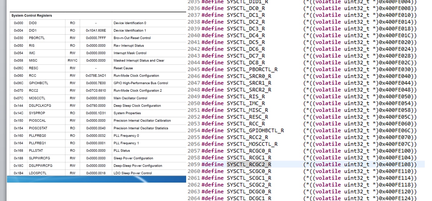
*((unsigned int *)0x400FE608U) = 0x20U; //Clock Gating address____allow clock sourcing for port F
*((unsigned int *)0x40025400U) = 0x0EU; //Port Direction____Set port F pins 1,2,3 as outputs
*((unsigned int *)0x400255C1U) = 0x0EU; //Digital Enable___Set port F pins 1,2,3 as digital I/O
*((unsigned int *)0x40025000U) = 0x02U; //Data Register___shuld set the red LED
  return 0;
}

The adjustments of my the Debugger are OK since I  successfully detected and ran the Board in Debug mode. 

Thank you in advance.

  • Hello Radoslav

    Please refer to the troubleshooter post You may have the answer on the first line of the code.

    http://e2e.ti.com/support/microcontrollers/tiva_arm/f/908/t/374640.aspx

    Regards

    Amit

  • Do you have any reason to program in direct register, with actual values (no macros) ?

    If not i advise using TivaWare to program.

  • Because when I use the Tiva's workspace I am not able to use my Tiva board as a debuger. Selected debuger is a simulator but not Tiva TM4C123G board, that I am trying to use. May be you can help me to change the debuger into the so called Blinky project. These are my first steps in programming and I am not familiar with how to use the premade projects from the Tiva ware directoryes.

    Thank you for the answers.

    Excuse my bad English.

  • Hello Radoslav

    Your new post seems to be in conflict with the first one. However we can still get it going.

    1. Have you downloaded and installed full TivaWare-2.1.0-12573?

    2. Which IDE are you using? If it is CCS then, you can Import one of the existing projects from the installed TivaWare which in default will be kept at

    C:\ti\TivaWare_C_Series-2.1.0.12573\examples\boards\ek-tm4c123gxl

    How to Import? Well on opening CCS, File -> Import -> Code Composer Studio (expand) -> Existing CCS Eclipse Projects (Click Next)

    In Select Search-directory use the path mentioned above and it will list the projects. Select the project you want to run "in this case blinky" and Click Finish.

    Once done, then Build the Project and click on debug button to load the same to the board.

    If I may have gone too deep or too off topic then do correct me...

    Regards

    Amit

  • Thank you dear Amit,

    1. Yes I have.

    2. I haven't decided which one to use yet. I managed to run the "Blinky" project on CCS, thanks to your help.

    Now I am trying to understand what I actually did :)

    Here is an example:

    This SYSCTL_RCGC2_R is at address 0x400FE108 according to the "tm4cgh6pm.h" and has something to do with System Control registers. The problem is that I can't find such address in the datasheet in order to understand its purpose.

    There are other macros for registers with addresses that doesn't exist in the datasheet.

  • Notice that blinky doesn't use the TivaWare APIs, it uses direct register access.

    Never use register access unless you really need fast code or the function doesn't exist in TivaWare. With direct register access you can do whatever you want and there are no safeguards like TivaWare functions have. I advise using them for faster and safer coding, and then go look into the source files to learn more about the registers, if you need to use them.

    To look for SYSCTL_RCGC2_R, try to search for RCGC2 in 5.4 Register Map in the datasheet. Being SYSCTL it means it's a registe from system control. In the datasheet that is the title: 5 System Control.

    Check this out if you are starting with TivaWare, it usually doesn't go into much detail about the registers since the people to who i have made that blog still haven't gotten into that yet (in detail at least)

     https://sites.google.com/site/luiselectronicprojects/tutorials/tiva-tutorials

  • I made this, since i had to make it to my friends that know nothing about registers, it uses blinky example to explain a bit about the registers and how to search their description on the datasheet.

    https://sites.google.com/site/luiselectronicprojects/tutorials/tiva-tutorials/direct-register-access-notes/how-to-find-registers---1

    What do you think Amit? :p

  • Hello Radoslav,

    The RCGC2 register is a legacy register in System Control Module and would be in a second table just after the one you pasted. Simply: Search for 0x108 in the System Control Module section of the data sheet.

    Coming to the original code, you enabled the RCGCGPIO (which is the preferred mehcanism) bit for Port-F. However it takes time for the clock to be enabled and you should have put a delay loop before accessing the GPIO Port-F register.

    Regards

    Amit

  • Hello Luis,

    I appreciate the site that you have created (and as one of your previous posts confirmed by Dave Maples) and it is a good informative site especially considering that learning a new device is never easy. Something that our data sheets miss, you have started filling in the "critical" gaps. Also your point is extremely good on DRM. It should be least used approach for beginners.

    A sincere Thanks...

    Regards

    Amit

  • Thank you Guys.
    Amit you pointed out that my miss is the delay loop that gives some time to the processor to enable the PORTF clock. OK in my code the address of the PORTF data register is 0x40025000, but the macro for that register in the tm4c123gh6pm.h is different 0x400253FC. I am not very good in finding registers in the datasheet, thats why I ask you for help.


  • Hi Radoslav,

    Check 10.2.1.2 Data Register Operation on the datasheet. I'll leave the deduction to you since you are learning.

    Come back if you can't figure out the reason

  • Hello Radoslav,

    The header file only gives the full address for each register in each peripheral instance. To get to the correct register in the data sheet, you must go to the section for it. For example in this case GPIO Section. In the table the register offset (last 12-bits of the address) is given. The base address 32-bit is given just before the table and before every register description. An addition of the same will give you the full 32-bit addtess for the register in a particular peripheral instance,

    Just to be clear: A peripheral can have multiple instances... For example GPIO has Port A, B, C.... and so on. So even though the peripheral is 1, the instances are N.

    Regards

    Amit

  • Thank you both.

    I understand now. I thought that one register controls the entire PORT_F data bits, but indeed there are 256 different addresses that correspond to different bit masking of the port. I succeeded to blink the LEDs on both CCS and IAR and I am very happy thanks to you. My next step is to handle the inputs using the user on-board buttons.

  • I'm glad you have been clarified 

    good luck with studying how to use the Tiva