This thread has been locked.

If you have a related question, please click the "Ask a related question" button in the top right corner. The newly created question will be automatically linked to this question.

I2C 'Sniffer' Detects Devices At All Addresses

Other Parts Discussed in Thread: TMP100, EK-TM4C123GXL, EK-TM4C1294XL

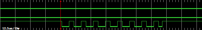
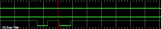
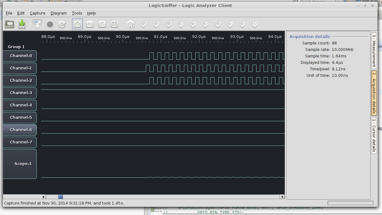
I have been trying for several hours to get a simple I2C circuit setup with the TM4C123GXL board and an MCP23017 IO Expander. I've looked at many forum posts about I2C problems with this board, but none have helped. Currently I'm using code from http://e2e.ti.com/support/microcontrollers/tiva_arm/f/908/t/235977.aspx for the I2C setup and address scanning (it loops through addresses from 0 to 127 and tests if they acknowledge):

void I2CSetup(void) {
		//enable I2C module 0
		ROM_SysCtlPeripheralEnable(SYSCTL_PERIPH_I2C0);
		//enable GPIO peripheral that contains I2C 0
		ROM_SysCtlPeripheralEnable(SYSCTL_PERIPH_GPIOB);

		//reset module		ROM_SysCtlPeripheralReset(SYSCTL_PERIPH_I2C0);

		// Configure the pin muxing for I2C0 functions on port B2 and B3.
		ROM_GPIOPinConfigure(GPIO_PB2_I2C0SCL);
		ROM_GPIOPinConfigure(GPIO_PB3_I2C0SDA);

		// Select the I2C function for these pins.
		ROM_GPIOPinTypeI2CSCL(GPIO_PORTB_BASE, GPIO_PIN_2);
		ROM_GPIOPinTypeI2C(GPIO_PORTB_BASE, GPIO_PIN_3);

		// Enable and initialize the I2C0 master module.  Use the system clock for
		// the I2C0 module.  The last parameter sets the I2C data transfer rate.
		// If false the data rate is set to 100kbps and if true the data rate will
		// be set to 400kbps.
		ROM_I2CMasterInitExpClk(I2C0_BASE, SysCtlClockGet(), false);

		//clear I2C FIFOs
		HWREG(I2C0_BASE + I2C_O_FIFOCTL) = 80008000;
	}
unsigned long
I2CBusScan(unsigned long ulI2CBase)
{
	unsigned char ucProbeAdress;
	unsigned long ucerrorstate;

	//
	// Check the arguments.
	//
	ASSERT(I2CMasterBaseValid(ulI2CBase));

	//
	// Wait until master module is done transferring.
	//
	while(ROM_I2CMasterBusy(ulI2CBase))
	{
	};

	//
	// I2C Addresses are 7-bit values
	// probe the address range of 0 to 127 to find I2C slave devices on the bus
	//
	for (ucProbeAdress = 0; ucProbeAdress < 127; ucProbeAdress++)
	{
	    //
	    // Tell the master module what address it will place on the bus when
	    // writing to the slave.
	    //
		ROM_I2CMasterSlaveAddrSet(ulI2CBase, ucProbeAdress, false);
	    ROM_SysCtlDelay(50000);

	    //
	    // Place the command to be sent in the data register.
	    //
	    ROM_I2CMasterDataPut(ulI2CBase, 0x00);

	    //
	    // Initiate send of data from the master.
	    //
	    ROM_I2CMasterControl(ulI2CBase, I2C_MASTER_CMD_BURST_SEND_START);

	    //
	    // Make some delay
	    //
	    ROM_SysCtlDelay(500000);

	    //
	    // Read the I2C Master Control/Status (I2CMCS) Register to a local
	    // variable
	    //
	    ucerrorstate = ROM_I2CMasterErr(ulI2CBase);

	    //
	    // Examining the content I2C Master Control/Status (I2CMCS) Register
	    // to see if the ADRACK-Bit (Acknowledge Address) is TRUE (1)
	    // ( 1: The transmitted address was not acknowledged by the slave)
	    //
	    if(ucerrorstate & I2C_MASTER_ERR_ADDR_ACK)
	    {
	    	//
	    	// device at selected address did not acknowledge --> there's no device
	    	// with this address present on the I2C bus
	    	//
	        //
	        // Print a message to Stdio
	        //
	    	//UARTprintf("Address not found: 0x%2x - %3d\n",ucProbeAdress,ucProbeAdress);
		    //
		    // Make some delay
		    //
	    	//ROM_SysCtlDelay(1500000);
	    }

	    //
	    // ( 0: The transmitted address was acknowledged by the slave)
	    //
	    else
	    {
	    	//
	    	// device at selected address acknowledged --> there is a device
	    	// with this address present on the I2C bus
	    	//
	        //
	        // Print a message to Stdio
	        //
	    	UARTprintf("Address found: 0x%2x - %3d\n",ucProbeAdress,ucProbeAdress);

		    //
		    // Make some delay
		    //
	    	ROM_SysCtlDelay(1500000);
	    }
	}

	//
	// End transfer of data from the master.
	//
	ROM_I2CMasterControl(ulI2CBase, I2C_MASTER_CMD_BURST_RECEIVE_FINISH);

    //
    // Print a message to Stdio
    //
	UARTprintf("I2C Bus-Scan done...\n");

    //
    // Return 1 if there is no error.
    //
    return 1;
}

For some reason, the program reports that there is a device at every address from 0 to 127 (ie ROM_I2CMasterErr always returns 0), even though I only have one. I have 4k7 pull-up resistors on SCL and SDA and several 0.1uF bypass caps. The reset pin is also connected to 5V (active-low). Any ideas what could be wrong?

  • Ari Croock said:
    For some reason, the program reports that there is a device at every address from 0 to 127 (ie ROM_I2CMasterErr always returns 0), even though I only have one. I have 4k7 pull-up resistors on SCL and SDA and several 0.1uF bypass

     At first glance code seems ok, try remove everything from I2C bus and see if still all addresses answer with ack, I don't know your device but after that try reset device before to scan, an RC to reset pin is better than direct wire to power rail.

     If removing all from bus don't ack all and still after resetting device respond to all addresses check another different device, if this work  the chip are you using maybe defective.

  • Hello Ari,

    Some general feedback besides Roberto's analysis

    1. You have mentioned TM4C123 device, yet the code seems to have a I2C_0_FIFOCTL register write which is an invalid write (though it may not be the issue here).

    2. Be aware that TM4C123 TivaWare API SysCtlClockGet has an issue if the System Clock is programmed for 80Mhz. The reported value will be 66MHz and may affect the Baud Rate

    3. It will be a good idea to scope the bus... I have seen it helping innumerable number of times for I2C.

    Regards

    Amit

  • Feel poster's pain.  Yet - 7 years past - we used that exact I2C IC to yield 16 "extra" GPIO via the I2C bus - using LM3S3xx under StellarisWare.  So - it CAN work!

    I note the absence of, "while(ROM_I2CMasterBusy(I2Cx_MASTER_BASE)) {}."  Poster employs fixed (guessed?) delays - never as effective as StellarisWare's, "tried/true" function call.

    The fact that "all addresses" register may indicate a program/code flaw - more than a slave device - is the culprit.  I'm in disbelief that a valid "ACK" is being returned - for each/every I2C address emitted!  No way!

    Scope is indeed helpful yet not universally available. 

    As Amit notes - so often does I2C "over-challenge" - that some "non-Scope" diagnostic methods should be identified and/or created.  Might PC diagnostic programs exist and be listed here?  Might small, inexpensive, I2C hardware/software diagnostic tools/boards exist - or be created - to assist basic (non scope equipped) users - and also listed?  Should not vendor here - rather than simple outsider - recognize & provide (list) such aids?  (we note there's time/energy to "rename the forum" (linked below) - never enough to provide the greatly needed I2C diagnostics just listed...)

    http://e2e.ti.com/support/microcontrollers/stellaris_arm/f/471/t/380810.aspx  (found in "death valley" aka Stellaris forum...)

    Appears there's an "unmet need" which has long lingered.  (I2C challenged many during LMI days - long past - little has changed...)

  • The same thing happens if I completely disconnect SCL and SDA, so it probably is a software problem.

    I tried changing all the delays to while(ROM_I2CMasterBusy(I2Cx_MASTER_BASE)) {} and all that changes is the scan runs faster.

    I did manage to setup my Pickit3 as a basic logic analyser, but being a PIC-related product, it randomly stopped working. I got a couple of traces though:

    SCL:

    SDA

  • You win great points for resourcefulness - I "knew" it was not slave device issue.  Love your use of that "enfeebled" other MCU to (practically) sniff the I2C bus - good job.  W/out a scope you're pretty much hopeless - your creation of a, "scope-lite" provides very needed insight.  Suggest that you experiment bit more - get your diagnostic device working.  Ideally you want to view SCL & SDA under the same time-base - the 2 traces you provide don't (clearly) reveal that.  I'd keep working - you want to confirm the Slave's ACK - then all should be well!  (review which bit is first/last w/in I2C protocol - in case unclear)  You need to positively confirm that the MCU emits the proper Slave Address for the slave to be able to ACK.

    Note I supplied I2Cx - of course you must adapt x to your specific usage.

    May I suggest that you "abandon" the (new) call to "addresses on bus" - and simply try (first) just to write to one Slave register.  Somewhere I've got our 7 year old code - under StellarisWare - and both LM3S & your slave I2C port expander worked flawlessly.  (must do some "real work" pay some bills - do press on & if time/strength allows I'll find/post our ancient code...)

    Many, many here "butcher" the 7 bit I2C Slave Address.  Recall that the MCU inserts the lsb (either read or write) you must thus place the 7 bit slave address w/a one bit offset.  (left I believe)  Use of the proper "Master Busy" check and bit more persistence - surely you'll succeed.   Bon chance mon ami....

  • cb1_mobile said:
    As Amit notes - so often does I2C "over-challenge" - that some "non-Scope" diagnostic methods should be identified and/or created.  Might PC diagnostic programs exist and be listed here?  Might small, inexpensive, I2C hardware/software diagnostic tools/boards exist - or be created - to assist basic (non scope equipped) users - and also listed? 

     Hi CB1, as I wrote in the past the better I found is Saleae Logic, serial protocol, Linbus, CANbus and I2C and SPI too plus other HW protocols ready to use. Nowaday Saleae changed product lines integrating a scope too, I loved logic and software too, quality got better but price increased consequently but still this product is better than expensive parts.

     In the lowest cost arena an MSP430 contest won with a low bandwidth analog/logic scope, see here:

     In the 2007 an I2C analyzer was presented @ over 3000€ so I built a logic analyzer like onto FPGA interfaced to network thru MSP430, this instrument  analyze all I2C transaction and timing extracting data too, I think all this can be feasible on a TM4C1294 in software only now but at Saleae price you can buy a better instrument. Maybe some low cost can be built around Tiva analog and digital too then interfaced to free software project but forever a ready to go product still is better.

    http://hackaday.com/2012/07/09/logic-analyzer-add-on-for-the-msp430-launchpad/

    http://www.prnewswire.com/news-releases/pocket-oscilloscope-scoops-first-place-in-msp430-ez-design-contest-56430787.html

    https://www.saleae.com

     Also check for discounts to university or special offer too.

  • Hello Ari,

    Might I suggest replacing I2C_MASTER_CMD_BURST_SEND_START with I2C_MASTER_CMD_SINGLE_SEND and then checking the bus-scan. Also comment out the line in the code which has

      ROM_I2CMasterControl(ulI2CBase, I2C_MASTER_CMD_BURST_RECEIVE_FINISH);

    Regards

    Amit

  • Hello Roberto,

    Nice!!! My rpoject-X has been declassified, as a DK-TM4C129 based LA was one of the proposed idea for on-field debug... May be a lower cost EK-TM4C129 would be more suitable with a Laptop.

    Regards

    Amit

  • Amit Ashara said:

    Nice!!! My rpoject-X has been declassified, as a DK-TM4C129 based LA was one of the proposed idea for on-field debug... May be a lower cost EK-TM4C129 would be more suitable with a Laptop.

     Amit I own an HP16500C and an Agilent 16702 and i think never upgrade due to I prefer UNIX based instrument and I hate having windoze on it but forever I prefer small LOGIC Saleae for protocol analising. Also one more plus where it can stay on laptop bag too.

     TM4c1294 can be used too, I suppose a better way can be with FPGA and ram board but I suppose @120MHz clock it can do best, question is display software, has a great advantage of galvanic isolation done using network and this is my primary goal to do some alternative, if you got time got an eye here:

    http://sigrok.org/

     Maybe we can od some work together if I solve fault isr issues too :( Again !

  • I tried replacing the bus scan function with this:

    I2CMasterSlaveAddrSet(I2C0_BASE, 0x54, true);
    I2CMasterDataPut(I2C0_BASE, 0x00);
    I2CMasterControl(I2C0_BASE, I2C_MASTER_CMD_SINGLE_SEND);
    while(I2CMasterBusy(I2C0_BASE)){};

    But there is no change. I chose the address as 0x54 because in binary the bits alternate, but there are still only two edges in the SDA waveform.


    BTW I was considering getting either a Bus Pirate or an Open Bench Logic Sniffer, but they are quite badly overpriced here in South Africa due to courier costs (our postal service is... broken).

  • Hello Ari,

    Let me check the code you posted on a TM4C123 LauchPad to see if I can get it to work as you are expecting.

    Indeed LA's and scope are some items that have a range of price-feature-availability. The last one I ordered as a low cost LA turned out to be a non-low cost after shipping.

    Regards

    Amit

  • Ari Croock said:
    BTW I was considering getting either a Bus Pirate or an Open Bench Logic Sniffer, but they are quite badly overpriced here in South Africa due to courier costs (our postal service is... broken).

     Are you belonging to school in some way? If so contact saleae and try special offer.

     Otherwise 99US$ for a 1 scope plus 4 logic channel is a good starting point for an instrument.

     This issue sound strange, sda is present also with just the Pullup and nothing on bus?

     Check i2c register and see what happen stepping code.

     TIVA can also be used to do diagnosis sampling two input and writing to memory clocked by a timer or better by edge on line then writing timer value event, this sort of small limited LA can help a lot.

  • Hello Roberto,

    Thanks for the link. It seems BBB is already there. Looking at the link and instrumentation, it may just be a mega project on TM4C129. KISS is my objective and may be we can discuss the details off the main thread.

    I need to get Ari running on this thread.

    Regards

    Amit

  • Amit Ashara said:

    I need to get Ari running on this thread.

    Indeed you do - and all 3 of us have pitched in - tried to aid poster Ari.

    But - as the reporter who, "fire-bombed" this thread w/request for (clearly, much needed) I2C diagnostic tools/methods - is not the, "expansion of this thread to the "Greater Good" of MANY" of some importance? 

    Repeated dealings with the same (ongoing) issues bores & eats time/effort - never good.  (and yet - minus the suggested diagnostics/User Self-Help - can only (endlessly) continue - frustrating users - reducing Sales...)

    Kudos to Roberto (especially) for his listings - and also to Amit for contributing.  This forum is quite good - yet too often past issues are "allowed" to linger - yet hallowed, "Forum Name Change" rises in priority - steals time/resources - seems very much miscast!

  • I did find this: http://nathan.chantrell.net/20130207/using-the-stellaris-launchpad-as-a-logic-analyser/

    and others but I could never get it to work properly.

    Also I am at a university so I emailed Saleae; we'll see what they say.

  • Hello Ari

    I took the code and the updates that you made and ran it on my EK-TM4C123 LP. It works fine and reports Address not found for an unconnected bus. However, I am using the internal Pull Up of the IO (which is ~30K) instead of using the 4K7 as you mentioned. Can you do the same?

    #include <stdbool.h>
    #include <stdint.h>
    #include "inc/hw_gpio.h"
    #include "inc/hw_i2c.h"
    #include "inc/hw_memmap.h"
    #include "inc/hw_types.h"
    #include "driverlib/gpio.h"
    #include "driverlib/i2c.h"
    #include "driverlib/rom.h"
    #include "driverlib/rom_map.h"
    #include "driverlib/pin_map.h"
    #include "driverlib/sysctl.h"
    #include "driverlib/uart.h"
    #include "utils/uartstdio.h"
    
    //*****************************************************************************
    //
    // This function sets up UART0 to be used for a console to display information
    // as the example is running.
    //
    //*****************************************************************************
    void
    InitConsole(void)
    {
        //
        // Enable GPIO port A which is used for UART0 pins.
        // TODO: change this to whichever GPIO port you are using.
        //
        SysCtlPeripheralEnable(SYSCTL_PERIPH_GPIOA);
    
        //
        // Configure the pin muxing for UART0 functions on port A0 and A1.
        // This step is not necessary if your part does not support pin muxing.
        // TODO: change this to select the port/pin you are using.
        //
        GPIOPinConfigure(GPIO_PA0_U0RX);
        GPIOPinConfigure(GPIO_PA1_U0TX);
    
        //
        // Enable UART0 so that we can configure the clock.
        //
        SysCtlPeripheralEnable(SYSCTL_PERIPH_UART0);
    
        //
        // Use the internal 16MHz oscillator as the UART clock source.
        //
        UARTClockSourceSet(UART0_BASE, UART_CLOCK_PIOSC);
    
        //
        // Select the alternate (UART) function for these pins.
        // TODO: change this to select the port/pin you are using.
        //
        GPIOPinTypeUART(GPIO_PORTA_BASE, GPIO_PIN_0 | GPIO_PIN_1);
    
        //
        // Initialize the UART for console I/O.
        //
        UARTStdioConfig(0, 115200, 16000000);
    }
    
    unsigned long
    I2CBusScan(unsigned long ulI2CBase)
    {
        unsigned char ucProbeAdress;
        unsigned long ucerrorstate;
    
        //
        // Wait until master module is done transferring.
        //
        while(ROM_I2CMasterBusy(ulI2CBase))
        {
        };
        //
        // I2C Addresses are 7-bit values
        // probe the address range of 0 to 127 to find I2C slave devices on the bus
        //
        for (ucProbeAdress = 0; ucProbeAdress < 127; ucProbeAdress++)
        {
            //
            // Tell the master module what address it will place on the bus when
            // writing to the slave.
            //
            ROM_I2CMasterSlaveAddrSet(ulI2CBase, ucProbeAdress, false);
    
            //
            // Place the command to be sent in the data register.
            //
            ROM_I2CMasterDataPut(ulI2CBase, 0x00);
    
            //
            // Initiate send of data from the master.
            //
            ROM_I2CMasterControl(ulI2CBase, I2C_MASTER_CMD_SINGLE_SEND);
    
            //
            // Make some delay
            //
            while(ROM_I2CMasterBusy(ulI2CBase));
    
            //
            // Read the I2C Master Control/Status (I2CMCS) Register to a local
            // variable
            //
            ucerrorstate = ROM_I2CMasterErr(ulI2CBase);
    
            //
            // Examining the content I2C Master Control/Status (I2CMCS) Register
            // to see if the ADRACK-Bit (Acknowledge Address) is TRUE (1)
            // ( 1: The transmitted address was not acknowledged by the slave)
            //
            if(ucerrorstate & I2C_MASTER_ERR_ADDR_ACK)
            {
                //
                // device at selected address did not acknowledge --> there's no device
                // with this address present on the I2C bus
                //
                //
                // Print a message to Stdio
                //
                UARTprintf("Address not found: 0x%2x - %3d\n",ucProbeAdress,ucProbeAdress);
                //
                // Make some delay
                //
                //ROM_SysCtlDelay(1500000);
            }
            //
            // ( 0: The transmitted address was acknowledged by the slave)
            //
            else
            {
                //
                // device at selected address acknowledged --> there is a device
                // with this address present on the I2C bus
                //
                //
                // Print a message to Stdio
                //
                UARTprintf("Address found: 0x%2x - %3d\n",ucProbeAdress,ucProbeAdress);
                //
                // Make some delay
                //
                ROM_SysCtlDelay(1500000);
            }
        }
    
        //
        //
        // Print a message to Stdio
        //
        UARTprintf("I2C Bus-Scan done...\n");
        //
        // Return 1 if there is no error.
        //
        return 1;
    }
    
    void I2CSetup(void)
    {
            //enable I2C module 0
    		ROM_SysCtlPeripheralReset(SYSCTL_PERIPH_I2C0);
            ROM_SysCtlPeripheralEnable(SYSCTL_PERIPH_I2C0);
            //enable GPIO peripheral that contains I2C 0
            ROM_SysCtlPeripheralEnable(SYSCTL_PERIPH_GPIOB);
            //reset module      ROM_SysCtlPeripheralReset(SYSCTL_PERIPH_I2C0);
            // Configure the pin muxing for I2C0 functions on port B2 and B3.
            ROM_GPIOPinConfigure(GPIO_PB2_I2C0SCL);
            ROM_GPIOPinConfigure(GPIO_PB3_I2C0SDA);
            // Select the I2C function for these pins.
            ROM_GPIOPinTypeI2CSCL(GPIO_PORTB_BASE, GPIO_PIN_2);
            ROM_GPIOPinTypeI2C(GPIO_PORTB_BASE, GPIO_PIN_3);
    
            HWREG(GPIO_PORTB_BASE+0x510) |= 0xC;
    
            // Enable and initialize the I2C0 master module.  Use the system clock for
            // the I2C0 module.  The last parameter sets the I2C data transfer rate.
            // If false the data rate is set to 100kbps and if true the data rate will
            // be set to 400kbps.
            ROM_I2CMasterInitExpClk(I2C0_BASE, 80000000, false);
    
    
    }
    
    void main(void)
    {
    
        //
        // Set the clocking to run directly from the external crystal/oscillator.
        // TODO: The SYSCTL_XTAL_ value must be changed to match the value of the
        // crystal on your board.
        //
        SysCtlClockSet(SYSCTL_SYSDIV_2_5 | SYSCTL_USE_OSC | SYSCTL_OSC_INT |
                       SYSCTL_XTAL_16MHZ);
    
        InitConsole();
        I2CSetup();
        UARTprintf("I2C Bus-Scan begin...\n");
        I2CBusScan(I2C0_BASE);
    
    	while (1);
    
    }
    

    Regards

    Amit

  • Hi Amit,

    For the record - 4K7 is fairly standard for I2C pull-up - the ~30K, not so much.  Should multiple devices be on that bus - and should bus capacitance reasonably rise - signal levels and (especially) edges will deteriorate.

    Might it be that Ari's 4K7 are "not" really that value?  (suggest that he re-measure - not rely upon part marking or interpretation of color code)

    And - might those (dreaded) 0-ohm launch resistors (once again) be applying their (unwanted) magic?  (confess I haven't checked the port/pins he's using - but that's always a concern.)

  • Hello cb1

    The 0-ohms resistors are not there on I2C-0 PB2 and PB3 pins. Also he mentioned earlier in the thread that he disconnected the Slave devices and tried with the same result.

    To double check, I mounted the 4K7 resistances, disabled the ~30K internal Pull Up and still got ADDR Error bit set in the MCS register of I2C0

    Regards

    Amit

  • Hi Amit,

    Thank you - yet might your writing be a bit, "too insider" to communicate effectively - for all here?

    You write that w/4K7 pull-ups you, "Still got ADDR Error bit set in MCS Reg. of I2C0."  Was this "ADDR Error bit" also set when you used "just" the MCU's internal pull ups?  (I cannot tell from the wording)

    And - it's assumed that you've got no active/working Slave I2C devices attached - is that still the case?

    I'd think that a more substantial test would see one active Slave attached - and the ability to receive it's "ACK" (when properly addressed) while receiving no other ACKs - when all other I2C addresses are emitted.  Do you agree?

    We've long used - and urged our clients to use as well - the smallest, simplest I2C based EEProm - so that both parties had identical set-ups & active devices.  It's unlikely that you've got Ari's device - thus some difference will always exist - and may cast doubt on the correctness & completeness of such I2C tests...

  • Hello cb1

    Yes, the ADDR Error bit was set for both 4K7 and the Internal Pull Up. I connected the TMP100 temperature sensor to the TM4C123 LaunchPad and the address of the temp sense showed up as being ACK'ed

    Regards

    Amit

  • Well after all that, it turns out the problem was as simple as a damaged breadboard. I moved the whole circuit onto another one and Amit's code suddenly started to work. In hindsight I probably should have checked that first, but maybe it's a good excuse to actually get a proper logic analyser. Anyway thanks for all the help, really appreciated.

  • Hello Ari,

    It would be great if you can let us know what the issue was and how you figured it out. Might be worth the time for the next poster...

    Regards

    Amit

  • Ari Croock said:
    maybe it's a good excuse to actually get a proper logic analyser.

     Ari Also thank for the link to Stellaris LA link, so I added to all other on MSP430 and maybe I take some hint to move on TIVA1294 with networked interface.

    When you got reply from Saleae please mention me and TI forum too.


  • Roberto Romano said:

    maybe it's a good excuse to actually get a proper logic analyser.

     Ari Also thank for the link to Stellaris LA link, so I added to all other on MSP430 and maybe I take some hint to move on TIVA1294 with networked interface.

    When you got reply from Saleae please mention me and TI forum too.


    [/quote]

    Here's Saleae's response:

    Thanks for writing in! Our discounts are:

    50% off Logic 4
    30% off Logic 8
    10% off Logic Pro 8 and Pro 16

    which brings the Logic 4 to the same price as the Open Bench Logic Sniffer (http://www.seeedstudio.com/depot/preorder-open-workbench-logic-sniffer-p-612.html?cPath=75). I think the Open bench seems like a much better deal. Any thoughts?

  • Ari Croock said:
    I think the Open bench seems like a much better deal. Any thoughts?

     Saleae has also one analog channel, at same price if this is your last price limit I cannot say so much but:

      Seestudio product is completely different and also has a too much limited sampling memory depth. This remember me old day when multiple random acquire where necessary to get a sample with correct data. When I got new LA with at almost 1MSample deep memory this threat was no more plaguing capture and complex triggering was able to capture what I needed to.

     Digital input is done trough a level translator than using a fast comparator with adjustable level so it can be subject to error when connected to low voltage logic or wrong threshold than translator one.

     Old Logic8 and Logic16 from Saleae where not limited by memory using PC buffer as storage plus HDD too opening a new way to logging long and complex pattern plus protocol decoding. This with a multiplatform software simple to use and smart enough got this simple instrument in top of preferred to debug slow pattern.

     On the other way Saleae recently changed his line of product and first one seems too poor to be useful, adding one analog channel is enough but too much limited on bandwidth so it appear to me as a looser. Removing old good product also if replicated by too many china firm is not a winner move, that was forever a good product and is now missing from market!

     The second one start at a too much high price but is correctly sized on logic and oversized to analog (IMHO) so an 8 channel digital with one or two analog channel ( the most used configuration) is missing and last two are an overkill of what is needed to, I think when fast digital are in place Agilent bench instrument is a must and 2GS scope cannot compete with and nowaday can be bought at similar prices from used market.

     So I cannot choose for you, if Logic 8 is affordable to you, this is better but IMHO stay away from limited sampling memory and this way avoid the one you linked here try another solution or logic 4 instead.

  • Well the logic 8 seems extremely overpriced for the hardware you get, plus there's still a courier fee. I think I'll hold off a bit longer.

    Anyway I decided that I may as well try to write a very rudimentary Bus Pirate clone for the Tiva dev board, since I already have one. Here it is on Github: https://github.com/geniass/tiva-pirate

    So far I2C transmission is working. Not so hard once the actual circuit is working.

  • @ Ari,

    So many "promise" - but Ari "delivered" - good job! 

    Perhaps others may contribute - make that "Ari-pirate" even better.  (and extend to SPI & UART & later CAN)

    Roberto (rightly) advises that MORE storage is always helpful - we may design something along these lines with massive external RAM - so that higher clock speeds will still accommodate long data captures..  Unfortunately we're looking @ Cortex M7 (more capable, better value {we think}) - which (thus far) has not landed - these shores...

    Our plan is to save costs via a compact 122x32 graphic Lcd - which can contain 6 rows of text or graphic, waveform data - sufficient for I2C, SPI, UART & (later) CAN.  Will be Li Ion powered - stand alone (Free from PC) and eliminate the need to "bounce" back/forth from PC IDE to the pirate...

  • cb1- said:
    Our plan is to save costs via a compact 122x32 graphic Lcd - which can contain 6 rows of text or graphic, waveform data - sufficient for I2C, SPI, UART & (later) CAN.  Will be Li Ion powered - stand alone (Free from PC) and eliminate the need to "bounce" back/forth from PC IDE to the pirate.

     Hi CB1, I installed the SUMP software clearly on Linux and it seems really good, seems comparable to Saleae software and the other project just more simple to customize and it also run on Beagle Board so we are away from PC too...

     On second way LMx120 launchpad is out of business but connected and EK-lm4c123 are selling now, so I plan to port sw to these two platform, connected one can be more interesting due to increased ram and EPI, again this project is USART speed limited, I am not USB expert but I think a fast USB device is better than bridge.

     After that connecting a launchpad to an amazing BBB we can build a complete stand alone (also battery operated) good analyzer without having to write complex interfaces too.. Hint?

     Now I am busy, may be I can port SUMP client from LX to EK launchpad series.

  • Roberto Romano said:
    port SUMP client from LX to EK launchpad series.

     Auto quote, code for client found, setting program to work in Linux is pretty simple, also is ready to Network interface too so it is ready for connected launchpad to do isolated analog sampling too.

     Here is the code from developer and logic code too:

     Stellaris client

    2110.sllogiclogger.2014-02-08.tar.gz

    and presentation software:

    6574.ols-0.9.7.1-full.tar.gz

     It is a JAVA application so I think can work also on nasty winzz.

     All original credit are on files untouched. Client need some customization, I think about uDMA to sample from port at precise timer rate than sw loop, Amit what you think about?

     New launchpad can be of great help but what about FPGA?

     I propose Altera Cyclone IV or MAX V (this is a more CPLD but still fpga) or new MAX 10 SOC? This can be competitor of TIVA but offer a great advantage of large fpga and integrated configuration instant on, SDRAM 16 and or 32 bit parallelism.

     About LCD, on BBB 4D cape 4.3" LCD program is unusable. A larger 7" or better HDMI output is required.

  • Hello Roberto

    Clearly with the TM4C129 device we may not meet up to the expectations of sampling but would have to offload it to an external FPGA for sampling and custom hardware. I would like to use the EPI in dual CS to interface the FPGA and RAM for storage and then use USB HS for transferring it to the PC or Ethernet for connected streaming... Put out the idea internally, and we still are running brainstorming for the TM4C129, so clearly nothing this year from the stables...

    Regards

    Amit

  • Amit Ashara said:
    Clearly with the TM4C129 device we may not meet up to the expectations of sampling

     Why not, limiting to a 10-20Mhz is enough to solve SPI I2C and low speed peripheral, when high speed is required I forever use Agilent instrument sampling @2GSaS... Many on field troubles or long sampling where made from Saleae Logic8.

     On low speed Stellaris client was good but it use a primitive software sampling loop so how fast can be uDMA reading from 2 peripheral timed by a Timer event? I am quite sure analog can do uDMA @1MSaS, not so fast but can help a lot, again.

    On FPGA we can plan a 100MSaS or more Logic/ADC. Why don't promote low speed device for poor benches?

     My first attempt to analyze signals and decode from i2c was a parallel port sampling dongle powered by a software loop, after that I build some CPLD Sampling code and addresses of uP to ram but definitive solution was buy instrument.

     Second attempt before Saleae instrument was an MSP430 WEB coupled to an FPGA to acquire all timing and transaction from I2C in non intrusive fast mode, long time elapsed and still we can do same old poor instrument.

     After all My old TCPIP based I2C analyzer remain the only one able to log real time traffic from I2C, I think BUS Pirate can do some similar but an open source/hardware can be the best. I am quite sure CPLD coding can be done in software by TIVA.

  • Roberto Romano said:
    About LCD, on BBB 4D cape 4.3" LCD program is unusable. A larger 7" or better HDMI output is required.

    Roberto - would you be good enough to further detail this quotation?  Unclear is your dissatisfaction with the "program" (suspect that you mean the data transfer rate) between BBB & 4.3" TFT.  Is this the case?

    As to display size - are not the 272 (vertical-field) pixels of 4.3" TFT sufficient?  Might the "unusable" result from too limited font selection?  (i.e. larger font would make data more viewable)  And - latest/greatest 4.3" models now provide 800x480 pixels - and "in-built" wide D-bus style controller - adding to screen clarity.

    From our viewpoint - HDMI (usually) requires presence of a bulky monitor along w/AC power-line - neither ideal for (often) travel & field diagnostics.

    Do tell (why) you reject the 4.3" TFT - with info on hand (i.e. facts in evidence) - we cannot agree...

  • Hello Roberto,

    I presented simplify and what I got back was complicate....

    1. 1MSPS on the ADC is good (for TM4C129 it can be 2MSPS) but then only 2 channels. I am looking to add 8 channels for making a comparable solution on the EK-TM4C129 or EK-TM4C123

    2. 1MSPS is OK for I2C for low speed, but not enough for Fast or Fast+ from analog, so had to make a switch to an external ADC for analog sampling, with reasonable 3MSPS

    3. TM4C123 may not have bandwidth for USB but is lower cost than TM4C129 for most.

    Eventually I had to weigh in a low cost FPGA with open source VHDL code for Sampler and making SW simpler and handling routing of data inside the device rather than processing. It could fit just nicely with the EPI and extended RAM... LCD could still be option... But cost adds up for one or two prototypes.

    Regards

    Amit

  • cb1_mobile said:
    Do tell (why) you reject the 4.3" TFT - with info on hand (i.e. facts in evidence) - we cannot agree.

     Hi CB1, it is simple, install program I downloaded in your PC and see on screen, figure out what happen if you use in a low resolution environment and you immediately agree it is unusable.

     So to run on BBB you need at almost a 7" or better the 10" screen or cheaper usual HDMI PC or TV HD screen, this way it is usable.

     You can buy small HDMI full HD display for less than 10" cape, so it is  portable too.

     On TIVA you have to write all signal processing and display so a 3.5" or better 4.3 or 5" is usable. This is not usable with standard program customized for desktop size if you don't have HD resolution on small screen.

  • What - the snake, forbidden fruit, Garden of Eden - get no mention, no credit...

    Note: this directed @ new poster, "Adam & Eve" (was thinly disguised Ad) - that post since, "pulled."

  • Amit Ashara said:

    1. 1MSPS on the ADC is good (for TM4C129 it can be 2MSPS) but then only 2 channels. I am looking to add 8 channels for making a comparable solution on the EK-TM4C129 or EK-TM4C123

     Amit, 2MSaS of analog sampling is enough to do low speed waveform view, it is also enough for small audio application and simple on the field troubleshooting.

     This require a good front end to avoid burn out ADC and TIVA too and also to increase vertical sensitivity and scaling. We can analyze this in a different forum, I remember old National LHM series of fast OPAMP.

     About Logic, EPI is a good resource in sincro mode, it can sample at regular speed to internal ram and can do that at a fast speed, baud rate generator can simplest way serve sampling clock. This way again trouble can came from level sampling needing a fast comparator, this way we need a good analog comparator to interface EPI as input.

     The only missing feature is the state analyzer, this can be done in software or as you think by VHDL coding, my first was a long time ago on CPLD and if you just accept a simple triggering not so much has to be written. Are you proficient in VHDL?

     Are Altera device accepted by TI? I see more small firm than Altera or Xilinx.

  • cb1_mobile said:

    What - the snake, forbidden fruit, Garden of Eden - get no mention, no credit...

     What fresh kidding... Apple? Ohh May be the snake has also some name too? :D

  • Hello Roberto

    I don't think we are bound to Altera or Xilinx alone from a PLD perspective. I have seen both being used (my favoritism to Xilinx due to my long run with Xilinx Virtex Series). What I really want is to interface a small sub $20 FPGA to TM4C129-EPI, with a shot of external RAM (my sticky post on the next TM4C129 add on - Flash+SRAM v/s SDRAM).

    Without divulging too many details, did a 200MHz, 8 phase shifted sampler earlier this year on a Virtex-5 in VHDL. That can be of course modified to do parallel channels with state analyzer in HW. to keep things simple, let the HW do the capture and SW handle the Analysis for representation.

    Regards

    Amit

  • Amit Ashara said:
    ...state analyzer in HW ... let the HW do the capture and (MCU) SW handle the Analysis ...

    Bravo - MCU thus "escapes" always inefficient role of, "Kitchen Sink!"  (i.e. force the MCU to do everything - even when it's not especially efficient in such over-load!)  So many MCU vendors "fall to this trap" - great to see (proper) recognition of, "best tool for the task!"

    Indeed both HW and SW may (cleverly) combine to provide best/brightest solution - unachievable by one method - alone...

  • Hello cb1,

    Indeed, while most developers I have worked with try to push all too much in the MCU, the basic principle of system design yet alludes, with the expectation that a System Design 101 book may be written, rather than building one. Over a year back, a team actually did build a nice system in a well structured and well partitioned manner, that the smallest fragment of the same was reusable to a lot of others without having to run between poles seeking answers,

    Regards

    Amit

  • Amit Ashara said:

    Without divulging too many details, did a 200MHz, 8 phase shifted sampler earlier this year on a Virtex-5 in VHDL. That can be of course modified to do parallel channels with state analyzer in HW. to keep things simple, let the HW do the capture and SW handle the Analysis for representation.

     Good, so you are good VHDL coder too and that is more than enough to do simple sampler.

     On my side I am more acquainted with Altera, I left Xilinx when I switched to MSP430 due to error in ISE software to Lattice and some actel  and I used again few year later but now I switched to preferring Altera.  On old HP PARisc platform Xilinx where better.

     Again bare FPGA Virtex VS Cyclone with code to download or Altera MAX 5 or MAX 10 (new product) with integrated serial eprom and security?

  • Hello Roberto,

    For such a project with open source codes, I would prefer to keep a bare F{GA (does not matter which vendor as long as the cost is contained from PLD, Toolchain and programmer perspective).

    VHDL has always been my preference, verilog I find too software like language and enough to confuse me even after years of using it.

    Regards

    Amit

  • cb1_mobile said:
    As to display size - are not the 272 (vertical-field) pixels of 4.3" TFT sufficient?  Might the "unusable" result from too limited font selection?  (i.e. larger font would make data more viewable)  And - latest/greatest 4.3" models now provide 800x480 pixels - and "in-built" wide D-bus style controller - adding to screen clarity.

     Time is arrived here is the first signals from program...

    And here the CCS project EK-TM4c123GXL hosted still work in progress... uDMA and timer need to be in place to do regular sampling and using processor to search for at almost simple trigger

    6521.SUMP_LA_1_1.zip

     Next step port to EK-TM4C1294XL and set communication from Network than USB, so it can acquire data from isolated channel. At low sampling rate an SDRAM or SRAM are same and large amount to buffer data are both ok. In the case of high speed SDRAM need to be in control of FPGA and this can be a trouble in the boosterpack, so two BP are to be bult, one with just EPI SDRAM and or FLASH attached  and one with sdram and flash attached to FPGA and EPI serving FPGA .

    //    GPIO_PORTB_DIR_R = 0x00;
    //    GPIO_PORTB_DEN_R = 0xff;
        GPIOPinTypeGPIOInput(GPIO_PORTB_BASE, 0xff);

    I substituted DIR to GPIOInput, what it was doing DEN_R on old stellaris?

     Someone know if this book is a good deal or usual useless data sheet and application pasted to a book?

    http://www.amazon.com/Definitive-Guide-Cortex%C2%AE-M3-Cortex%C2%AE-M4-Processors/dp/0124080820/ref=la_B001IQWINC_1_1?s=books&ie=UTF8&qid=1411803995&sr=1-1

  • Amit Ashara said:

    VHDL has always been my preference, verilog I find too software like language and enough to confuse me even after years of using it.

     Hi Amit, I come from long time writing in old good ABEL, I moved to VHDL and I never developed nothing in Verilog, now I am not so skilled as for old ABEL nor I have a large library as from old language but I just try do my best.

     About Open Hardware and source LA see these link:

    http://ols.lxtreme.nl/#features This is the client I posted the image from TIVA logger.

    http://www.www.mygizmos.org/ols/ this one has developed a HP16550 card like trigger module configurable and cascadable, it is not so fine as 16555..7 nor 167xx series where more fast and also sampling delay added to but for a low cost is more than enough.

    and here the originating project, again can port VHDL and use a faster processor to move data and or display to an LCD, old 16500A where powered by a 68000 @8MHz, C series was by a 68030@33MHz TIVA can be much faster but all client software must be written and this is a non trivial task.

    http://www.sump.org/projects/analyzer/fpga/