This thread has been locked.

If you have a related question, please click the "Ask a related question" button in the top right corner. The newly created question will be automatically linked to this question.

SSI hangs when receiving

Hi,

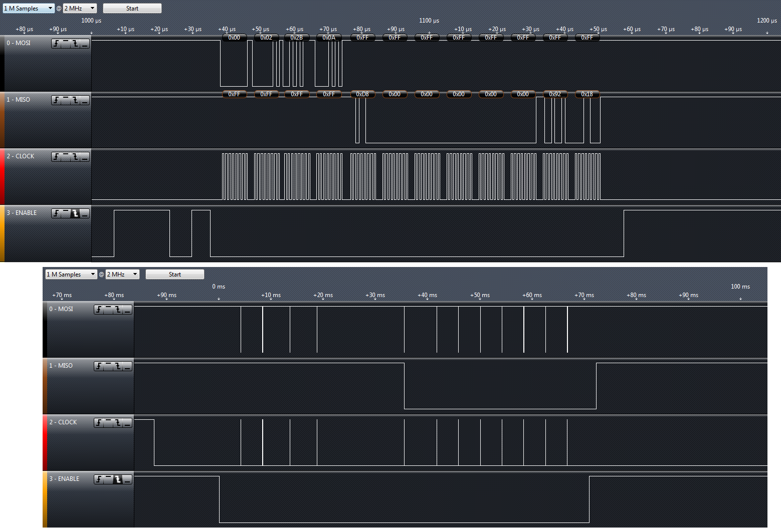
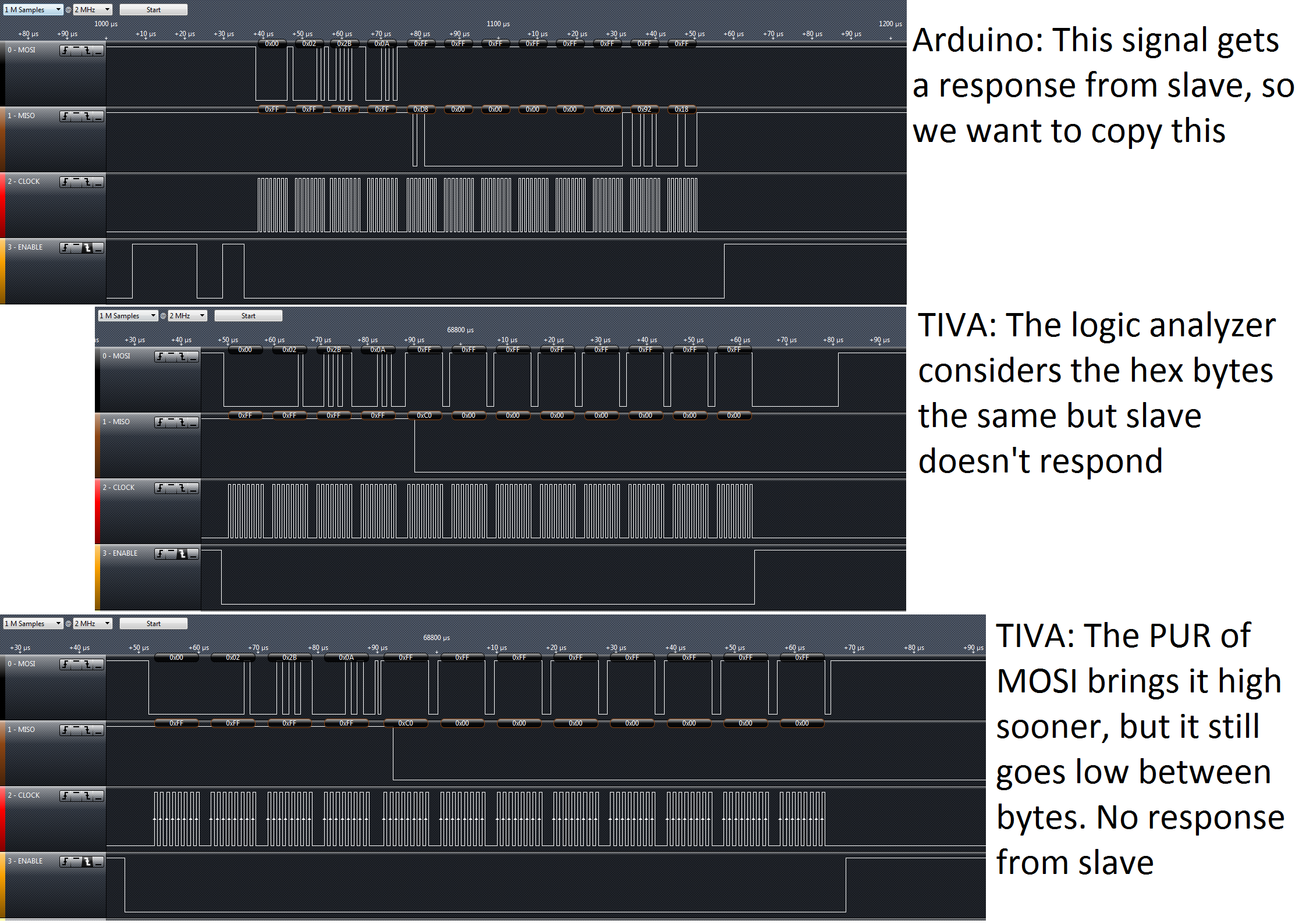
I'm sending 4 bytes and then receiving 8 bytes. The SSIfss is not used. I'm using a GPIO as CS.

I am able to use SSIDataPut properly and verify with Logic Analyzer.

However, SSIDataGet is not reliable. It receives 4 bytes and then hangs at ssi.c:

//
// Wait until there is data to be read.
//
while(!(HWREG(ui32Base + SSI_O_SR) & SSI_SR_RNE))
{
}

What determines this?

My code:

    //
    // Initialize the data to send.
    //
    pui32DataTx2[0] = 0x00;
    pui32DataTx2[1] = 0x02;
    pui32DataTx2[2] = 0x2B;
    pui32DataTx2[3] = 0x0A;

    //
    // Display indication that the SSI is transmitting data.
    //
    UARTprintf("\nSent2:\n  ");

    //CS low
    GPIOPinWrite(GPIO_PORTH_BASE, GPIO_PIN_0, 0);

    //
    // Send 4 bytes of data.
    //
    for(ui32Index = 0; ui32Index < 4; ui32Index++)
    {
        //
        // Display the data that SSI is transferring.
        //
        UARTprintf("'%i' ", pui32DataTx2[ui32Index]);
        //
        // Send the data using the "blocking" put function.  This function
        // will wait until there is room in the send FIFO before returning.
        // This allows you to assure that all the data you send makes it into
        // the send FIFO.
        //
        SSIDataPut(SSI0_BASE, pui32DataTx2[ui32Index]);
    }

    //
    // Wait until SSI0 is done transferring all the data in the transmit FIFO.
    //
    while(SSIBusy(SSI0_BASE))
    {
    }


    //
    // Display indication that the SSI is receiving data.
    //
    UARTprintf("\nReceived2:\n  ");


    //
    // Display the 8 bytes of data that were read from RX FIFO.
    //
    for(ui32Index = 0; ui32Index < 8; ui32Index++)
    {
        //
        // Receive the data using the "blocking" Get function. This function
        // will wait until there is data in the receive FIFO before returning.
        //
        SSIDataGet(SSI0_BASE, &pui32DataRx2[ui32Index]);

        //
        // Since we are using 8-bit data, mask off the MSB.
        //
        pui32DataRx2[ui32Index] &= 0x00FF;

        //
        // Display the data that SSI0 received.
        //
    	UARTprintf("'%i' ", pui32DataRx2[ui32Index]);
    	UARTprintf("\nCount:'%i'", ui32Index);
    }

    //
    // Wait until SSI0 is done transferring all the data in the transmit FIFO.
    //
    while(SSIBusy(SSI0_BASE))
    {
    }
    //CS high
    GPIOPinWrite(GPIO_PORTH_BASE, GPIO_PIN_0, GPIO_PIN_0);

Thanks,

Stephen

  • Hello Stephen

    I do not see the SSI Initialization code, so I will go with the assumption that the SSI has been configured correctly.

    The SSI in TM4C devices in legacy mode require that to receive a byte you need to put a byte

    If you want to send 4 and receive 8, then SSI requires that you put 8 more dummy transfers. and at the same time when sending the 4, flush the RXFIFO

    The SSI has a FIFO of 8 locations depth. When using the legacy mode, every time SSIDataPut is called, the RXFIFO is filled with one transfer. Thus with 4 SSIDataPut there are already 4 transfers in the RXFIFO. When it enters the loop to read the data it will read out 4 transfers and then wait.

    Regards

    Amit

  • Ok I made some changes and now I see the outputs on the logic analyzer and the code does not hang.

    Just to confirm the process:

    1) Empty the RXFIFO

        while(SSIDataGetNonBlocking(SSI0_BASE, &pui32DataRx2[0]))
        {
        }

    2) Send 4 Bytes and wait for SSI to finish transferring

        for(ui32Index = 0; ui32Index < 4; ui32Index++)
        {
            SSIDataPut(SSI0_BASE, pui32DataTx2[ui32Index]);
        }
    
        while(SSIBusy(SSI0_BASE))
        {
        }

    3) Empty the RXFIFO

        while(SSIDataGetNonBlocking(SSI0_BASE, &pui32DataRx2[0]))
        {
        }

    4) Send 8 dummy bytes while receive 8 bytes

        for(ui32Index = 0; ui32Index < 8; ui32Index++)
        {
        	//
        	// Put dummy bytes out to read bytes in
        	//
        	SSIDataPut(SSI0_BASE, 0);
            //
            // Receive the data using the "blocking" Get function. This function
            // will wait until there is data in the receive FIFO before returning.
            //
            SSIDataGet(SSI0_BASE, &pui32DataRx2[ui32Index]);
    
            //
            // Since we are using 8-bit data, mask off the MSB.
            //
            pui32DataRx2[ui32Index] &= 0x00FF;
    
            //
            // Display the data that SSI0 received.
            //
        	UARTprintf("'%i' ", pui32DataRx2[ui32Index]);
        }

    Is this correct?

  • Hello Stephen

    Yes, it is...

    Regards

    Amit

  • Hi Amit

    I do have one additional question related to all this.

    I used a logic analyzer to check the timing of the messages and it appears that the TIVA takes a very long time between bytes (5ms) compared to Arduino (2us).

    I'm running a very simple for loop in main... why does it take so long?

  • Hello Stephen,

    Can you please let me know what the System Clock and SSI Baud Clock are? Also in the diagram where do you see the time between bytes (you can mark it up in the snapshot).

    Also a publish of your full code would be rather useful

    Regards

    Amit

  • Hi Amit, thanks for the quick reply

    In the picture I sent you can see that the top image shows the 12 bytes being sent without much delay. In the bottom image has long delays between each byte sent. The time scale is shown at the top bar of each image.

    SSI clock is at 1MHz and System Clock is at 120MHz

    Here is the code:

    #include <stdbool.h>
    #include <stdint.h>
    
    #include "inc/hw_memmap.h"
    #include "inc/hw_ints.h"
    #include "inc/hw_nvic.h"
    #include "inc/hw_types.h"
    
    #include "driverlib/gpio.h"
    #include "driverlib/interrupt.h"
    #include "driverlib/pin_map.h"
    #include "driverlib/ssi.h"
    #include "driverlib/sysctl.h"
    #include "driverlib/systick.h"
    #include "driverlib/rom.h"
    #include "driverlib/rom_map.h"
    #include "driverlib/uart.h"
    
    #include "utils/uartstdio.h"
    
    #include "drivers/pinout.h"
    
    
    //*****************************************************************************
    //
    // System clock rate in Hz.
    //
    //*****************************************************************************
    uint32_t g_ui32SysClock;
    
    
    //*****************************************************************************
    //
    // Configure the UART and its pins.  This must be called before UARTprintf().
    //
    //*****************************************************************************
    void
    ConfigureUART(void)
    {
        //
        // Enable the GPIO Peripheral used by the UART.
        //
        SysCtlPeripheralEnable(SYSCTL_PERIPH_GPIOA);
    
        //
        // Enable UART0
        //
        SysCtlPeripheralEnable(SYSCTL_PERIPH_UART0);
    
        //
        // Configure GPIO Pins for UART mode.
        //
        GPIOPinConfigure(GPIO_PA0_U0RX);
        GPIOPinConfigure(GPIO_PA1_U0TX);
        GPIOPinTypeUART(GPIO_PORTA_BASE, GPIO_PIN_0 | GPIO_PIN_1);
    
        //
        // Initialize the UART for console I/O.
        //
        UARTStdioConfig(0, 9600, g_ui32SysClock);
    }
    
    
    //*****************************************************************************
    //
    // This function sets up SPI0 to be used as Master in freescale mode.
    //
    //*****************************************************************************
    void
    InitSPI0(void)
    {
        //
        // The SSI0 peripheral must be enabled for use.
        //
        SysCtlPeripheralEnable(SYSCTL_PERIPH_SSI0);
    
        //
        // For this example SSI0 is used with PortA[5:2].  The actual port and pins
        // used may be different on your part, consult the data sheet for more
        // information.  GPIO port A needs to be enabled so these pins can be used.
        // TODO: change this to whichever GPIO port you are using.
        //
        SysCtlPeripheralEnable(SYSCTL_PERIPH_GPIOA);
    
        //
        // Configure the pin muxing for SSI0 functions on port A2, A3, A4, and A5.
        // This step is not necessary if your part does not support pin muxing.
        // TODO: change this to select the port/pin you are using.
        //
        GPIOPinConfigure(GPIO_PA2_SSI0CLK);
        GPIOPinConfigure(GPIO_PA3_SSI0FSS);
        GPIOPinConfigure(GPIO_PA4_SSI0XDAT0);
        GPIOPinConfigure(GPIO_PA5_SSI0XDAT1);
    
        //
        // Configure the GPIO settings for the SSI pins.  This function also gives
        // control of these pins to the SSI hardware.  Consult the data sheet to
        // see which functions are allocated per pin.
        // The pins are assigned as follows:
        //      PA5 - SSI0Rx
        //      PA4 - SSI0Tx
        //      PA3 - SSI0Fss
        //      PA2 - SSI0CLK
        // TODO: change this to select the port/pin you are using.
        //
        GPIOPinTypeSSI(GPIO_PORTA_BASE, GPIO_PIN_5 | GPIO_PIN_4 | GPIO_PIN_3 | GPIO_PIN_2);
    
    
        //
        // Configure and enable the SSI port for SPI master mode.  Use SSI0,
        // system clock supply, idle clock level low and active low clock in
        // freescale SPI mode, master mode, 1MHz SSI frequency, and 8-bit data.
        // For SPI mode, you can set the polarity of the SSI clock when the SSI
        // unit is idle.  You can also configure what clock edge you want to
        // capture data on.  Please reference the datasheet for more information on
        // the different SPI modes.
        //
        SSIConfigSetExpClk(SSI0_BASE, g_ui32SysClock, SSI_FRF_MOTO_MODE_0,
                           SSI_MODE_MASTER, 1000000, 8);
    
        //
        // Enable the SSI0 module.
        //
        SSIEnable(SSI0_BASE);
    }
    
    //*****************************************************************************
    //
    // Configure GPIO pins.  This replaces the SSI0Fss with another pin.
    //
    //*****************************************************************************
    void
    InitGPIO(void)
    {
    	SysCtlPeripheralEnable(SYSCTL_PERIPH_GPIOH);
    	GPIOPinTypeGPIOOutput(GPIO_PORTH_BASE, GPIO_PIN_0);
    	GPIOPinWrite(GPIO_PORTH_BASE, GPIO_PIN_0, GPIO_PIN_0);
    
    }
    
    //*****************************************************************************
    //
    // Configure SSI0 in master Freescale (SPI) mode.  This example will send out
    // 3 bytes of data, then wait for 3 bytes of data to come in.  This will all be
    // done using the polling method.
    //
    //*****************************************************************************
    int
    main(void)
    {
        uint32_t pui32DataTx2[4];
        uint32_t pui32DataRx2[8];
        uint32_t ui32Index;
    
    
        //
        // Set the clocking to run directly from the external crystal/oscillator.
        // TODO: The SYSCTL_XTAL_ value must be changed to match the value of the
        // crystal on your board.
        //
        g_ui32SysClock = SysCtlClockFreqSet((SYSCTL_XTAL_25MHZ |
                    SYSCTL_OSC_MAIN | SYSCTL_USE_PLL |
                    SYSCTL_CFG_VCO_480), 120000000);
    
        //
        // Set up the serial console to use for displaying messages.  This is
        // just for this example program and is not needed for SSI operation.
        //
        ConfigureUART();
    
        //
        // Initialize and enable CS
        //
        InitGPIO();
    
        //
        // Display the setup on the console.
        //
        UARTprintf("\n\nSSI ->\n");
        UARTprintf("  Mode: SPI\n");
        UARTprintf("  Data: 8-bit\n\n");
    
        //
        // Init SPI0 as master.
        //
        InitSPI0();
    
    
        //
        // Read any residual data from the SSI port.  This makes sure the receive
        // FIFOs are empty, so we don't read any unwanted junk.  This is done here
        // because the SPI SSI mode is full-duplex, which allows you to send and
        // receive at the same time.  The SSIDataGetNonBlocking function returns
        // "true" when data was returned, and "false" when no data was returned.
        // The "non-blocking" function checks if there is any data in the receive
        // FIFO and does not "hang" if there isn't.
        //
        while(SSIDataGetNonBlocking(SSI0_BASE, &pui32DataRx2[0]))
        {
        }
    
        //
        // Initialize the data to send.
        //
        pui32DataTx2[0] = 0x00;
        pui32DataTx2[1] = 0x02;
        pui32DataTx2[2] = 0x2B;
        pui32DataTx2[3] = 0x0A;
    
        //
        // Display indication that the SSI is transmitting data.
        //
        UARTprintf("\nSent2:\n  ");
    
        //CS low
        GPIOPinWrite(GPIO_PORTH_BASE, GPIO_PIN_0, 0);
    
        //
        // Send 4 bytes of data.
        //
        for(ui32Index = 0; ui32Index < 4; ui32Index++)
        {
            //
            // Display the data that SSI is transferring.
            //
            UARTprintf("'%i' ", pui32DataTx2[ui32Index]);
            //
            // Send the data using the "blocking" put function.  This function
            // will wait until there is room in the send FIFO before returning.
            // This allows you to assure that all the data you send makes it into
            // the send FIFO.
            //
            SSIDataPut(SSI0_BASE, pui32DataTx2[ui32Index]);
        }
    
        //
        // Wait until SSI0 is done transferring all the data in the transmit FIFO.
        //
        while(SSIBusy(SSI0_BASE))
        {
        }
    
    
        //
        // Read any residual data from the SSI port.  This makes sure the receive
        // FIFOs are empty, so we don't read any unwanted junk.  This is done here
        // because the SPI SSI mode is full-duplex, which allows you to send and
        // receive at the same time.  The SSIDataGetNonBlocking function returns
        // "true" when data was returned, and "false" when no data was returned.
        // The "non-blocking" function checks if there is any data in the receive
        // FIFO and does not "hang" if there isn't.
        //
        while(SSIDataGetNonBlocking(SSI0_BASE, &pui32DataRx2[0]))
        {
        }
    
    
        //
        // Display indication that the SSI is receiving data.
        //
        UARTprintf("\nReceived2:\n  ");
    
    
        //
        // Display the 8 bytes of data that were read from RX FIFO.
        //
        for(ui32Index = 0; ui32Index < 8; ui32Index++)
        {
        	//
        	// Put dummy bytes out to read bytes in
        	//
        	SSIDataPut(SSI0_BASE, 0xFF);
            //
            // Receive the data using the "blocking" Get function. This function
            // will wait until there is data in the receive FIFO before returning.
            //
            SSIDataGet(SSI0_BASE, &pui32DataRx2[ui32Index]);
    
            //
            // Since we are using 8-bit data, mask off the MSB.
            //
            pui32DataRx2[ui32Index] &= 0x00FF;
    
            //
            // Display the data that SSI0 received.
            //
        	UARTprintf("'%i' ", pui32DataRx2[ui32Index]);
        }
    
        //
        // Wait until SSI0 is done transferring all the data in the transmit FIFO.
        //
        while(SSIBusy(SSI0_BASE))
        {
        }
        //CS high
        GPIOPinWrite(GPIO_PORTH_BASE, GPIO_PIN_0, GPIO_PIN_0);
    
        //
        // Return no errors
        //
        return(0);
    }
    

  • Hello Stephen

    The long delay is because of the slower UARTprintf. My suggestion would be to comment the same out, increase the baud rate to 60 (SSI supports upto 60MHz on SSI Master side) instead of 1 if the external slave device supports, or else to the maximum the slave device can support.

    Regards

    Amit

  • Wow very good catch! Much better now

    For some reason, slave still not replying to me.

    Is there a way to set MOSI high like in the top picture? I'm trying to make them identical

  • Hello Stephen,

    Can you enable the Pull Up for the SSI Pad which has MOSI

    Regards

    Amit

  • Where do I do that? Not sure what you mean..

  • Hello Stephen

    As part of InitGPIO. You can add the following code (first line will disable if any on PA3 pad which has FSS and second line would enable the actual pull up)

    HWREG(GPIO_PORTA_BASE+GPIO_0_PDR) &= 0xF7;

    HWREG(GPIO_PORTA_BASE+GPIO_0_PUR) |= 0x8;

    after

    GPIOPinTypeSSI(GPIO_PORTA_BASE, GPIO_PIN_5 | GPIO_PIN_4 | GPIO_PIN_3 | GPIO_PIN_2);

    Regards

    Amit

  • "../spi_master.c", line 217: error #20: identifier "GPIO_0_PDR" is undefined
    "../spi_master.c", line 218: error #20: identifier "GPIO_0_PUR" is undefined

    Where can I find this info?

  • Hello Stephen

    You would need to include hw_gpio.h as follows

    #include "inc/hw_gpio.h"

    If there is an error still just have a look at the file mentioned above in the TivaWare for the exact name of the register macro as defined in the file

    Regards

    Amit

  • Hi Amit,

    Code compiles and runs just find but the results are the same.

    It seems SSI MOSI always drops low between passing information.

    What else can we do to make it stay high between bytes?

    Thanks,

    Stephen

  • Hello Stephen,

    I am a bit surprised. The Pull up should be effective if the pad is tri-stated during idle time. The other alternative would be turn the SSI FSS to a GPIO by calling GPIOPinWrite and GPIOPinTypeGPIOOutput after the TX function of the code is over. And after receive it must be re-configured as SSI FSS.

    Let me run the code as I am sure if the pin is not driven the pull controls should work.

    Regards

    Amit

  • Hi,

    For Freescale mode 0, the SPI should rise the FSS pin (either automatic, either GPIO) after each sent word (byte in your case), since only at rise up the data is transferred to the slave registers. 

    Stephen trys to do back to back transmission and rise up after 4/8 bytes, shoud modify the software and rise up the pin after each transmitted byte and then wait for the minimum 50 ns until the pin can be used again for a new byte transmission.

    Petrei

  • Hi All,

    I'm not quite sure what Fss has to do with anything since I am not using that pin at all...

    I'm using a GPIO as CS(Enable) to the slave.

    I've attached the picture to show that PUR does do something to the MOSI (it pulls it up earlier at the end, but not between bytes)

    Maybe you guys will think of something I missed

    Thanks,

    Stephen

  • Hello Stephen,

    Which slave device is this? May be we need to go through the slave device data sheet to see if this behavior is acceptable to the slave or not in the first place.

    Regards

    Amit

  • 1072.LTC6804-2_Programming_Guide_v20130814.pdf

    I've attached the programming guide for the slave.

    Page 3 refers to the SPI behavior.

    And this Excel file explains the timing intervals

    2308.LTC6804-1-2_SPI_MasterTiming_v030.xls

    I'm currently working on modifying the CSB(Enable) timing to see if it changes anything

  • Hello Stephen

    There is nothing in the document to suggest that the MOSI pin has to be high all along. However still to check if it is something that the LTC device expects, I have attached a code that will make MOSI pin high by configuring it as GPIO

    int
    main(void)
    {
        uint32_t pui32DataTx2[4];
        uint32_t pui32DataRx2[8];
        uint32_t ui32Index;
        //
        // Set the clocking to run directly from the external crystal/oscillator.
        // TODO: The SYSCTL_XTAL_ value must be changed to match the value of the
        // crystal on your board.
        //
        g_ui32SysClock = SysCtlClockFreqSet((SYSCTL_XTAL_25MHZ |
                    SYSCTL_OSC_MAIN | SYSCTL_USE_PLL |
                    SYSCTL_CFG_VCO_480), 120000000);
        //
        // Set up the serial console to use for displaying messages.  This is
        // just for this example program and is not needed for SSI operation.
        //
        ConfigureUART();
        //
        // Initialize and enable CS
        //
        InitGPIO();
        //
        // Display the setup on the console.
        //
        UARTprintf("\n\nSSI ->\n");
        UARTprintf("  Mode: SPI\n");
        UARTprintf("  Data: 8-bit\n\n");
        //
        // Init SPI0 as master.
        //
        InitSPI0();
        //
        // Read any residual data from the SSI port.  This makes sure the receive
        // FIFOs are empty, so we don't read any unwanted junk.  This is done here
        // because the SPI SSI mode is full-duplex, which allows you to send and
        // receive at the same time.  The SSIDataGetNonBlocking function returns
        // "true" when data was returned, and "false" when no data was returned.
        // The "non-blocking" function checks if there is any data in the receive
        // FIFO and does not "hang" if there isn't.
        //
        while(SSIDataGetNonBlocking(SSI0_BASE, &pui32DataRx2[0]))
        {
        }
        //
        // Initialize the data to send.
        //
        pui32DataTx2[0] = 0x00;
        pui32DataTx2[1] = 0x02;
        pui32DataTx2[2] = 0x2B;
        pui32DataTx2[3] = 0x0A;
        //
        // Display indication that the SSI is transmitting data.
        //
        GPIOPinWrite(GPIO_PORTH_BASE, GPIO_PIN_0, 0x0);
    	
        //
        // Send 4 bytes of data.
        //
        for(ui32Index = 0; ui32Index < 4; ui32Index++)
        {
            //
            // Send the data using the "blocking" put function.  This function
            // will wait until there is room in the send FIFO before returning.
            // This allows you to assure that all the data you send makes it into
            // the send FIFO.
            //
            SSIDataPut(SSI0_BASE, pui32DataTx2[ui32Index]);
        }
        //
        // Wait until SSI0 is done transferring all the data in the transmit FIFO.
        //
        while(SSIBusy(SSI0_BASE))
        {
        }
    
        GPIOPinWrite(GPIO_PORTA_BASE, GPIO_PIN_4, GPIO_PIN_4);
    	GPIOPinTypeGPIOOutput(GPIO_PORTA_BASE, GPIO_PIN_4);
        //
        // Read any residual data from the SSI port.  This makes sure the receive
        // FIFOs are empty, so we don't read any unwanted junk.  This is done here
        // because the SPI SSI mode is full-duplex, which allows you to send and
        // receive at the same time.  The SSIDataGetNonBlocking function returns
        // "true" when data was returned, and "false" when no data was returned.
        // The "non-blocking" function checks if there is any data in the receive
        // FIFO and does not "hang" if there isn't.
        //
        while(SSIDataGetNonBlocking(SSI0_BASE, &pui32DataRx2[0]))
        {
        }
    
        //
        // Display the 8 bytes of data that were read from RX FIFO.
        //
        for(ui32Index = 0; ui32Index < 8; ui32Index++)
        {
            //
            // Put dummy bytes out to read bytes in
            //
            SSIDataPut(SSI0_BASE, 0xFF);
            //
            // Receive the data using the "blocking" Get function. This function
            // will wait until there is data in the receive FIFO before returning.
            //
            SSIDataGet(SSI0_BASE, &pui32DataRx2[ui32Index]);
            //
            // Since we are using 8-bit data, mask off the MSB.
            //
            pui32DataRx2[ui32Index] &= 0x00FF;
        }
        //
        // Wait until SSI0 is done transferring all the data in the transmit FIFO.
        //
        while(SSIBusy(SSI0_BASE))
        {
        }
        //CS high
        GPIOPinWrite(GPIO_PORTH_BASE, GPIO_PIN_0, GPIO_PIN_0);
        //
        // Return no errors
        //
        return(0);
    }

    Regards

    Amit

  • Hi,

    The data sheet of the chip is somewhat contradictory - while at the beginning specify for SPI either mode 0 or mode 3, for the master chip is mandatory the mode 3, as expressely specified on page 31 and repeated on page 35.

    Also, on page 31, there is a mention stating the MOSI/MISO pins are open drain, so some pull-ups are needed.

    The programming guide states the possibility to have unresponsive devices due to wrong clock phases at 1MHz, suggesting to use 100KHz - maybe at the least at the beginning, until all is set up correctly.

    Petrei

  • Hi Amit,

    I've tried using GPIO to pull MOSI up. It doesn't do it as long as its being accessed by ssi. I believe it is a hardcoded part of SSI; maybe we can't change it? Linear Technology hasn't been very responsive in offering advice. I'm glad TI has better technical support.

    Hi Petrei

    I've tried all the configurations recommended by datasheet (Mode0, Mode3, SSI clock to 100kHz etc). I haven't added external pull up resistors because this board works with Arduino out of the box.

    Here is what TIVA looks like in Mode3 (notice it doesn't pull low between bytes but the clock is very close together for some reason. For the record, the Arduino SPI is Mode0 at 1MHz.

    Now the million dollar question guys..

    Is there any hardware differences that make a TIVA and Arduino so different? I am hooking up the exact same pins on TIVA as Arduino (VCC, GND, MISO, MOSI, SCK, CS) nothing else. I'm reading the exact same MOSI message from the Logic Analyzer(0x00 0x02 0x2B 0x0A 0xFF 0xFF 0xFF 0xFF 0xFF 0xFF 0xFF 0xFF). Why is the MISO returning valid data to Arduino but now TIVA?

  • Hello Stephen

    What is the Vreg supply of LTC connected to. As per the data sheet it is supposed to 5V. However TM4C will work only maximum up to 3.63V (+10% of 3.3V)

    Regards

    Amit

  • Hi Amit,

    I measured 3.2V from VREG to LTC6804V- (GND).

    What is the applicable pull up resistor value on the TIVA MISO? I know there are 4 current drains or something like that.

    Could this be my solution?

    Thanks,

    Stephen

  • Hello Stephen

    The LTC device is mentioned to be a 5V device. I don't think it would be operational. On the Arduino board what is the Vreg measured as?

    Regards

    Amit

  • Hi Amit,

    I measure 5V from the Arduino...

    HOWEVER! According to the Linear datasheet, the Vreg for digital is 2.7 to 3.6

    http://cds.linear.com/docs/en/datasheet/680412fb.pdf

    Very odd eh

    Stephen

  • VregD is the digital supply internal to the device and there is no external access. 3.3V logic levels to the 6804 is okay because the 6804 DS pg 7 states logic high = 2.3V min and logic low = 0.8V max.  


    The MISO pullup resistor should really tied between the uC’s VDD and SDI pins, which makes sense that MISO line should be the same logic level as the uC. So instead of adding a 1k Rpullup between 5Vreg and MISO on DC1894 R63, temporarily wire up with clip-to-clips a 1k between TM4C’s MISO pin and VDD pin. The readback is correct.

    The problem is now solved.

    Thanks everyone!

  • Hello Stephen

    Great and congrats...

    Regards

    Amit

  • hello stephen keng 

    i am working on LTC6804 from last few month , i was trying to port linux application connected LTC6804 with Beagle

    Xm but  some issues occur.  this is the git application source i am using  ("https://github.com/martin-c/beagle-bms" ) .

    where my beagle xm is connected with LTC6802 ("http://cds.linear.com/docs/en/demo-board-manual/dc1941bf.pdf")

    which is connected to LTC6804 DC1942B isoSPI bus ("http://cds.linear.com/docs/en/demo-board-manual/dc1942bf.pdf")

    but i didnt get the spi driver for the board . board file  

    /*
     * Code for AM335X EVM.
     *
     * Copyright (C) 2011 Texas Instruments, Inc. - http://www.ti.com/
     *
     * This program is free software; you can redistribute it and/or
     * modify it under the terms of the GNU General Public License as
     * published by the Free Software Foundation version 2.
     *
     * This program is distributed "as is" WITHOUT ANY WARRANTY of any
     * kind, whether express or implied; without even the implied warranty
     * of MERCHANTABILITY or FITNESS FOR A PARTICULAR PURPOSE.  See the
     * GNU General Public License for more details.
     */
    #include <linux/kernel.h>
    #include <linux/init.h>
    #include <linux/i2c.h>
    #include <linux/module.h>
    #include <linux/i2c/at24.h>
    #include <linux/phy.h>
    #include <linux/gpio.h>
    #include <linux/spi/spi.h>
    #include <linux/spi/flash.h>
    #include <linux/gpio_keys.h>
    #include <linux/input.h>
    #include <linux/input/matrix_keypad.h>
    #include <linux/mtd/mtd.h>
    #include <linux/mtd/nand.h>
    #include <linux/mtd/partitions.h>
    #include <linux/platform_device.h>
    #include <linux/clk.h>
    #include <linux/err.h>
    #include <linux/export.h>
    #include <linux/wl12xx.h>
    #include <linux/ethtool.h>
    #include <linux/mfd/tps65910.h>
    #include <linux/mfd/tps65217.h>
    #include <linux/pwm_backlight.h>
    #include <linux/input/ti_tscadc.h>
    #include <linux/reboot.h>
    #include <linux/pwm/pwm.h>
    #include <linux/opp.h>
    
    /* LCD controller is similar to DA850 */
    #include <video/da8xx-fb.h>
    
    #include <mach/hardware.h>
    #include <mach/board-am335xevm.h>
    
    #include <asm/mach-types.h>
    #include <asm/mach/arch.h>
    #include <asm/mach/map.h>
    #include <asm/hardware/asp.h>
    
    #include <plat/omap_device.h>
    #include <plat/irqs.h>
    #include <plat/board.h>
    #include <plat/common.h>
    #include <plat/lcdc.h>
    #include <plat/usb.h>
    #include <plat/mmc.h>
    #include <plat/emif.h>
    #include <plat/nand.h>
    
    #include "board-flash.h"
    #include "cpuidle33xx.h"
    #include "mux.h"
    #include "devices.h"
    #include "hsmmc.h"
    
    /* Convert GPIO signal to GPIO pin number */
    #define GPIO_TO_PIN(bank, gpio) (32 * (bank) + (gpio))
    
    static const struct display_panel disp_panel = {
            WVGA,
            16,
            16,
            COLOR_ACTIVE,
    };
    
    static struct lcd_ctrl_config lcd_cfg = {
            &disp_panel,
            .ac_bias                = 255,
            .ac_bias_intrpt         = 0,
            .dma_burst_sz           = 16,
            .bpp                    = 16,
            .fdd                    = 255,
            .tft_alt_mode           = 0,
            .stn_565_mode           = 0,
            .mono_8bit_mode         = 0,
            .invert_line_clock      = 1,
            .invert_frm_clock       = 1,
            .sync_edge              = 0,
            .sync_ctrl              = 1,
            .raster_order           = 0,
    };
    
    #ifdef CONFIG_CALIXTO_VGA_SUPPORT
    struct da8xx_lcdc_platform_data calixtovga_pdata = {
            .manu_name              = "VGA",
            .controller_data        = &lcd_cfg,
            .type                   = "CalixtoVGA",
    };
    #endif
    
    #ifdef CONFIG_CALIXTO_VGA_1280X720
    struct da8xx_lcdc_platform_data calixtovga_pdata = {
            .manu_name              = "VGA",
            .controller_data        = &lcd_cfg,
            .type                   = "1280@720res",
    };
    #endif
    
    struct da8xx_lcdc_platform_data calixtolcd4_pdata = {
            .manu_name              = "cslcd4",
            .controller_data        = &lcd_cfg,
            .type                   = "CALIXTOLCD4",
    };
    
    struct da8xx_lcdc_platform_data calixtolcd7old_pdata = {
            .manu_name              = "cslcd7",
            .controller_data        = &lcd_cfg,
            .type                   = "LCD7OLD",
    };
    
    struct da8xx_lcdc_platform_data calixtolcd7new_pdata = {
            .manu_name              = "cslcd7",
            .controller_data        = &lcd_cfg,
            .type                   = "LCD7NEW",
    };
    
    struct da8xx_lcdc_platform_data calixtolcd35_pdata = {
            .manu_name              = "cslcd35",
            .controller_data        = &lcd_cfg,
            .type                   = "Tianma_35",
    };
    
    #include "common.h"
    
    /* TSc controller */
    static struct tsc_data am335x_touchscreen_data  = {
    	.wires  = 4,
    	.x_plate_resistance = 200,
    };
    
    static u8 am335x_calixto_iis_serializer_direction[] = {
           TX_MODE,        RX_MODE,        INACTIVE_MODE,  INACTIVE_MODE,
           INACTIVE_MODE,  INACTIVE_MODE,  INACTIVE_MODE,  INACTIVE_MODE,
           INACTIVE_MODE,  INACTIVE_MODE,  INACTIVE_MODE,  INACTIVE_MODE,
           INACTIVE_MODE,  INACTIVE_MODE,  INACTIVE_MODE,  INACTIVE_MODE,
    };
    
    static struct snd_platform_data am335x_evm_snd_data0 = {
            .tx_dma_offset  = 0x46000000,   /* McASP0 */
            .rx_dma_offset  = 0x46000000,
            .op_mode        = DAVINCI_MCASP_IIS_MODE,
            .num_serializer = ARRAY_SIZE(am335x_calixto_iis_serializer_direction),
            .tdm_slots      = 2,
            .serial_dir     = am335x_calixto_iis_serializer_direction,
            .asp_chan_q     = EVENTQ_2,
            .version        = MCASP_VERSION_3,
            .txnumevt       = 1,
            .rxnumevt       = 1,
    };
    
    static struct omap2_hsmmc_info am335x_mmc[] __initdata = {
    	{
    		.mmc            = 1,
    		.caps           = MMC_CAP_4_BIT_DATA,
    		.gpio_cd        = GPIO_TO_PIN(3, 14),
    		.gpio_wp        = GPIO_TO_PIN(0, 7),
    		.ocr_mask       = MMC_VDD_32_33 | MMC_VDD_33_34, /* 3V3 */
    	},
    	{
    		.mmc            = 0,	/* will be set at runtime */
    	},
    	{
    		.mmc            = 0,	/* will be set at runtime */
    	},
    	{}      /* Terminator */
    };
    
    
    #ifdef CONFIG_OMAP_MUX
    static struct omap_board_mux board_mux[] __initdata = {
    	/*
    	 * Setting SYSBOOT[5] should set xdma_event_intr0 pin to mode 3 thereby
    	 * allowing clkout1 to be available on xdma_event_intr0.
    	 * However, on some boards (like EVM-SK), SYSBOOT[5] isn't properly
    	 * latched.
    	 * To be extra cautious, setup the pin-mux manually.
    	 * If any modules/usecase requries it in different mode, then subsequent
    	 * module init call will change the mux accordingly.
    	 */
    	AM33XX_MUX(XDMA_EVENT_INTR0, OMAP_MUX_MODE3 | AM33XX_PIN_OUTPUT),
    	AM33XX_MUX(I2C0_SDA, OMAP_MUX_MODE0 | AM33XX_SLEWCTRL_SLOW |
    			AM33XX_INPUT_EN | AM33XX_PIN_OUTPUT),
    	AM33XX_MUX(I2C0_SCL, OMAP_MUX_MODE0 | AM33XX_SLEWCTRL_SLOW |
    			AM33XX_INPUT_EN | AM33XX_PIN_OUTPUT),
    	{ .reg_offset = OMAP_MUX_TERMINATOR },
    };
    #else
    #define	board_mux	NULL
    #endif
    
    /* module pin mux structure */
    struct pinmux_config {
      const char *string_name; /* signal name format */
      int val; /* Options for the mux register value */
    };
    
    struct evm_dev_cfg {
      void (*device_init)(int evm_id, int profile);
    
    #define DEV_ON_BASEBOARD  0
      u32 device_on;
      u32 profile;
    };
    
    static bool daughter_brd_detected;
    static int am33xx_evmid = -EINVAL;
    
    void am335x_evm_set_id(unsigned int evmid)
    {
       am33xx_evmid = evmid;
    	return;
    }
    
    int am335x_evm_get_id(void)
    {
       return am33xx_evmid;
    }
    EXPORT_SYMBOL(am335x_evm_get_id);
    
    /* Module pin mux for LCDC */
    static struct pinmux_config lcdc_pin_mux[] = {
    	{"lcd_data0.lcd_data0",		OMAP_MUX_MODE0 | AM33XX_PIN_OUTPUT
    						       | AM33XX_PULL_DISA},
    	{"lcd_data1.lcd_data1",		OMAP_MUX_MODE0 | AM33XX_PIN_OUTPUT
    						       | AM33XX_PULL_DISA},
    	{"lcd_data2.lcd_data2",		OMAP_MUX_MODE0 | AM33XX_PIN_OUTPUT
    						       | AM33XX_PULL_DISA},
    	{"lcd_data3.lcd_data3",		OMAP_MUX_MODE0 | AM33XX_PIN_OUTPUT
    						       | AM33XX_PULL_DISA},
    	{"lcd_data4.lcd_data4",		OMAP_MUX_MODE0 | AM33XX_PIN_OUTPUT
    						       | AM33XX_PULL_DISA},
    	{"lcd_data5.lcd_data5",		OMAP_MUX_MODE0 | AM33XX_PIN_OUTPUT
    						       | AM33XX_PULL_DISA},
    	{"lcd_data6.lcd_data6",		OMAP_MUX_MODE0 | AM33XX_PIN_OUTPUT
    						       | AM33XX_PULL_DISA},
    	{"lcd_data7.lcd_data7",		OMAP_MUX_MODE0 | AM33XX_PIN_OUTPUT
    						       | AM33XX_PULL_DISA},
    	{"lcd_data8.lcd_data8",		OMAP_MUX_MODE0 | AM33XX_PIN_OUTPUT
    						       | AM33XX_PULL_DISA},
    	{"lcd_data9.lcd_data9",		OMAP_MUX_MODE0 | AM33XX_PIN_OUTPUT
    						       | AM33XX_PULL_DISA},
    	{"lcd_data10.lcd_data10",	OMAP_MUX_MODE0 | AM33XX_PIN_OUTPUT
    						       | AM33XX_PULL_DISA},
    	{"lcd_data11.lcd_data11",	OMAP_MUX_MODE0 | AM33XX_PIN_OUTPUT
    						       | AM33XX_PULL_DISA},
    	{"lcd_data12.lcd_data12",	OMAP_MUX_MODE0 | AM33XX_PIN_OUTPUT
    						       | AM33XX_PULL_DISA},
    	{"lcd_data13.lcd_data13",	OMAP_MUX_MODE0 | AM33XX_PIN_OUTPUT
    						       | AM33XX_PULL_DISA},
    	{"lcd_data14.lcd_data14",	OMAP_MUX_MODE0 | AM33XX_PIN_OUTPUT
    						       | AM33XX_PULL_DISA},
    	{"lcd_data15.lcd_data15",	OMAP_MUX_MODE0 | AM33XX_PIN_OUTPUT
    						       | AM33XX_PULL_DISA},
    	{"lcd_vsync.lcd_vsync",		OMAP_MUX_MODE0 | AM33XX_PIN_OUTPUT},
    	{"lcd_hsync.lcd_hsync",		OMAP_MUX_MODE0 | AM33XX_PIN_OUTPUT},
    	{"lcd_pclk.lcd_pclk",		OMAP_MUX_MODE0 | AM33XX_PIN_OUTPUT},
    	{"lcd_ac_bias_en.lcd_ac_bias_en", OMAP_MUX_MODE0 | AM33XX_PIN_OUTPUT},
    	{NULL, 0},
    };
    
    /* Touch Screen Controller */
    static struct pinmux_config tsc_pin_mux[] = {
    	{"ain0.ain0",           OMAP_MUX_MODE0 | AM33XX_INPUT_EN},
    	{"ain1.ain1",           OMAP_MUX_MODE0 | AM33XX_INPUT_EN},
    	{"ain2.ain2",           OMAP_MUX_MODE0 | AM33XX_INPUT_EN},
    	{"ain3.ain3",           OMAP_MUX_MODE0 | AM33XX_INPUT_EN},
    	{"ain4.ain4",           OMAP_MUX_MODE0 | AM33XX_INPUT_EN},
    	{"vrefp.vrefp",         OMAP_MUX_MODE0 | AM33XX_INPUT_EN},
    	{"vrefn.vrefn",         OMAP_MUX_MODE0 | AM33XX_INPUT_EN},
    	{NULL, 0},
    };
    
    /* Pin mux for nand flash module */
    static struct pinmux_config nand_pin_mux[] = {
    	{"gpmc_ad0.gpmc_ad0",	  OMAP_MUX_MODE0 | AM33XX_PIN_INPUT_PULLUP},
    	{"gpmc_ad1.gpmc_ad1",	  OMAP_MUX_MODE0 | AM33XX_PIN_INPUT_PULLUP},
    	{"gpmc_ad2.gpmc_ad2",	  OMAP_MUX_MODE0 | AM33XX_PIN_INPUT_PULLUP},
    	{"gpmc_ad3.gpmc_ad3",	  OMAP_MUX_MODE0 | AM33XX_PIN_INPUT_PULLUP},
    	{"gpmc_ad4.gpmc_ad4",	  OMAP_MUX_MODE0 | AM33XX_PIN_INPUT_PULLUP},
    	{"gpmc_ad5.gpmc_ad5",	  OMAP_MUX_MODE0 | AM33XX_PIN_INPUT_PULLUP},
    	{"gpmc_ad6.gpmc_ad6",	  OMAP_MUX_MODE0 | AM33XX_PIN_INPUT_PULLUP},
    	{"gpmc_ad7.gpmc_ad7",	  OMAP_MUX_MODE0 | AM33XX_PIN_INPUT_PULLUP},
    	{"gpmc_wait0.gpmc_wait0", OMAP_MUX_MODE0 | AM33XX_PIN_INPUT_PULLUP},
    	{"gpmc_wpn.gpmc_wpn",	  OMAP_MUX_MODE7 | AM33XX_PIN_INPUT_PULLUP},
    	{"gpmc_csn0.gpmc_csn0",	  OMAP_MUX_MODE0 | AM33XX_PULL_DISA},
    	{"gpmc_advn_ale.gpmc_advn_ale",  OMAP_MUX_MODE0 | AM33XX_PULL_DISA},
    	{"gpmc_oen_ren.gpmc_oen_ren",	 OMAP_MUX_MODE0 | AM33XX_PULL_DISA},
    	{"gpmc_wen.gpmc_wen",     OMAP_MUX_MODE0 | AM33XX_PULL_DISA},
    	{"gpmc_ben0_cle.gpmc_ben0_cle",	 OMAP_MUX_MODE0 | AM33XX_PULL_DISA},
    	{NULL, 0},
    };
    
    /* Module pin mux for SPI fash */
    /* module pin mux for LTC6804-2 "aartech"*/
    static struct pinmux_config spi0_pin_mux[] = {
    /*
    	{"spi0_sclk.spi0_sclk", OMAP_MUX_MODE0 | AM33XX_PULL_ENBL
    							| AM33XX_INPUT_EN},
    	{"spi0_d0.spi0_d0", OMAP_MUX_MODE0 | AM33XX_PULL_ENBL | AM33XX_PULL_UP
    							| AM33XX_INPUT_EN},
    	{"spi0_d1.spi0_d1", OMAP_MUX_MODE0 | AM33XX_PULL_ENBL
    							| AM33XX_INPUT_EN},
    	{"spi0_cs0.spi0_cs0", OMAP_MUX_MODE0 | AM33XX_PULL_ENBL | AM33XX_PULL_UP
    							| AM33XX_INPUT_EN},
    	{"spi0_cs1.spi0_cs1", OMAP_MUX_MODE0 | AM33XX_PULL_ENBL | AM33XX_PULL_UP
                                                            | AM33XX_INPUT_EN},
    	{NULL, 0},*/
           {"spi0_sclk.spi0_sclk", OMAP_MUX_MODE0 | AM33XX_PULL_ENBL
    							| AM33XX_INPUT_EN},
    	{"spi0_d0.spi0_d0", OMAP_MUX_MODE0 | AM33XX_PULL_ENBL | AM33XX_PULL_UP
    							| AM33XX_INPUT_EN},
    	{"spi0_d1.spi0_d1", OMAP_MUX_MODE0 | AM33XX_PULL_ENBL
    							| AM33XX_PIN_OUTPUT},
    	{"spi0_cs0.spi0_cs0", OMAP_MUX_MODE0 | AM33XX_PULL_ENBL | AM33XX_PULL_UP
    							| AM33XX_INPUT_EN},
    	{"spi0_cs1.spi0_cs1", OMAP_MUX_MODE0 | AM33XX_PULL_ENBL | AM33XX_PULL_UP
                                                            | AM33XX_INPUT_EN},
    	{NULL, 0}
    
    };
    
    /* Module pin mux for mii2 */
    static struct pinmux_config mii2_pin_mux[] = {
    	{"gpmc_wpn.mii2_rxerr", OMAP_MUX_MODE1 | AM33XX_PIN_INPUT_PULLDOWN},
    	{"gpmc_a0.mii2_txen", OMAP_MUX_MODE1 | AM33XX_PIN_OUTPUT},
    	{"gpmc_a1.mii2_rxdv", OMAP_MUX_MODE1 | AM33XX_PIN_INPUT_PULLDOWN},
    	{"gpmc_a2.mii2_txd3", OMAP_MUX_MODE1 | AM33XX_PIN_OUTPUT},
    	{"gpmc_a3.mii2_txd2", OMAP_MUX_MODE1 | AM33XX_PIN_OUTPUT},
    	{"gpmc_a4.mii2_txd1", OMAP_MUX_MODE1 | AM33XX_PIN_OUTPUT},
    	{"gpmc_a5.mii2_txd0", OMAP_MUX_MODE1 | AM33XX_PIN_OUTPUT},
    	{"gpmc_a6.mii2_txclk", OMAP_MUX_MODE1 | AM33XX_PIN_INPUT_PULLDOWN},
    	{"gpmc_a7.mii2_rxclk", OMAP_MUX_MODE1 | AM33XX_PIN_INPUT_PULLDOWN},
    	{"gpmc_a8.mii2_rxd3", OMAP_MUX_MODE1 | AM33XX_PIN_INPUT_PULLDOWN},
    	{"gpmc_a9.mii2_rxd2", OMAP_MUX_MODE1 | AM33XX_PIN_INPUT_PULLDOWN},
    	{"gpmc_a10.mii2_rxd1", OMAP_MUX_MODE1 | AM33XX_PIN_INPUT_PULLDOWN},
    	{"gpmc_a11.mii2_rxd0", OMAP_MUX_MODE1 | AM33XX_PIN_INPUT_PULLDOWN},
    	{"mdio_data.mdio_data", OMAP_MUX_MODE0 | AM33XX_PIN_INPUT_PULLUP},
    	{"mdio_clk.mdio_clk", OMAP_MUX_MODE0 | AM33XX_PIN_OUTPUT_PULLUP},
    	{NULL, 0},
    };
    
    /* Module pin mux for rmii1 */
    static struct pinmux_config rmii1_pin_mux[] = {
    	{"mii1_crs.rmii1_crs_dv", OMAP_MUX_MODE1 | AM33XX_PIN_INPUT_PULLDOWN},
    	{"mii1_rxerr.mii1_rxerr", OMAP_MUX_MODE1 | AM33XX_PIN_INPUT_PULLDOWN},
    	{"mii1_txen.mii1_txen", OMAP_MUX_MODE1 | AM33XX_PIN_OUTPUT},
    	{"mii1_txd1.mii1_txd1", OMAP_MUX_MODE1 | AM33XX_PIN_OUTPUT},
    	{"mii1_txd0.mii1_txd0", OMAP_MUX_MODE1 | AM33XX_PIN_OUTPUT},
    	{"mii1_rxd1.mii1_rxd1", OMAP_MUX_MODE1 | AM33XX_PIN_INPUT_PULLDOWN},
    	{"mii1_rxd0.mii1_rxd0", OMAP_MUX_MODE1 | AM33XX_PIN_INPUT_PULLDOWN},
    	{"rmii1_refclk.rmii1_refclk", OMAP_MUX_MODE0 | AM33XX_PIN_INPUT_PULLDOWN},
    	{"mdio_data.mdio_data", OMAP_MUX_MODE0 | AM33XX_PIN_INPUT_PULLUP},
    	{"mdio_clk.mdio_clk", OMAP_MUX_MODE0 | AM33XX_PIN_OUTPUT_PULLUP},
    	{NULL, 0},
    };
    
    /* Module pin mux for mcasp0 */
    static struct pinmux_config mcasp0_audio_pin_mux[] = {
            {"mii1_txclk.mcasp0_aclkx", OMAP_MUX_MODE6| AM33XX_PIN_INPUT_PULLDOWN},
            {"mcasp0_fsx.mcasp0_fsx", OMAP_MUX_MODE0 | AM33XX_PIN_INPUT_PULLDOWN},
            {"mii1_rxd3.mcasp0_axr0", OMAP_MUX_MODE6 | AM33XX_PIN_INPUT_PULLDOWN},
            {"mcasp0_axr1.mcasp0_axr1", OMAP_MUX_MODE0 | AM33XX_PIN_INPUT_PULLDOWN},
            {NULL, 0},
    };
    
    /* Module pin mux for mmc0 */
    static struct pinmux_config mmc0_pin_mux[] = {
            {"mmc0_dat3.mmc0_dat3", OMAP_MUX_MODE0 | AM33XX_PIN_INPUT_PULLUP},
            {"mmc0_dat2.mmc0_dat2", OMAP_MUX_MODE0 | AM33XX_PIN_INPUT_PULLUP},
            {"mmc0_dat1.mmc0_dat1", OMAP_MUX_MODE0 | AM33XX_PIN_INPUT_PULLUP},
            {"mmc0_dat0.mmc0_dat0", OMAP_MUX_MODE0 | AM33XX_PIN_INPUT_PULLUP},
            {"mmc0_clk.mmc0_clk",   OMAP_MUX_MODE0 | AM33XX_PIN_INPUT_PULLUP},
            {"mmc0_cmd.mmc0_cmd",   OMAP_MUX_MODE0 | AM33XX_PIN_INPUT_PULLUP},
            {"mcasp0_aclkx.mmc0_sdcd",  OMAP_MUX_MODE4 | AM33XX_PIN_INPUT_PULLUP},
            {NULL, 0},
    };
    
    #if 0
    /* Module pin mux for uart3 */
    static struct pinmux_config uart3_pin_mux[] = {
            {"spi0_cs1.uart3_rxd",   OMAP_MUX_MODE1 | AM33XX_PIN_INPUT_PULLUP},
            {"mii1_rxd2.uart3_txd", OMAP_MUX_MODE1 | AM33XX_PULL_ENBL},
            {NULL, 0},
    };
    #endif
    
    /* Module Pin mux for CAN0 */
    static struct pinmux_config can_pin_mux[] = {
            {"uart1_ctsn.dcan0_tx",OMAP_MUX_MODE2 | AM33XX_PULL_ENBL},
            {"uart1_rtsn.dcan0_rx",OMAP_MUX_MODE2 | AM33XX_PIN_INPUT_PULLUP},
            {NULL, 0},
    };
    
    /* Module Pin mux for RS485_UART1 */
    static struct pinmux_config rs485_uart1_pin_mux[] = {
            {"uart1_rxd.uart1_rxd", OMAP_MUX_MODE0 | AM33XX_PIN_INPUT_PULLUP},
            {"uart1_txd.uart1_txd", OMAP_MUX_MODE0 | AM33XX_PULL_ENBL},
            {NULL, 0},
    };
    
    /*
    * @pin_mux - single module pin-mux structure which defines pin-mux
    *			details for all its pins.
    */
    static void setup_pin_mux(struct pinmux_config *pin_mux)
    {
    	int i;
    
    	for (i = 0; pin_mux->string_name != NULL; pin_mux++)
    		omap_mux_init_signal(pin_mux->string_name, pin_mux->val);
    
    }
    /* EVM Board Configuration */
    static void _configure_device(int evm_id, struct evm_dev_cfg *dev_cfg,
    	int profile)
    {
    	int i;
    
    	am335x_evm_set_id(evm_id);
    
    	if (profile == PROFILE_NONE) {
    		for (i = 0; dev_cfg->device_init != NULL; dev_cfg++) {
    			if (dev_cfg->device_on == DEV_ON_BASEBOARD)
    				dev_cfg->device_init(evm_id, profile);
    			else if (daughter_brd_detected == true)
    				dev_cfg->device_init(evm_id, profile);
    		}
    	} else {
    		for (i = 0; dev_cfg->device_init != NULL; dev_cfg++) {
    			if (dev_cfg->profile & profile) {
    				if (dev_cfg->device_on == DEV_ON_BASEBOARD)
    					dev_cfg->device_init(evm_id, profile);
    				else if (daughter_brd_detected == true)
    					dev_cfg->device_init(evm_id, profile);
    			}
    		}
    	}
    }
    
    /* pinmux for usb0 drvvbus */
    static struct pinmux_config usb0_pin_mux[] = {
    	{"usb0_drvvbus.usb0_drvvbus",    OMAP_MUX_MODE0 | AM33XX_PIN_OUTPUT},
    	{NULL, 0},
    };
    
    /* pinmux for usb1 drvvbus */
    static struct pinmux_config usb1_pin_mux[] = {
    	{"usb1_drvvbus.usb1_drvvbus",    OMAP_MUX_MODE0 | AM33XX_PIN_OUTPUT},
    	{NULL, 0},
    };
    
    #if defined(CONFIG_CALIXTO_AM335XNXT)
       #define AM335XEVM_WLAN_PMENA_GPIO	GPIO_TO_PIN(0, 27)
       #define AM335XEVM_WLAN_IRQ_GPIO	GPIO_TO_PIN(0, 26)
    #else
       #define AM335XEVM_WLAN_PMENA_GPIO    GPIO_TO_PIN(3, 16)                           
       #define AM335XEVM_WLAN_IRQ_GPIO      GPIO_TO_PIN(3, 10)
    #endif
    
    struct wl12xx_platform_data am335xevm_wlan_data = {
            .irq = OMAP_GPIO_IRQ(AM335XEVM_WLAN_IRQ_GPIO),
            .board_ref_clock = WL12XX_REFCLOCK_38_XTAL, /* 38.4Mhz */
    #if defined(CONFIG_CALIXTO_AM335XNXT)
            .bt_enable_gpio = GPIO_TO_PIN(0, 23),
            .wlan_enable_gpio = GPIO_TO_PIN(0, 27),
    #else
    	.bt_enable_gpio = GPIO_TO_PIN(0, 20),
            .wlan_enable_gpio = GPIO_TO_PIN(3, 16),    
    #endif
    };
    
    #if defined(CONFIG_CALIXTO_AM335XNXT)
    /* Module pin mux for wlan and bluetooth */                                          
    static struct pinmux_config mmc2_wl12xx_pin_mux[] = {                                
            {"gpmc_ad12.mmc2_dat0", OMAP_MUX_MODE3 | AM33XX_PIN_INPUT_PULLUP},           
            {"gpmc_ad13.mmc2_dat1", OMAP_MUX_MODE3 | AM33XX_PIN_INPUT_PULLUP},           
            {"gpmc_ad14.mmc2_dat2", OMAP_MUX_MODE3 | AM33XX_PIN_INPUT_PULLUP},           
            {"gpmc_ad15.mmc2_dat3",  OMAP_MUX_MODE3 | AM33XX_PIN_INPUT_PULLUP},           
            {"gpmc_csn3.mmc2_cmd",  OMAP_MUX_MODE3 | AM33XX_PIN_INPUT_PULLUP},           
            {"gpmc_clk.mmc2_clk",   OMAP_MUX_MODE3 | AM33XX_PIN_INPUT_PULLUP},           
            {NULL, 0},                                                                   
    };
    
    static struct pinmux_config uart1_wl12xx_pin_mux[] = {                    
            {"uart1_ctsn.uart1_ctsn", OMAP_MUX_MODE0 | AM33XX_PIN_OUTPUT},    
            {"uart1_rtsn.uart1_rtsn", OMAP_MUX_MODE0 | AM33XX_PIN_INPUT}, 
            {"uart1_rxd.uart1_rxd", OMAP_MUX_MODE0 | AM33XX_PIN_INPUT_PULLUP},
            {"uart1_txd.uart1_txd", OMAP_MUX_MODE0 | AM33XX_PULL_ENBL},       
            {NULL, 0},
    };      
    
    static struct pinmux_config wl12xx_pin_mux[] = {
            {"gpmc_ad11.gpio0_27",  OMAP_MUX_MODE7 | AM33XX_PIN_OUTPUT},
            {"gpmc_ad10.gpio0_26",  OMAP_MUX_MODE7 | AM33XX_PIN_INPUT},
            {"gpmc_ad9.gpio0_23",   OMAP_MUX_MODE7 | AM33XX_PIN_OUTPUT},
            {NULL, 0},
    };
    #else
    /* Module pin mux for wlan and bluetooth */
    static struct pinmux_config mmc2_wl12xx_pin_mux[] = {
            {"mii1_rxdv.mmc2_dat0", OMAP_MUX_MODE5 | AM33XX_PIN_INPUT_PULLUP},
            {"mii1_txd3.mmc2_dat1", OMAP_MUX_MODE5 | AM33XX_PIN_INPUT_PULLUP},
            {"mii1_txd2.mmc2_dat2", OMAP_MUX_MODE5 | AM33XX_PIN_INPUT_PULLUP},
            {"mii1_col.mmc2_dat3",  OMAP_MUX_MODE5 | AM33XX_PIN_INPUT_PULLUP},
            {"gpmc_csn3.mmc2_cmd",  OMAP_MUX_MODE3 | AM33XX_PIN_INPUT_PULLUP},
            {"gpmc_clk.mmc2_clk",   OMAP_MUX_MODE3 | AM33XX_PIN_INPUT_PULLUP},
            {NULL, 0},
    };
    
    static struct pinmux_config uart1_wl12xx_pin_mux[] = {
            {"uart1_ctsn.uart1_ctsn", OMAP_MUX_MODE0 | AM33XX_PIN_OUTPUT},
            {"uart1_rtsn.uart1_rtsn", OMAP_MUX_MODE0 | AM33XX_PIN_INPUT},
    	{"uart1_rxd.uart1_rxd", OMAP_MUX_MODE0 | AM33XX_PIN_INPUT_PULLUP},
            {"uart1_txd.uart1_txd", OMAP_MUX_MODE0 | AM33XX_PULL_ENBL},
            {NULL, 0},
    };
    
    static struct pinmux_config wl12xx_pin_mux[] = {
            {"mcasp0_axr0.gpio3_16", OMAP_MUX_MODE7 | AM33XX_PIN_OUTPUT},
            {"mii1_rxclk.gpio3_10",  OMAP_MUX_MODE7 | AM33XX_PIN_INPUT},
            {"xdma_event_intr1.gpio0_20",OMAP_MUX_MODE7 | AM33XX_PIN_OUTPUT},
            {NULL, 0},
    
    };
    #endif
    
    static struct pinmux_config i2c0_pin_mux[] = {
            {"i2c0_sda.i2c0_sda", OMAP_MUX_MODE0 | AM33XX_SLEWCTRL_SLOW |
                                            AM33XX_PULL_ENBL | AM33XX_INPUT_EN},
            {"i2c0_scl.i2c0_scl", OMAP_MUX_MODE0 | AM33XX_SLEWCTRL_SLOW |
                                            AM33XX_PULL_ENBL | AM33XX_INPUT_EN},
            {NULL, 0},
    };
    
    static int __init conf_disp_pll(int rate)
    {
    	struct clk *disp_pll;
    	int ret = -EINVAL;
    
    	disp_pll = clk_get(NULL, "dpll_disp_ck");
    	if (IS_ERR(disp_pll)) {
    		pr_err("Cannot clk_get disp_pll\n");
    		goto out;
    	}
    
    	ret = clk_set_rate(disp_pll, rate);
    	clk_put(disp_pll);
    out:
    	return ret;
    }
    
    static void lcdc_init(int evm_id, int profile)
    {
            struct da8xx_lcdc_platform_data *lcdc_pdata;
            setup_pin_mux(lcdc_pin_mux);
    
            if (conf_disp_pll(300000000)) {
                    pr_info("Failed configure display PLL, not attempting to"
                                    "register LCDC\n");
                    return;
            }
    
            #ifdef CONFIG_CALIXTO_VGA_SUPPORT
            lcdc_pdata = &calixtovga_pdata;
            #endif
    
    	#ifdef CONFIG_CALIXTO_VGA_1280X720
    	lcdc_pdata = &calixtovga_pdata;
      	#endif
    
            #ifdef CONFIG_CALIXTO_LCD4_SUPPORT
            lcdc_pdata = &calixtolcd4_pdata;
            #endif
    
    	#ifdef CONFIG_CALIXTO_LCD7_SUPPORT_OLD
    	lcdc_pdata = &calixtolcd7old_pdata;
            #endif
    
    	#ifdef CONFIG_CALIXTO_LCD7_SUPPORT_NEW
            lcdc_pdata = &calixtolcd7new_pdata;
            #endif
    
            #ifdef CONFIG_CALIXTO_LCD35_SUPPORT
    	lcdc_pdata = &calixtolcd35_pdata;
    	#endif
    
    	if (am33xx_register_lcdc(lcdc_pdata))
                    pr_info("Failed to register LCDC device\n");
    
            return;
    }
    
    static void tsc_init(int evm_id, int profile)
    {
    	int err;
    
    	setup_pin_mux(tsc_pin_mux);
    	err = am33xx_register_tsc(&am335x_touchscreen_data);
    	if (err)
    		pr_err("failed to register touchscreen device\n");
    }
    
    static void mii2_init(int evm_id, int profile)
    {
    	setup_pin_mux(mii2_pin_mux);
    	return;
    }
    
    static void rmii1_init(int evm_id, int profile)
    {
    	setup_pin_mux(rmii1_pin_mux);
    	return;
    }
    
    static void usb0_init(int evm_id, int profile)
    {
    	setup_pin_mux(usb0_pin_mux);
    	return;
    }
    
    static void usb1_init(int evm_id, int profile)
    {
    	setup_pin_mux(usb1_pin_mux);
    	return;
    }
    
    #if 0
    /* setup uart3 */
    static void uart3_init(int evm_id, int profile)
    {
    	setup_pin_mux(uart3_pin_mux);
    	return;
    }
    #endif
    
    /* setup RS485_UART1 */
    static void rs485_uart1_init(int evm_id, int profile)
    {
    	setup_pin_mux(rs485_uart1_pin_mux);
    	return;
    }
    
    static void mcasp0_audio_init(int evm_id, int profile)
    {
            unsigned int mcasp_instance = 0;   /* 0-MCASP0, 1-MCASP1 */
    
            setup_pin_mux(mcasp0_audio_pin_mux);
            am335x_register_mcasp(&am335x_evm_snd_data0, mcasp_instance);
            return;
    }
    
    /* NAND partition information */
    static struct mtd_partition am335x_nand_partitions[] = {
    /* All the partition sizes are listed in terms of NAND block size */
    	{
    		.name           = "SPL",
    		.offset         = 0,			/* Offset = 0x0 */
    		.size           = SZ_128K,
    	},
    	{
    		.name           = "U-Boot Env",
    		.offset         = MTDPART_OFS_APPEND,   /* Offset = 0x260000 */
    		.size           = SZ_128K,
    	},
    	{
    		.name           = "Kernel",
    		.offset         = MTDPART_OFS_APPEND,   /* Offset = 0x280000 */
    		.size           = 40 * SZ_128K,
    	},
    	{
    		.name           = "File System",
    		.offset         = MTDPART_OFS_APPEND,   /* Offset = 0x780000 */
    		.size           = MTDPART_SIZ_FULL,
    	},
    };
    
    /* SPI flash information */
    static struct mtd_partition am335x_spi_partitions[] = {
    	/* All the partition sizes are listed in terms of erase size */
    	{
    		.name       = "SPL",
    		.offset     = 0,			/* Offset = 0x0 */
    		.size       = SZ_128K,
    	},
    	{
    		.name       = "U-Boot",
    		.offset     = MTDPART_OFS_APPEND,	/* Offset = 0x20000 */
    		.size       = SZ_512K + SZ_256K,
    	},
    	{
    		.name       = "U-Boot Env",
    		.offset     = MTDPART_OFS_APPEND,	/* Offset = 0x60000 */
    		.size       = MTDPART_SIZ_FULL,
    	}
    };
    
    static const struct flash_platform_data am335x_spi_flash = {
    	.type      = "sst25vf016b",
    	.name      = "spi_flash",
    	.parts     = am335x_spi_partitions,
    	.nr_parts  = ARRAY_SIZE(am335x_spi_partitions),
    };
    
    /*
     * SPI Flash works at 80Mhz however SPI Controller works at 48MHz.
     * So setup Max speed to be less than that of Controller speed
     */
    static struct spi_board_info am335x_spi0_slave_info[] = {
    /* SPI Flash Support for Calixto-EVM */
    	{
    		.modalias      = "m25p80",
    		.platform_data = &am335x_spi_flash,
    		.irq           = -1,
    		.max_speed_hz  = 10000000,
    		.bus_num       = 1,
    		.chip_select   = 0,
    	},
    /*"aartech" Calixto EVM SPI Interface with "LTC6804-2" */
    	{
    		.modalias      = "spidev",
                    .max_speed_hz  = 800000,
                    .bus_num       = 1,
                    .chip_select   = 1,
                    .mode          = SPI_MODE_3,
    	},
    };
    
    static struct gpmc_timings am335x_nand_timings = {
    	.sync_clk = 0,
    
    	.cs_on = 0,
    	.cs_rd_off = 44,
    	.cs_wr_off = 44,
    
    	.adv_on = 6,
    	.adv_rd_off = 34,
    	.adv_wr_off = 44,
    	.we_off = 40,
    	.oe_off = 54,
    
    	.access = 64,
    	.rd_cycle = 82,
    	.wr_cycle = 82,
    
    	.wr_access = 40,
    	.wr_data_mux_bus = 0,
    };
    
    static void evm_nand_init(int evm_id, int profile)
    {
    	struct omap_nand_platform_data *pdata;
    	struct gpmc_devices_info gpmc_device[2] = {
    		{ NULL, 0 },
    		{ NULL, 0 },
    	};
    
    	setup_pin_mux(nand_pin_mux);
    	pdata = omap_nand_init(am335x_nand_partitions,
    		ARRAY_SIZE(am335x_nand_partitions), 0, 0,
    		&am335x_nand_timings);
    	if (!pdata)
    		return;
    	pdata->ecc_opt =OMAP_ECC_BCH8_CODE_HW;
    	pdata->elm_used = true;
    	gpmc_device[0].pdata = pdata;
    	gpmc_device[0].flag = GPMC_DEVICE_NAND;
    
    	omap_init_gpmc(gpmc_device, sizeof(gpmc_device));
    	omap_init_elm();
    }
    
    /* Calixto EVM MAC Address initialization */
    void calixto_evm_phy_int(void){
    
    #define EEPROM_NO_OF_MAC_ADDR         3
    static char am335x_mac_addr[EEPROM_NO_OF_MAC_ADDR][ETH_ALEN];
    
      am335x_mac_addr[0][0] = 0xd4;
      am335x_mac_addr[0][1] = 0x94;
      am335x_mac_addr[0][2] = 0xa1;
      am335x_mac_addr[0][3] = 0x38;
      am335x_mac_addr[0][4] = 0xed;
      am335x_mac_addr[0][5] = 0x8b;
      am335x_mac_addr[1][0] = 0xd4;
      am335x_mac_addr[1][1] = 0x94;
      am335x_mac_addr[1][2] = 0xa1;
      am335x_mac_addr[1][3] = 0x38;
      am335x_mac_addr[1][4] = 0xed;
      am335x_mac_addr[1][5] = 0x8c;
    
      am33xx_cpsw_macidfillup(&am335x_mac_addr[0][0],
                              &am335x_mac_addr[1][0]);
    
    }
    
    /* Calixto EVM Wireless Interface */
    static void mmc2_wl12xx_init(int evm_id, int profile)
    {
            setup_pin_mux(mmc2_wl12xx_pin_mux);
    
            am335x_mmc[1].mmc = 3;
            am335x_mmc[1].name = "wl1271";
            am335x_mmc[1].caps = MMC_CAP_4_BIT_DATA | MMC_CAP_POWER_OFF_CARD;
            am335x_mmc[1].nonremovable = true;
            am335x_mmc[1].gpio_cd = -EINVAL;
            am335x_mmc[1].gpio_wp = -EINVAL;
            am335x_mmc[1].ocr_mask = MMC_VDD_32_33 | MMC_VDD_33_34; /* 3V3 */
    
            return;
    }
    
    /* Calixto EVM Bluetooth Interface */
    static void uart1_wl12xx_init(int evm_id, int profile)
    {
            setup_pin_mux(uart1_wl12xx_pin_mux);
    }
    
    static void wl12xx_bluetooth_enable(void)
    {
            int status = gpio_request(am335xevm_wlan_data.bt_enable_gpio,"bt_en\n");
            if (status < 0)
                    pr_err("Failed to request gpio for bt_enable");
    
            pr_info("Configure Bluetooth Enable pin...\n");
            gpio_direction_output(am335xevm_wlan_data.bt_enable_gpio, 0);
    }
    
    static int wl12xx_set_power(struct device *dev, int slot, int on, int vdd)
    {
            if (on) {
                    gpio_direction_output(am335xevm_wlan_data.wlan_enable_gpio, 1);
                    mdelay(70);
            } else {
                    gpio_direction_output(am335xevm_wlan_data.wlan_enable_gpio, 0);
            }
    
            return 0;
    }
    
    /* Calixto EVM Wireless LAN Interface */
    static void wl12xx_init(int evm_id, int profile)
    {
            struct device *dev;
            struct omap_mmc_platform_data *pdata;
            int ret;
    
            setup_pin_mux(wl12xx_pin_mux);
    
            #ifdef CONFIG_CALIXTO_BLUETOOTH_SUPPORT
            wl12xx_bluetooth_enable();
            #endif
    
            if (wl12xx_set_platform_data(&am335xevm_wlan_data))
                    pr_err("error setting wl12xx data\n");
    
            dev = am335x_mmc[1].dev;
            if (!dev) {
                    pr_err("wl12xx mmc device initialization failed\n");
                    goto out;
            }
    
            pdata = dev->platform_data;
            if (!pdata) {
                    pr_err("Platfrom data of wl12xx device not set\n");
                    goto out;
            }
    
            ret = gpio_request_one(am335xevm_wlan_data.wlan_enable_gpio,
                    GPIOF_OUT_INIT_LOW, "wlan_en");
            if (ret) {
                    pr_err("Error requesting wlan enable gpio: %d\n", ret);
                    goto out;
            }
                    pdata->slots[0].set_power = wl12xx_set_power;
    out:
            return;
    }
    
    /* Calixto EVM CAN Interface */
    void can0_init(int evm_id, int profile)
    {
         setup_pin_mux(can_pin_mux);
         /* Instance Zero */
         am33xx_d_can_init(0);
    }
    
    /*Calixto EVM MMC0 Interface */
    static void mmc0_init(int evm_id, int profile)
    {
            setup_pin_mux(mmc0_pin_mux);
            omap2_hsmmc_init(am335x_mmc);
            return;
    }
    
    /* Calixto EVM SPI Flash Interface */
    static void spi0_init(int evm_id, int profile)
    {
            setup_pin_mux(spi0_pin_mux);
            spi_register_board_info(am335x_spi0_slave_info,
                            ARRAY_SIZE(am335x_spi0_slave_info));
            return;
    }


    /* Calixto EVM Interface Configuration */
    static struct evm_dev_cfg calixto_dev_cfg[] = {
            {lcdc_init,     DEV_ON_BASEBOARD, PROFILE_NONE},
            {spi0_init,	DEV_ON_BASEBOARD, PROFILE_NONE},
    	{evm_nand_init, DEV_ON_BASEBOARD, PROFILE_NONE},
    	{rmii1_init,	DEV_ON_BASEBOARD, PROFILE_NONE},
    	{mii2_init,	DEV_ON_BASEBOARD, PROFILE_NONE},
    	{usb0_init,	DEV_ON_BASEBOARD, PROFILE_NONE},
    	{usb1_init,	DEV_ON_BASEBOARD, PROFILE_NONE},
    	#ifdef CONFIG_CALIXTO_WLAN_SUPPORT
            {mmc2_wl12xx_init,	DEV_ON_BASEBOARD, PROFILE_NONE},
            #endif
            #ifdef CONFIG_CALIXTO_BLUETOOTH_SUPPORT 
            {uart1_wl12xx_init,	DEV_ON_BASEBOARD, PROFILE_NONE},
            #endif
            #ifdef CONFIG_CALIXTO_CAN_SUPPORT
            {can0_init,	DEV_ON_BASEBOARD, PROFILE_NONE},
            #endif
            {mmc0_init,	DEV_ON_BASEBOARD, PROFILE_NONE},
            {mcasp0_audio_init,	DEV_ON_BASEBOARD, PROFILE_NONE},
            #ifdef CONFIG_CALIXTO_LCD4_SUPPORT
            {tsc_init,	DEV_ON_BASEBOARD, PROFILE_NONE},
            #endif
    	#if defined(CONFIG_CALIXTO_LCD7_SUPPORT_OLD) || defined(CONFIG_CALIXTO_LCD7_SUPPORT_NEW)
            {tsc_init,      DEV_ON_BASEBOARD, PROFILE_NONE},
            #endif
    	#ifdef CONFIG_CALIXTO_LCD35_SUPPORT
    	{tsc_init,      DEV_ON_BASEBOARD, PROFILE_NONE},
    	#endif
            #ifdef CONFIG_CALIXTO_WLAN_SUPPORT
            {wl12xx_init,	DEV_ON_BASEBOARD, PROFILE_NONE},
            #endif
            //{uart3_init,	DEV_ON_BASEBOARD, PROFILE_NONE},
    	#ifdef CONFIG_CALIXTO_RS485_SUPPORT
            {rs485_uart1_init, DEV_ON_BASEBOARD, PROFILE_NONE},
    	#endif
            {NULL, 0, 0},
    };
    
    static void setup_calixto_evm_board(void)
    {
            
        pr_info("The board is a AM335x Calixto board.\n");
        
        calixto_evm_phy_int();
        /* EVM has Micro-SD slot which doesn't have Write Protect pin */
        am335x_mmc[0].gpio_wp = -EINVAL;
    
        _configure_device(CALIXTO_EVM, calixto_dev_cfg, PROFILE_NONE);
    
         am33xx_cpsw_init(CALIXTO_EVM_ETHERNET_INTERFACE, NULL, "0:03");
    }
    
    static struct regulator_init_data am335x_dummy = {
    	.constraints.always_on	= true,
    };
    
    static struct regulator_consumer_supply am335x_vdd1_supply[] = {
    	REGULATOR_SUPPLY("vdd_mpu", NULL),
    };
    
    static struct regulator_init_data am335x_vdd1 = {
    	.constraints = {
    		.min_uV			= 600000,
    		.max_uV			= 1500000,
    		.valid_modes_mask	= REGULATOR_MODE_NORMAL,
    		.valid_ops_mask		= REGULATOR_CHANGE_VOLTAGE,
    		.always_on		= 1,
    	},
    	.num_consumer_supplies	= ARRAY_SIZE(am335x_vdd1_supply),
    	.consumer_supplies	= am335x_vdd1_supply,
    };
    
    static struct regulator_consumer_supply am335x_vdd2_supply[] = {
    	REGULATOR_SUPPLY("vdd_core", NULL),
    };
    
    static struct regulator_init_data am335x_vdd2 = {
    	.constraints = {
    		.min_uV			= 600000,
    		.max_uV			= 1500000,
    		.valid_modes_mask	= REGULATOR_MODE_NORMAL,
    		.valid_ops_mask		= REGULATOR_CHANGE_VOLTAGE,
    		.always_on		= 1,
    	},
    	.num_consumer_supplies	= ARRAY_SIZE(am335x_vdd2_supply),
    	.consumer_supplies	= am335x_vdd2_supply,
    };
    
    static struct tps65910_board am335x_tps65910_info = {
    	.tps65910_pmic_init_data[TPS65910_REG_VRTC]	= &am335x_dummy,
    	.tps65910_pmic_init_data[TPS65910_REG_VIO]	= &am335x_dummy,
    	.tps65910_pmic_init_data[TPS65910_REG_VDD1]	= &am335x_vdd1,
    	.tps65910_pmic_init_data[TPS65910_REG_VDD2]	= &am335x_vdd2,
    	.tps65910_pmic_init_data[TPS65910_REG_VDD3]	= &am335x_dummy,
    	.tps65910_pmic_init_data[TPS65910_REG_VDIG1]	= &am335x_dummy,
    	.tps65910_pmic_init_data[TPS65910_REG_VDIG2]	= &am335x_dummy,
    	.tps65910_pmic_init_data[TPS65910_REG_VPLL]	= &am335x_dummy,
    	.tps65910_pmic_init_data[TPS65910_REG_VDAC]	= &am335x_dummy,
    	.tps65910_pmic_init_data[TPS65910_REG_VAUX1]	= &am335x_dummy,
    	.tps65910_pmic_init_data[TPS65910_REG_VAUX2]	= &am335x_dummy,
    	.tps65910_pmic_init_data[TPS65910_REG_VAUX33]	= &am335x_dummy,
    	.tps65910_pmic_init_data[TPS65910_REG_VMMC]	= &am335x_dummy,
    };
    
    /* I2C Bus Call */
    static struct i2c_board_info __initdata am335x_i2c0_boardinfo[] = {
            {
                    I2C_BOARD_INFO("tlv320aic3x", 0x18),
            },
            {
                    I2C_BOARD_INFO("tps65910", TPS65910_I2C_ID1),
                    .platform_data  = &am335x_tps65910_info,
            },
    };
    
    /* Calixto EVM USB0 Host Mode */
    static struct omap_musb_board_data musb_pdata_data = {
            .interface_type = MUSB_INTERFACE_ULPI,
            .mode           = (MUSB_OTG << 4) | MUSB_HOST, 
            .power          = 500,
            .instances      = 1,
    };
    
    static void __init am335x_evm_i2c_init(void)
    {
        setup_pin_mux(i2c0_pin_mux); 
        omap_register_i2c_bus(1, 100, am335x_i2c0_boardinfo,
                		ARRAY_SIZE(am335x_i2c0_boardinfo));
    }
    
    static struct resource am335x_rtc_resources[] = {
    	{
    		.start		= AM33XX_RTC_BASE,
    		.end		= AM33XX_RTC_BASE + SZ_4K - 1,
    		.flags		= IORESOURCE_MEM,
    	},
    	{ /* timer irq */
    		.start		= AM33XX_IRQ_RTC_TIMER,
    		.end		= AM33XX_IRQ_RTC_TIMER,
    		.flags		= IORESOURCE_IRQ,
    	},
    	{ /* alarm irq */
    		.start		= AM33XX_IRQ_RTC_ALARM,
    		.end		= AM33XX_IRQ_RTC_ALARM,
    		.flags		= IORESOURCE_IRQ,
    	},
    };
    
    static struct platform_device am335x_rtc_device = {
    	.name           = "omap_rtc",
    	.id             = -1,
    	.num_resources	= ARRAY_SIZE(am335x_rtc_resources),
    	.resource	= am335x_rtc_resources,
    };
    
    static int am335x_rtc_init(void)
    {
    	void __iomem *base;
    	struct clk *clk;
    
    	clk = clk_get(NULL, "rtc_fck");
    	if (IS_ERR(clk)) {
    		pr_err("rtc : Failed to get RTC clock\n");
    		return -1;
    	}
    
    	if (clk_enable(clk)) {
    		pr_err("rtc: Clock Enable Failed\n");
    		return -1;
    	}
    
    	base = ioremap(AM33XX_RTC_BASE, SZ_4K);
    
    	if (WARN_ON(!base))
    		return -ENOMEM;
    
    	/* Unlock the rtc's registers */
    	writel(0x83e70b13, base + 0x6c);
    	writel(0x95a4f1e0, base + 0x70);
    
    	/*
    	 * Enable the 32K OSc
    	 * TODO: Need a better way to handle this
    	 * Since we want the clock to be running before mmc init
    	 * we need to do it before the rtc probe happens
    	 */
    	writel(0x48, base + 0x54);
    
    	iounmap(base);
    
    	return  platform_device_register(&am335x_rtc_device);
    }
    
    /* Enable clkout2 */
    static struct pinmux_config clkout2_pin_mux[] = {
    	{"xdma_event_intr1.clkout2", OMAP_MUX_MODE3 | AM33XX_PIN_OUTPUT},
    	{NULL, 0},
    };
    
    static void __init clkout2_enable(void)
    {
    	struct clk *ck_32;
    
    	ck_32 = clk_get(NULL, "clkout2_ck");
    	if (IS_ERR(ck_32)) {
    		pr_err("Cannot clk_get ck_32\n");
    		return;
    	}
    
    	clk_enable(ck_32);
    
    	setup_pin_mux(clkout2_pin_mux);
    }
    
    void __iomem *am33xx_emif_base;
    
    void __iomem * __init am33xx_get_mem_ctlr(void)
    {
    
    	am33xx_emif_base = ioremap(AM33XX_EMIF0_BASE, SZ_32K);
    
    	if (!am33xx_emif_base)
    		pr_warning("%s: Unable to map DDR2 controller",	__func__);
    
    	return am33xx_emif_base;
    }
    
    void __iomem *am33xx_get_ram_base(void)
    {
    	return am33xx_emif_base;
    }
    
    void __iomem *am33xx_gpio0_base;
    
    void __iomem *am33xx_get_gpio0_base(void)
    {
            am33xx_gpio0_base = ioremap(AM33XX_GPIO0_BASE, SZ_4K);
    
            return am33xx_gpio0_base;
    }
    
    static struct resource am33xx_cpuidle_resources[] = {
    	{
    		.start		= AM33XX_EMIF0_BASE,
    		.end		= AM33XX_EMIF0_BASE + SZ_32K - 1,
    		.flags		= IORESOURCE_MEM,
    	},
    };
    
    /* AM33XX devices support DDR2 power down */
    static struct am33xx_cpuidle_config am33xx_cpuidle_pdata = {
    	.ddr2_pdown	= 1,
    };
    
    static struct platform_device am33xx_cpuidle_device = {
    	.name			= "cpuidle-am33xx",
    	.num_resources		= ARRAY_SIZE(am33xx_cpuidle_resources),
    	.resource		= am33xx_cpuidle_resources,
    	.dev = {
    		.platform_data	= &am33xx_cpuidle_pdata,
    	},
    };
    
    static void __init am33xx_cpuidle_init(void)
    {
    	int ret;
    
    	am33xx_cpuidle_pdata.emif_base = am33xx_get_mem_ctlr();
    
    	ret = platform_device_register(&am33xx_cpuidle_device);
    
    	if (ret)
    		pr_warning("AM33XX cpuidle registration failed\n");
    
    }
    
    static void __init am335x_evm_init(void)
    {
    	am33xx_cpuidle_init();
    	am33xx_mux_init(board_mux);
    	omap_serial_init();
    	am335x_rtc_init();
    //	clkout2_enable();
    	am335x_evm_i2c_init();
    	omap_sdrc_init(NULL, NULL);
    	usb_musb_init(&musb_pdata_data);
    	/* Create an alias for icss clock */
    ///	if (clk_add_alias("pruss", NULL, "pruss_uart_gclk", NULL))
    //		pr_warn("failed to create an alias: icss_uart_gclk --> pruss\n");
    	/* Create an alias for gfx/sgx clock */
    	if (clk_add_alias("sgx_ck", NULL, "gfx_fclk", NULL))
    		pr_warn("failed to create an alias: gfx_fclk --> sgx_ck\n");
    
            setup_calixto_evm_board();
    }
    
    static void __init am335x_evm_map_io(void)
    {
    	omap2_set_globals_am33xx();
    	omapam33xx_map_common_io();
    }
    
    MACHINE_START(AM335XEVM, "am335xevm")
    	/* Maintainer: Texas Instruments */
    	.atag_offset	= 0x100,
    	.map_io		= am335x_evm_map_io,
    	.init_early	= am33xx_init_early,
    	.init_irq	= ti81xx_init_irq,
    	.handle_irq     = omap3_intc_handle_irq,
    	.timer		= &omap3_am33xx_timer,
    	.init_machine	= am335x_evm_init,
    MACHINE_END
    
    MACHINE_START(AM335XIAEVM, "am335xiaevm")
    	/* Maintainer: Texas Instruments */
    	.atag_offset	= 0x100,
    	.map_io		= am335x_evm_map_io,
    	.init_irq	= ti81xx_init_irq,
    	.init_early	= am33xx_init_early,
    	.timer		= &omap3_am33xx_timer,
    	.init_machine	= am335x_evm_init,
    MACHINE_END
    

  • Hi,

    While I do not know the Beagle board, but looking into your attached file, observed the spi configuration - at least spi_clk and one chip select should be configured as output, instead of input, if really AM33XX_INPUT_EN is input configuration. Shouldn't it?

    Petrei

  • Hi neerav

    I too, haven't used Beagle before. Just be aware that using the isoSPI requires an additional wakeup routine.

    1072.LTC6804-2_Programming_Guide_v20130814.pdf

    See page 4.

    To make things simpler, connect your Beagle pin directly to the LTC J2 header (VCC, GND1, SCK, CS, MISO, MOSI)

    I recommend looking at the Linduino source code (DC1942.ino) and LTC libraries (LTC68042.cpp)

    Stephen

  • hi Petrei,

    thank you for reply , i think spi_clk & chip select will be in output because same driver is written for "SPI FLASH" and pin mux setting was set as  AM33XX_OUTPUT_EN & its working .

  • Stephen Keng said:

    VregD is the digital supply internal to the device and there is no external access. 3.3V logic levels to the 6804 is okay because the 6804 DS pg 7 states logic high = 2.3V min and logic low = 0.8V max.  


    The MISO pullup resistor should really tied between the uC’s VDD and SDI pins, which makes sense that MISO line should be the same logic level as the uC. So instead of adding a 1k Rpullup between 5Vreg and MISO on DC1894 R63, temporarily wire up with clip-to-clips a 1k between TM4C’s MISO pin and VDD pin. The readback is correct.

    The problem is now solved.

    Thanks everyone!

    Dear Stephen Keng ,

    I did not get your this post that "The MISO pullup resistor should really tied between the uC’s VDD and SDI pins".  and also why the pull up is needed , I am using DC1942B with am335 platform and its having 3.3v i/o voltage. also i have seen the same issue MOSI shown some response on logic analyzer but MISO not responding is it also could be the logic level issue ?

  • thank to all , it worked it was the issue of file system i tried debian file system and compile it in side the board and it worked . now can any one suggest please how to make gui for the BMS i build  am335 sitara board i need to make web gui , but it is terminal gui i need to make grafical gui  which should run on 7inch lcd . 

  • Hello Neerav

    And how does it relate to TM4C?

    Regards
    Amit