This thread has been locked.

If you have a related question, please click the "Ask a related question" button in the top right corner. The newly created question will be automatically linked to this question.

Bootloader failed at LM_API_UPD_DOWNLOAD

Other Parts Discussed in Thread: EK-TM4C1294XL, TM4C1290NCPDT

Hi,

I am using EK-TM4C1294XL. 

Since I use CAN bootloader, I need to have flash based bootloader not ROM bootloader. 

I realized Tiva C flash is 16KB per page. it means application code need to be located at 0x4000 or beyond. 

So I imported boot_emac_flash from dk-tm4c129x. This is only flash based bootloader example.

I modified bl_config.h to CAN use. 

The application jump to bootloader without any problem. 

I also see the download command (T1F020040800011B4800004000) sent to the board.

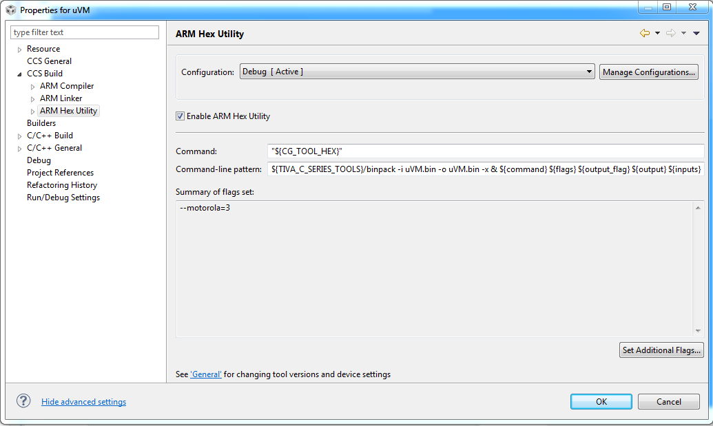
#define APP_START_ADDRESS       0x4000

however, the bootloader returns me T1F020100101. Last two digits indicates failure.

#define CAN_CMD_SUCCESS 0x00
#define CAN_CMD_FAIL 0x01

//
// Check for a valid starting address and image size.
//
if(!BL_FLASH_AD_CHECK_FN_HOOK(g_ui32TransferAddress,
g_ui32TransferSize))
{
//
// Set the code to an error to indicate that the last
// command failed. This informs the updater program
// that the download command failed.
//
ui8Status = CAN_CMD_FAIL;   // 

//
// This packet has been handled.
//
break;
}

it fails in above section of code in bl_can.c. It seems fails at Check for a valid starting address and image size. However, i checked the starting address and size. I did see any potential problem.

I have no clue what happened. I worked on stellaris CAN bootloader before and similar code. I do not have any issue.

Anyone has a hint?

Thanks in advance.

  • in bl_flash.c file, inside uint32_t BLInternalFlashStartAddrCheck(uint32_t ui32Addr, uint32_t ui32ImgSize) function, 

    if(((ui32Addr != APP_START_ADDRESS)) ||
    ((ui32Addr + ui32ImgSize) > ui32FlashSize) || ((ui32Addr & 3) != 0))
    {
    return(0);
    }

    (ui32Addr + ui32ImgSize) > ui32FlashSize) is true. 

    I check ui32FlashSize value is 0x00000800.

    Does ui32FlashSize = ((HWREG(SYSCTL_DC0) & SYSCTL_DC0_FLASHSZ_M) + 1) << 11 gives wrong value?

  • register SYSCTL_DC0 is only for stellaris series

    In Tiva C, SYSCTL_DC0 does NOT exist any more. 

    then, question is how does following code work

    //
    // Determine the size of the flash available on the part in use.
    //
    ui32FlashSize = ((HWREG(SYSCTL_DC0) & SYSCTL_DC0_FLASHSZ_M) + 1) << 11;

  • Hello Madoka,

    On TM4C129 device the Flash Size can be obtained from the FLASH_PP register

    Regards

    Amit

  • After having found this example, I figured I would add a little more clarity to the information above by stating the following:

    for a 129x part, include the following header files (should be included in bl_flash.c already):

    hw_sysctl.h for its define (SYSCTL_DC0_FLASHSZ_M)

    hw_flash.h for its define (FLASH_PP)


    and change the statement in bl_flash.c from:

    ui32FlashSize = ((HWREG(SYSCTL_DC0) & SYSCTL_DC0_FLASHSZ_M) + 1)

    to:

    ui32FlashSize = ((HWREG(FLASH_PP) & SYSCTL_DC0_FLASHSZ_M) + 1)

    with the recommendation that you don't change the boot loader library, but change a copy in your project and reference it instead.  I hope this helps others put this all together faster by handing the exact information and includes all in one post.


  • Hello Robert,

    There are a few more changes as well. This includes the way Serial Interfaces are configured on the TM4C129. The TM4C123 had the RCGC0-2 registers which have now been changed to RCGCx (x = peripheral name).

    Regards

    Amit

  • Amit,

    Good to know.  I am working with 129x series myself and wishing I had a CAN example for a bootloader to expedite my design.  Would you be aware of a full-blown example with application that I might tear into to verify if my design is heading down the right path?


    Thank you,

    Rob

  • Amit,

    I would like to know if there is a full example CAN bootloader application available.

    Thank you

    madoka

  • Hello Rob, Madoka,

    Do you mean a boot loader for CAN and it's corresponding PC or remote SW to send an image?

    For the first one. yes it is part of the existing flash based boot loader and is controlled by the bl_config.h. To the second part we do not have a PC side SW+it;s corresponding HW.

    Regards

    Amit

  • Amit,

    I'm interested in a checksum checking version to verify the functionality through example if possible and to see if the mailbox setup is the same as I do with the application, etc.  I have been working with the bl_config.h already, but some of the documentation around checksum usage and setup is quite vague in the following items:

    1. How and where do the 8 32 bit words get placed in thet interrupt vector table as I get warnings adding it on the end

    2. proper setup of binpack.exe in the post build steps as I am not a fan of how I place it just prior to the *.s37 file generation in my build steps through a command line "&".

    I am more than willing to provide a screenshot of step 2 and an example code snippet to verify that I'm on the right track on the above items.

    Interrupt Vector Table Code:

    //*****************************************************************************

    //

    // The vector table.  Note that the proper constructs must be placed on this to

    // ensure that it ends up at physical address 0x0000.0000 or at the start of

    // the program if located at a start address other than 0.

    //

    //*****************************************************************************

    #pragma

    DATA_SECTION(g_pfnVectors, ".intvecs")

    void

    (* const g_pfnVectors[])(void) =

    {

        (

    void (*)(void))((uint32_t)&__STACK_TOP),


    // The initial stack pointer

        ResetISR,                              

    // The reset handler

        NmiSR,                                 

    // The NMI handler

        FaultISR,                              

    // The hard fault handler

        IntDefaultHandler,                     

    // The MPU fault handler

        IntDefaultHandler,                     

    // The bus fault handler

        IntDefaultHandler,                     

    // The usage fault handler

        0,                                     

    // Reserved

        0,                                     

    // Reserved

        0,                                     

    // Reserved

        0,                                     

    // Reserved

        IntDefaultHandler,                     

    // SVCall handler

        IntDefaultHandler,                     

    // Debug monitor handler

        0,                                     

    // Reserved

        IntDefaultHandler,                     

    // The PendSV handler

        IntDefaultHandler,                     

    // The SysTick handler

        IntDefaultHandler,                     

    // GPIO Port A

        IntDefaultHandler,                     

    // GPIO Port B

        IntDefaultHandler,                     

    // GPIO Port C

        IntDefaultHandler,                     

    // GPIO Port D

        IntDefaultHandler,                     

    // GPIO Port E

        IntDefaultHandler,                     

    // UART0 Rx and Tx

        IntDefaultHandler,                     

    // UART1 Rx and Tx

        IntDefaultHandler,                     

    // SSI0 Rx and Tx

        IntDefaultHandler,                     

    // I2C0 Master and Slave

        IntDefaultHandler,                     

    // PWM Fault

        IntDefaultHandler,                     

    // PWM Generator 0

        IntDefaultHandler,                     

    // PWM Generator 1

        IntDefaultHandler,                     

    // PWM Generator 2

        IntDefaultHandler,                     

    // Quadrature Encoder 0

        IntDefaultHandler,                     

    // ADC Sequence 0

        IntDefaultHandler,                     

    // ADC Sequence 1

        IntDefaultHandler,                     

    // ADC Sequence 2

        IntDefaultHandler,                     

    // ADC Sequence 3

        WatchdogIntHandler,                     

    // Watchdog timer

        Timer0IntHandler,                     

    // Timer 0 subtimer A

        IntDefaultHandler,                     

    // Timer 0 subtimer B

        IntDefaultHandler,                     

    // Timer 1 subtimer A

        IntDefaultHandler,                     

    // Timer 1 subtimer B

        IntDefaultHandler,                     

    // Timer 2 subtimer A

        IntDefaultHandler,                     

    // Timer 2 subtimer B

        IntDefaultHandler,                     

    // Analog Comparator 0

        IntDefaultHandler,                     

    // Analog Comparator 1

        IntDefaultHandler,                     

    // Analog Comparator 2

        IntDefaultHandler,                     

    // System Control (PLL, OSC, BO)

        IntDefaultHandler,                     

    // FLASH Control

        IntDefaultHandler,                     

    // GPIO Port F

        IntDefaultHandler,                     

    // GPIO Port G

        IntDefaultHandler,                     

    // GPIO Port H

        IntDefaultHandler,                     

    // UART2 Rx and Tx

        IntDefaultHandler,                     

    // SSI1 Rx and Tx

        IntDefaultHandler,                     

    // Timer 3 subtimer A

        IntDefaultHandler,                     

    // Timer 3 subtimer B

        IntDefaultHandler,                     

    // I2C1 Master and Slave

        CAN0IntHandler,                     

    // CAN0

        IntDefaultHandler,                     

    // CAN1

        IntDefaultHandler,                     

    // Ethernet

        IntDefaultHandler,                     

    // Hibernate

        IntDefaultHandler,                     

    // USB0

        IntDefaultHandler,                     

    // PWM Generator 3

        IntDefaultHandler,                     

    // uDMA Software Transfer

        IntDefaultHandler,                     

    // uDMA Error

        IntDefaultHandler,                     

    // ADC1 Sequence 0

        IntDefaultHandler,                     

    // ADC1 Sequence 1

        IntDefaultHandler,                     

    // ADC1 Sequence 2

        IntDefaultHandler,                     

    // ADC1 Sequence 3

        IntDefaultHandler,                     

    // External Bus Interface 0

        IntDefaultHandler,                     

    // GPIO Port J

        IntDefaultHandler,                     

    // GPIO Port K

        IntDefaultHandler,                     

    // GPIO Port L

        IntDefaultHandler,                     

    // SSI2 Rx and Tx

        IntDefaultHandler,                     

    // SSI3 Rx and Tx

        IntDefaultHandler,                     

    // UART3 Rx and Tx

        IntDefaultHandler,                     

    // UART4 Rx and Tx

        IntDefaultHandler,                     

    // UART5 Rx and Tx

        IntDefaultHandler,                     

    // UART6 Rx and Tx

        IntDefaultHandler,                     

    // UART7 Rx and Tx

        IntDefaultHandler,                     

    // I2C2 Master and Slave

        IntDefaultHandler,                     

    // I2C3 Master and Slave

        IntDefaultHandler,                     

    // Timer 4 subtimer A

        IntDefaultHandler,                     

    // Timer 4 subtimer B

        IntDefaultHandler,                     

    // Timer 5 subtimer A

        IntDefaultHandler,                     

    // Timer 5 subtimer B

        IntDefaultHandler,                     

    // FPU

        0,                                     

    // Reserved

        0,                                     

    // Reserved

        IntDefaultHandler,                     

    // I2C4 Master and Slave

        IntDefaultHandler,                     

    // I2C5 Master and Slave

        IntDefaultHandler,                     

    // GPIO Port M

        IntDefaultHandler,                     

    // GPIO Port N

        0,                                     

    // Reserved

        IntDefaultHandler,                     

    // Tamper

        IntDefaultHandler,                     

    // GPIO Port P (Summary or P0)

        IntDefaultHandler,                     

    // GPIO Port P1

        IntDefaultHandler,                     

    // GPIO Port P2

        IntDefaultHandler,                     

    // GPIO Port P3

        IntDefaultHandler,                     

    // GPIO Port P4

        IntDefaultHandler,                     

    // GPIO Port P5

        IntDefaultHandler,                     

    // GPIO Port P6

        IntDefaultHandler,                     

    // GPIO Port P7

        IntDefaultHandler,                     

    // GPIO Port Q (Summary or Q0)

        IntDefaultHandler,                     

    // GPIO Port Q1

        IntDefaultHandler,                     

    // GPIO Port Q2

        IntDefaultHandler,                     

    // GPIO Port Q3

        IntDefaultHandler,                     

    // GPIO Port Q4

        IntDefaultHandler,                     

    // GPIO Port Q5

        IntDefaultHandler,                     

    // GPIO Port Q6

        IntDefaultHandler,                     

    // GPIO Port Q7

        IntDefaultHandler,                     

    // GPIO Port R

        IntDefaultHandler,                     

    // GPIO Port S

        IntDefaultHandler,                     

    // SHA/MD5 0

        IntDefaultHandler,                     

    // AES 0

        IntDefaultHandler,                     

    // DES3DES 0

        IntDefaultHandler,                     

    // LCD Controller 0

        IntDefaultHandler,                     

    // Timer 6 subtimer A

        IntDefaultHandler,                     

    // Timer 6 subtimer B

        IntDefaultHandler,                     

    // Timer 7 subtimer A

        IntDefaultHandler,                     

    // Timer 7 subtimer B

        IntDefaultHandler,                     

    // I2C6 Master and Slave

        IntDefaultHandler,                     

    // I2C7 Master and Slave

        IntDefaultHandler,                     

    // HIM Scan Matrix Keyboard 0

        IntDefaultHandler,                     

    // One Wire 0

        IntDefaultHandler,                     

    // HIM PS/2 0

        IntDefaultHandler,                     

    // HIM LED Sequencer 0

        IntDefaultHandler,                     

    // HIM Consumer IR 0

        IntDefaultHandler,                     

    // I2C8 Master and Slave

        IntDefaultHandler,                     

    // I2C9 Master and Slave

        IntDefaultHandler,                     

    // GPIO Port T

        IntDefaultHandler,                     

    // Fan 1

        0,                                     

    // Reserved

        0xFF01FF02,

        0xFF03FF04,

        0x00000000,

        0x00000000,

        0xFFFFFFFF,

        0xFFFFFFFF,

        0xFFFFFFFF,

        0xFFFFFFFF

    };

    Processor in use:

    TM4C1290NCPDT


     Screenshot of build step:


  • Hello Robert,

    1. The interrupt vector has to be defined as

        IntDefaultHandler,                      // PWM 1 Fault
        (void (*)(void))0xFF01FF02,
        (void (*)(void))0xFF03FF04,
        0x00000000,
        0x00000000,
        (void (*)(void))0xFFFFFFFF,
        (void (*)(void))0xFFFFFFFF,
        (void (*)(void))0xFFFFFFFF,
        (void (*)(void))0xFFFFFFFF

    2. I generally run the binpack.exe as a command line utility and then use this modified firmware image.

    binpack.exe -i blink_test.bin -o blink_out.bin -a 0x2800

    I hope that clarifies. To double check if you run a binary reader like "od" in linux (must have cygwin version as well, then you will see the inserted 8 words in the original and the CRC updated 8 words in the modified file

    Regards

    Amit

  • Thanks for the casting portion there. It is good to know I was on the right path with warnings, but I guess I will have to either go with a two step process or continue with the above command line method (which appears to work, but I was hoping for a better method). When work slows down (doubtful at this rate), I'll post a generic CAN bootloader example for 129x.