


I want to learn how to use i2c protocol on ti launchpad. I have an rtc ds1307. I have setup a project. I want to setup the control register for1 Hz square pulse that i can see blinking on the pcb.
After a lot o effort that the program was stacking into the check of i2cmasterbusy() function i enabled the loopback mode and the program unstacked.
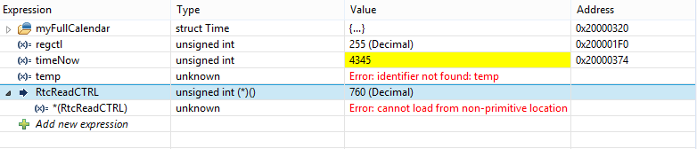
The problem was not solved tho. In the debug mode the i2creceive funtion gives price of 760 in decimal.the variable that is set to the retrurn of the function goes from zero to 255. I will give you the 2 photos of the program and the whole program. If you find any problem please tell me what i do wrong.
The photos:

The code is in files main.c,delaysetup.c, i2c.c,rtc.c
I ma not giveing the delaysetup cuse is just the interupt of timer0 and the delay function.
I2c.c is:
#include "i2c.h"
#include <stdbool.h>
#include <stdarg.h>
#include <stdint.h>
#include "driverlib/sysctl.h"
#include "driverlib/gpio.h"
#include "driverlib/i2c.h"
#include "driverlib/pin_map.h"
#include "inc/hw_types.h"
#include "inc/hw_memmap.h"
#include "inc/hw_gpio.h"
#include "inc/hw_i2c.h"


void InitI2C0(void)
{
    //enable GPIO peripheral that contains I2C 0
    SysCtlPeripheralEnable(SYSCTL_PERIPH_GPIOB);

    //enable I2C module 0
    SysCtlPeripheralEnable(SYSCTL_PERIPH_I2C0);

    //reset module
    SysCtlPeripheralReset(SYSCTL_PERIPH_I2C0);

    // Configure the pin muxing for I2C0 functions on port B2 and B3.
    GPIOPinConfigure(GPIO_PB2_I2C0SCL);
    GPIOPinConfigure(GPIO_PB3_I2C0SDA);


    // Select the I2C function for these pins.
    GPIOPinTypeI2CSCL(GPIO_PORTB_BASE, GPIO_PIN_2);
    GPIOPinTypeI2C(GPIO_PORTB_BASE,  GPIO_PIN_3);

    // Enable and initialize the I2C0 master module.  Use the system clock for
    // the I2C0 module.  The last parameter sets the I2C data transfer rate.
    // If false the data rate is set to 100kbps and if true the data rate will
    // be set to 400kbps.
    I2CMasterInitExpClk(I2C0_BASE, SysCtlClockGet(), false);

    // Enable loopback mode.  Loopback mode is a built in feature that is
    // useful for debugging I2C operations.  It internally connects the I2C
    // master and slave terminals, which effectively let's you send data as
    // a master and receive data as a slave.
    // NOTE: For external I2C operation you will need to use external pullups
    // that are stronger than the internal pullups.  Refer to the datasheet for
    // more information.
    //
    HWREG(I2C0_BASE + I2C_O_MCR) |= 0x01;

    //clear I2C FIFOs
    HWREG(I2C0_BASE + I2C_O_FIFOCTL) = 80008000;
}

void I2CSend2(uint8_t slave_addr,uint8_t send_reg_addr,uint8_t send_value){


	I2CMasterSlaveAddrSet(I2C0_BASE,slave_addr,false);

	I2CMasterDataPut(I2C0_BASE,send_reg_addr);

	I2CMasterControl(I2C0_BASE,I2C_MASTER_CMD_SINGLE_SEND);

	while(I2CMasterBusy(I2C0_BASE)){

	}

	I2CMasterDataPut(I2C0_BASE,send_value);

	I2CMasterControl(I2C0_BASE,I2C_MASTER_CMD_SINGLE_SEND);

	while(I2CMasterBusy(I2C0_BASE)){

	}

}


//sends an I2C command to the specified slave
void I2CSend(uint8_t slave_addr, uint8_t num_of_args, ...)
{
	//    Tell the master module what address it will place on the bus when
	//    communicating with the slave.
	I2CMasterSlaveAddrSet(I2C0_BASE, slave_addr, false);

	//stores list of variable number of arguments
	va_list vargs;

	//specifies the va_list to "open" and the last fixed argument
	//so vargs knows where to start looking
	va_start(vargs, num_of_args);

	//put data to be sent into FIFO
	I2CMasterDataPut(I2C0_BASE, va_arg(vargs, uint32_t));

	//if there is only one argument, we only need to use the
	//single send I2C function
	if(num_of_args == 1)
	{
		//Initiate send of data from the MCU
		I2CMasterControl(I2C0_BASE, I2C_MASTER_CMD_SINGLE_SEND);

		// Wait until MCU is done transferring.
		while(I2CMasterBusy(I2C0_BASE));

		//"close" variable argument list
		va_end(vargs);
	}

	//otherwise, we start transmission of multiple bytes on the
	//I2C bus
	else
	{
		//Initiate send of data from the MCU
		I2CMasterControl(I2C0_BASE, I2C_MASTER_CMD_BURST_SEND_START);

		// Wait until MCU is done transferring.
		while(I2CMasterBusy(I2C0_BASE));

		//send num_of_args-2 pieces of data, using the
		//BURST_SEND_CONT command of the I2C module
		uint8_t i;
		for(i = 1 ; i < (num_of_args - 1) ; i++)
		{
			//put next piece of data into I2C FIFO
			I2CMasterDataPut(I2C0_BASE, va_arg(vargs, uint32_t));
			//send next data that was just placed into FIFO
			I2CMasterControl(I2C0_BASE, I2C_MASTER_CMD_BURST_SEND_CONT);

			// Wait until MCU is done transferring.
			while(I2CMasterBusy(I2C0_BASE));
		}

		//put last piece of data into I2C FIFO
		I2CMasterDataPut(I2C0_BASE, va_arg(vargs, uint32_t));
		//send next data that was just placed into FIFO
		I2CMasterControl(I2C0_BASE, I2C_MASTER_CMD_BURST_SEND_FINISH);
		// Wait until MCU is done transferring.
		while(I2CMasterBusy(I2C0_BASE));

		//"close" variable args list
		va_end(vargs);
	}
}


//sends an array of data via I2C to the specified slave
void I2CSendString(uint32_t slave_addr, char array[])
{
    // Tell the master module what address it will place on the bus when
    // communicating with the slave.
    I2CMasterSlaveAddrSet(I2C0_BASE, slave_addr, false);

    //put data to be sent into FIFO
    I2CMasterDataPut(I2C0_BASE, array[0]);

    //if there is only one argument, we only need to use the
    //single send I2C function
    if(array[1] == '\0')
    {
        //Initiate send of data from the MCU
        I2CMasterControl(I2C0_BASE, I2C_MASTER_CMD_SINGLE_SEND);

        // Wait until MCU is done transferring.
        while(I2CMasterBusy(I2C0_BASE));
    }

    //otherwise, we start transmission of multiple bytes on the
    //I2C bus
    else
    {
        //Initiate send of data from the MCU
        I2CMasterControl(I2C0_BASE, I2C_MASTER_CMD_BURST_SEND_START);

        // Wait until MCU is done transferring.
        while(I2CMasterBusy(I2C0_BASE));

        //initialize index into array
        uint8_t i = 1;

        //send num_of_args-2 pieces of data, using the
        //BURST_SEND_CONT command of the I2C module
        while(array[i + 1] != '\0')
        {
            //put next piece of data into I2C FIFO
            I2CMasterDataPut(I2C0_BASE, array[i++]);

            //send next data that was just placed into FIFO
            I2CMasterControl(I2C0_BASE, I2C_MASTER_CMD_BURST_SEND_CONT);

            // Wait until MCU is done transferring.
            while(I2CMasterBusy(I2C0_BASE));
        }

        //put last piece of data into I2C FIFO
        I2CMasterDataPut(I2C0_BASE, array[i]);

        //send next data that was just placed into FIFO
        I2CMasterControl(I2C0_BASE, I2C_MASTER_CMD_BURST_SEND_FINISH);

        // Wait until MCU is done transferring.
        while(I2CMasterBusy(I2C0_BASE));
    }
}


uint32_t I2CReceive2(uint32_t slave_addr,uint8_t reg){


	I2CMasterSlaveAddrSet(I2C0_BASE,slave_addr,false);

	I2CMasterDataPut(I2C0_BASE,reg);

	I2CMasterControl(I2C0_BASE,I2C_MASTER_CMD_SINGLE_SEND);

	while(I2CMasterBusy(I2C0_BASE)){

	}

	I2CMasterSlaveAddrSet(I2C0_BASE,slave_addr,true);

	I2CMasterControl(I2C0_BASE,I2C_MASTER_CMD_SINGLE_RECEIVE);

	while(I2CMasterBusy(I2C0_BASE)){

	}

	return I2CMasterDataGet(I2C0_BASE);
}


//read specified register on slave device
uint32_t I2CReceive(uint32_t slave_addr, uint8_t reg)
{
    //specify that we are writing (a register address) to the
    //slave device
    I2CMasterSlaveAddrSet(I2C0_BASE, slave_addr, false);

    //specify register to be read
    I2CMasterDataPut(I2C0_BASE, reg);

    //send control byte and register address byte to slave device
    I2CMasterControl(I2C0_BASE, I2C_MASTER_CMD_BURST_SEND_START);

    //wait for MCU to finish transaction
    while(I2CMasterBusy(I2C0_BASE));

    //specify that we are going to read from slave device
    I2CMasterSlaveAddrSet(I2C0_BASE, slave_addr, true );

    //send control byte and read from the register we
    //specified
    I2CMasterControl(I2C0_BASE, I2C_MASTER_CMD_SINGLE_RECEIVE);

    //wait for MCU to finish transaction
    while(I2CMasterBusy(I2C0_BASE));

    //return data pulled from the specified register
    return I2CMasterDataGet(I2C0_BASE);
}
The RTC.c is:
#include "RTC.h"
#include "stdbool.h"
#include <stdint.h>
#include "i2c.h"
#include "time.h"

#define DS1307_ADDRESS  0x68
#define DS1307_CONTROL  0x07
#define DS1307_NVRAM    0x08
#define SECONDS_PER_DAY 86400L
#define OneHertzSQP 0x10
#define pgm_read_byte(addr) (*(const unsigned char *)(addr))

#define SECONDS_FROM_1970_TO_2000 946684800


const uint8_t daysInMonth [] = { 31,28,31,30,31,30,31,31,30,31,30,31 };


uint8_t bcd2bin (uint8_t val) {
	return val - 6 * (val >> 4);
}

uint8_t bin2bcd (uint8_t val) {
	return val + 6 * (val / 10);
}

void RtcDS1307adjust(){

	I2CSend(DS1307_ADDRESS,7,
			myFullCalendar.seconds,myFullCalendar.minutes,myFullCalendar.hour,
			myFullCalendar.dayOfWeek,myFullCalendar.date,myFullCalendar.month,myFullCalendar.year);

}

void RtcSetCTRL(){

    I2CSend(DS1307_ADDRESS,2,DS1307_CONTROL,OneHertzSQP);
//	I2CSend2(DS1307_ADDRESS,DS1307_CONTROL,OneHertzSQP);

}

uint32_t RtcReadCTRL()
{
	return I2CReceive(DS1307_ADDRESS,DS1307_CONTROL);

	//return I2CReceive2(DS1307_ADDRESS,DS1307_CONTROL);
}

void RtcSetTimeStruct2(const char* date, const char* time){


	    // sample input: date = "Dec 26 2009", time = "12:34:56"
	    myFullCalendar.yearOff = conv2d(date + 9);
	    myFullCalendar.year=2000+myFullCalendar.yearOff;


	    // Jan Feb Mar Apr May Jun Jul Aug Sep Oct Nov Dec
	    switch (date[0]) {
	        case 'J':
	        {
	        	if( date[1] == 'a'){
	        		myFullCalendar.month=1;
	        	}else if (date[2]=='n'){
	        		myFullCalendar.month=6;
	        	}else{
	        		myFullCalendar.month=7;
	        	}
	        }
	        break;

	        case 'F': myFullCalendar.month = 2; break;

	        case 'A':
	        {
	        	if (date[2]=='r'){
	        		myFullCalendar.month=4;
	        	}else{
	        		myFullCalendar.month=8;
	        	}
	        }
	        break;

	        case 'M':
	        {
	        	if (date[2]=='r'){
	        		myFullCalendar.month=3;
	        	}else{
	        		myFullCalendar.month=5;
	        	}
	        }
	        break;

	        case 'S': myFullCalendar.month= 9; break;
	        case 'O': myFullCalendar.month= 10; break;
	        case 'N': myFullCalendar.month= 11; break;
	        case 'D': myFullCalendar.month= 12; break;
	    }

	    myFullCalendar.date = conv2d(date + 4);
	    myFullCalendar.hour = conv2d(time);
	    myFullCalendar.minutes = conv2d(time + 3);
	    myFullCalendar.seconds = conv2d(time + 6);
	    myFullCalendar.dayOfWeek = RtcDayOfWeek();
}

void RtcSetTimeStruct(){

	time_t rawtime;
	struct tm *timeStruct;
	rawtime=time(0);
	timeStruct=localtime(&rawtime);
	myFullCalendar.seconds=timeStruct->tm_sec;
	myFullCalendar.minutes=timeStruct->tm_min;
	myFullCalendar.hour=timeStruct->tm_hour;
	myFullCalendar.date=timeStruct->tm_mday;
	myFullCalendar.month=timeStruct->tm_mon;
	myFullCalendar.year=timeStruct->tm_year+1900;

	myFullCalendar.yearOff=(myFullCalendar.year)-2000;
	myFullCalendar.dayOfWeek=timeStruct->tm_wday;

}
uint8_t RtcDayOfWeek(){
    uint16_t day = date2days(myFullCalendar.yearOff,myFullCalendar.month,myFullCalendar.date);
    return (day + 6) % 7; // Jan 1, 2000 is a Saturday, i.e. returns 6
}


uint8_t conv2d(const char* p) {
    uint8_t v = 0;
    if ('0' <= *p && *p <= '9')
        v = *p - '0';
    return 10 * v + *++p - '0';
}

uint16_t date2days(uint16_t y, uint8_t m, uint8_t d) {
    if (y >= 2000)
        y -= 2000;
    uint16_t days = d;
    uint8_t i;
    for (i = 1; i < m; ++i)
        days += pgm_read_byte(daysInMonth + i - 1);
    if (m > 2 && y % 4 == 0)
        ++days;
    return days + 365 * y + (y + 3) / 4 - 1;
}
And my main.c
#include "stdint.h"
#include "stdbool.h"
#include  <stdarg.h>
#include "inc/hw_memmap.h"
#include "inc/hw_types.h"
#include "inc/hw_i2c.h"
#include "inc/hw_gpio.h"
#include "driverlib/i2c.h"
#include "driverlib/gpio.h"
#include "driverlib/sysctl.h"
#include "driverlib/pin_map.h"
#include "DelaySetup.h"
#include "driverlib/timer.h"
#include "driverlib/interrupt.h"
#include "inc/tm4c123gh6pm.h"

#include "libs/RTC.h"
#include "libs/DelaySetup.h"
#include "libs/i2c.h"

int main(void) {


	SysCtlClockSet(SYSCTL_SYSDIV_5|SYSCTL_USE_PLL|SYSCTL_XTAL_16MHZ|SYSCTL_OSC_MAIN);
	uint32_t regctl;


	SysCtlPeripheralEnable(SYSCTL_PERIPH_GPIOF);
	SysCtlPeripheralEnable(SYSCTL_PERIPH_TIMER0);


	TimerConfigure(TIMER0_BASE,TIMER_CFG_A_PERIODIC);

	uint32_t periodLoad;

	periodLoad = (SysCtlClockGet() / 1000);
	TimerLoadSet(TIMER0_BASE,TIMER_A,periodLoad);
	IntEnable(INT_TIMER0A);
	TimerIntEnable(TIMER0_BASE,TIMER_TIMA_TIMEOUT);
	IntMasterEnable();
	TimerEnable(TIMER0_BASE,TIMER_A);

	GPIOPinTypeGPIOOutput(GPIO_PORTF_BASE,GPIO_PIN_1|GPIO_PIN_2|GPIO_PIN_3);
	InitI2C0();
//	RtcSetTimeStruct();
//	RtcDS1307adjust();
	RtcSetCTRL();


	regctl=RtcReadCTRL();

	while(1) {
		if(GPIOPinRead(GPIO_PORTF_BASE, GPIO_PIN_2))  {
			GPIOPinWrite(GPIO_PORTF_BASE, GPIO_PIN_2, 0);
			delayms(100);
		}else{
			GPIOPinWrite(GPIO_PORTF_BASE, GPIO_PIN_2, 4);
			delayms(100);
		}

	}

}
Can you give me the error???
The last files.DelaySetup.c
#include "DelaySetup.h"
#include "driverlib/timer.h"
#include "inc/hw_memmap.h"


volatile uint32_t timeNow=0;

void Timer0IntHandler(void) {
	// Clear the timer interrupt
	uint32_t status=TimerIntStatus(TIMER0_BASE,true);
	TimerIntClear(TIMER0_BASE, status);
	timeNow++;

	// Read the current state of the GPIO pin and
	// write back the opposite state
//	if(GPIOPinRead(GPIO_PORTF_BASE, GPIO_PIN_2))  {
//		GPIOPinWrite(GPIO_PORTF_BASE, GPIO_PIN_1|GPIO_PIN_2|GPIO_PIN_3, 0);
//	}  else  {
//		GPIOPinWrite(GPIO_PORTF_BASE, GPIO_PIN_2, 4);
//	}

}


void delayms(uint32_t timeInMSEC){
	volatile uint32_t temp=timeNow;
	while ((timeNow-temp)<timeInMSEC){

	}
}
And the startup file
//*****************************************************************************
//
// Startup code for use with TI's Code Composer Studio.
//
// Copyright (c) 2011-2014 Texas Instruments Incorporated.  All rights reserved.
// Software License Agreement
//
// Software License Agreement
//
// Texas Instruments (TI) is supplying this software for use solely and
// exclusively on TI's microcontroller products. The software is owned by
// TI and/or its suppliers, and is protected under applicable copyright
// laws. You may not combine this software with "viral" open-source
// software in order to form a larger program.
//
// THIS SOFTWARE IS PROVIDED "AS IS" AND WITH ALL FAULTS.
// NO WARRANTIES, WHETHER EXPRESS, IMPLIED OR STATUTORY, INCLUDING, BUT
// NOT LIMITED TO, IMPLIED WARRANTIES OF MERCHANTABILITY AND FITNESS FOR
// A PARTICULAR PURPOSE APPLY TO THIS SOFTWARE. TI SHALL NOT, UNDER ANY
// CIRCUMSTANCES, BE LIABLE FOR SPECIAL, INCIDENTAL, OR CONSEQUENTIAL
// DAMAGES, FOR ANY REASON WHATSOEVER.
//
//*****************************************************************************

#include <stdint.h>

//*****************************************************************************
//
// Forward declaration of the default fault handlers.
//
//*****************************************************************************
void ResetISR(void);
static void NmiSR(void);
static void FaultISR(void);
static void IntDefaultHandler(void);

//*****************************************************************************
//
// External declaration for the reset handler that is to be called when the
// processor is started
//
//*****************************************************************************
extern void _c_int00(void);
extern void Timer0IntHandler(void);
//*****************************************************************************
//
// Linker variable that marks the top of the stack.
//
//*****************************************************************************
extern uint32_t __STACK_TOP;

//*****************************************************************************
//
// External declarations for the interrupt handlers used by the application.
//
//*****************************************************************************
// To be added by user

//*****************************************************************************
//
// The vector table.  Note that the proper constructs must be placed on this to
// ensure that it ends up at physical address 0x0000.0000 or at the start of
// the program if located at a start address other than 0.
//
//*****************************************************************************
#pragma DATA_SECTION(g_pfnVectors, ".intvecs")
void (* const g_pfnVectors[])(void) =
{
    (void (*)(void))((uint32_t)&__STACK_TOP),
                                            // The initial stack pointer
    ResetISR,                               // The reset handler
    NmiSR,                                  // The NMI handler
    FaultISR,                               // The hard fault handler
    IntDefaultHandler,                      // The MPU fault handler
    IntDefaultHandler,                      // The bus fault handler
    IntDefaultHandler,                      // The usage fault handler
    0,                                      // Reserved
    0,                                      // Reserved
    0,                                      // Reserved
    0,                                      // Reserved
    IntDefaultHandler,                      // SVCall handler
    IntDefaultHandler,                      // Debug monitor handler
    0,                                      // Reserved
    IntDefaultHandler,                      // The PendSV handler
    IntDefaultHandler,                      // The SysTick handler
    IntDefaultHandler,                      // GPIO Port A
    IntDefaultHandler,                      // GPIO Port B
    IntDefaultHandler,                      // GPIO Port C
    IntDefaultHandler,                      // GPIO Port D
    IntDefaultHandler,                      // GPIO Port E
    IntDefaultHandler,                      // UART0 Rx and Tx
    IntDefaultHandler,                      // UART1 Rx and Tx
    IntDefaultHandler,                      // SSI0 Rx and Tx
    IntDefaultHandler,                      // I2C0 Master and Slave
    IntDefaultHandler,                      // PWM Fault
    IntDefaultHandler,                      // PWM Generator 0
    IntDefaultHandler,                      // PWM Generator 1
    IntDefaultHandler,                      // PWM Generator 2
    IntDefaultHandler,                      // Quadrature Encoder 0
    IntDefaultHandler,                      // ADC Sequence 0
    IntDefaultHandler,                      // ADC Sequence 1
    IntDefaultHandler,                      // ADC Sequence 2
    IntDefaultHandler,                      // ADC Sequence 3
    IntDefaultHandler,                      // Watchdog timer
    Timer0IntHandler,                      // Timer 0 subtimer A
    IntDefaultHandler,                      // Timer 0 subtimer B
    IntDefaultHandler,                      // Timer 1 subtimer A
    IntDefaultHandler,                      // Timer 1 subtimer B
    IntDefaultHandler,                      // Timer 2 subtimer A
    IntDefaultHandler,                      // Timer 2 subtimer B
    IntDefaultHandler,                      // Analog Comparator 0
    IntDefaultHandler,                      // Analog Comparator 1
    IntDefaultHandler,                      // Analog Comparator 2
    IntDefaultHandler,                      // System Control (PLL, OSC, BO)
    IntDefaultHandler,                      // FLASH Control
    IntDefaultHandler,                      // GPIO Port F
    IntDefaultHandler,                      // GPIO Port G
    IntDefaultHandler,                      // GPIO Port H
    IntDefaultHandler,                      // UART2 Rx and Tx
    IntDefaultHandler,                      // SSI1 Rx and Tx
    IntDefaultHandler,                      // Timer 3 subtimer A
    IntDefaultHandler,                      // Timer 3 subtimer B
    IntDefaultHandler,                      // I2C1 Master and Slave
    IntDefaultHandler,                      // Quadrature Encoder 1
    IntDefaultHandler,                      // CAN0
    IntDefaultHandler,                      // CAN1
    0,                                      // Reserved
    0,                                      // Reserved
    IntDefaultHandler,                      // Hibernate
    IntDefaultHandler,                      // USB0
    IntDefaultHandler,                      // PWM Generator 3
    IntDefaultHandler,                      // uDMA Software Transfer
    IntDefaultHandler,                      // uDMA Error
    IntDefaultHandler,                      // ADC1 Sequence 0
    IntDefaultHandler,                      // ADC1 Sequence 1
    IntDefaultHandler,                      // ADC1 Sequence 2
    IntDefaultHandler,                      // ADC1 Sequence 3
    0,                                      // Reserved
    0,                                      // Reserved
    IntDefaultHandler,                      // GPIO Port J
    IntDefaultHandler,                      // GPIO Port K
    IntDefaultHandler,                      // GPIO Port L
    IntDefaultHandler,                      // SSI2 Rx and Tx
    IntDefaultHandler,                      // SSI3 Rx and Tx
    IntDefaultHandler,                      // UART3 Rx and Tx
    IntDefaultHandler,                      // UART4 Rx and Tx
    IntDefaultHandler,                      // UART5 Rx and Tx
    IntDefaultHandler,                      // UART6 Rx and Tx
    IntDefaultHandler,                      // UART7 Rx and Tx
    0,                                      // Reserved
    0,                                      // Reserved
    0,                                      // Reserved
    0,                                      // Reserved
    IntDefaultHandler,                      // I2C2 Master and Slave
    IntDefaultHandler,                      // I2C3 Master and Slave
    IntDefaultHandler,                      // Timer 4 subtimer A
    IntDefaultHandler,                      // Timer 4 subtimer B
    0,                                      // Reserved
    0,                                      // Reserved
    0,                                      // Reserved
    0,                                      // Reserved
    0,                                      // Reserved
    0,                                      // Reserved
    0,                                      // Reserved
    0,                                      // Reserved
    0,                                      // Reserved
    0,                                      // Reserved
    0,                                      // Reserved
    0,                                      // Reserved
    0,                                      // Reserved
    0,                                      // Reserved
    0,                                      // Reserved
    0,                                      // Reserved
    0,                                      // Reserved
    0,                                      // Reserved
    0,                                      // Reserved
    0,                                      // Reserved
    IntDefaultHandler,                      // Timer 5 subtimer A
    IntDefaultHandler,                      // Timer 5 subtimer B
    IntDefaultHandler,                      // Wide Timer 0 subtimer A
    IntDefaultHandler,                      // Wide Timer 0 subtimer B
    IntDefaultHandler,                      // Wide Timer 1 subtimer A
    IntDefaultHandler,                      // Wide Timer 1 subtimer B
    IntDefaultHandler,                      // Wide Timer 2 subtimer A
    IntDefaultHandler,                      // Wide Timer 2 subtimer B
    IntDefaultHandler,                      // Wide Timer 3 subtimer A
    IntDefaultHandler,                      // Wide Timer 3 subtimer B
    IntDefaultHandler,                      // Wide Timer 4 subtimer A
    IntDefaultHandler,                      // Wide Timer 4 subtimer B
    IntDefaultHandler,                      // Wide Timer 5 subtimer A
    IntDefaultHandler,                      // Wide Timer 5 subtimer B
    IntDefaultHandler,                      // FPU
    0,                                      // Reserved
    0,                                      // Reserved
    IntDefaultHandler,                      // I2C4 Master and Slave
    IntDefaultHandler,                      // I2C5 Master and Slave
    IntDefaultHandler,                      // GPIO Port M
    IntDefaultHandler,                      // GPIO Port N
    IntDefaultHandler,                      // Quadrature Encoder 2
    0,                                      // Reserved
    0,                                      // Reserved
    IntDefaultHandler,                      // GPIO Port P (Summary or P0)
    IntDefaultHandler,                      // GPIO Port P1
    IntDefaultHandler,                      // GPIO Port P2
    IntDefaultHandler,                      // GPIO Port P3
    IntDefaultHandler,                      // GPIO Port P4
    IntDefaultHandler,                      // GPIO Port P5
    IntDefaultHandler,                      // GPIO Port P6
    IntDefaultHandler,                      // GPIO Port P7
    IntDefaultHandler,                      // GPIO Port Q (Summary or Q0)
    IntDefaultHandler,                      // GPIO Port Q1
    IntDefaultHandler,                      // GPIO Port Q2
    IntDefaultHandler,                      // GPIO Port Q3
    IntDefaultHandler,                      // GPIO Port Q4
    IntDefaultHandler,                      // GPIO Port Q5
    IntDefaultHandler,                      // GPIO Port Q6
    IntDefaultHandler,                      // GPIO Port Q7
    IntDefaultHandler,                      // GPIO Port R
    IntDefaultHandler,                      // GPIO Port S
    IntDefaultHandler,                      // PWM 1 Generator 0
    IntDefaultHandler,                      // PWM 1 Generator 1
    IntDefaultHandler,                      // PWM 1 Generator 2
    IntDefaultHandler,                      // PWM 1 Generator 3
    IntDefaultHandler                       // PWM 1 Fault
};

//*****************************************************************************
//
// This is the code that gets called when the processor first starts execution
// following a reset event.  Only the absolutely necessary set is performed,
// after which the application supplied entry() routine is called.  Any fancy
// actions (such as making decisions based on the reset cause register, and
// resetting the bits in that register) are left solely in the hands of the
// application.
//
//*****************************************************************************
void
ResetISR(void)
{
    //
    // Jump to the CCS C initialization routine.  This will enable the
    // floating-point unit as well, so that does not need to be done here.
    //
    __asm("    .global _c_int00\n"
          "    b.w     _c_int00");
}

//*****************************************************************************
//
// This is the code that gets called when the processor receives a NMI.  This
// simply enters an infinite loop, preserving the system state for examination
// by a debugger.
//
//*****************************************************************************
static void
NmiSR(void)
{
    //
    // Enter an infinite loop.
    //
    while(1)
    {
    }
}

//*****************************************************************************
//
// This is the code that gets called when the processor receives a fault
// interrupt.  This simply enters an infinite loop, preserving the system state
// for examination by a debugger.
//
//*****************************************************************************
static void
FaultISR(void)
{
    //
    // Enter an infinite loop.
    //
    while(1)
    {
    }
}

//*****************************************************************************
//
// This is the code that gets called when the processor receives an unexpected
// interrupt.  This simply enters an infinite loop, preserving the system state
// for examination by a debugger.
//
//*****************************************************************************
static void
IntDefaultHandler(void)
{
    //
    // Go into an infinite loop.
    //
    while(1)
    {
    }
}


