This thread has been locked.

If you have a related question, please click the "Ask a related question" button in the top right corner. The newly created question will be automatically linked to this question.

Programming Error 0x1 using TM4C123GH6PGE

Other Parts Discussed in Thread: LMFLASHPROGRAMMER, TM4C129ENCPDT

Hello,

I am facing Programming error 0x1 in LMFlasher

I have a custom board on which i have attached the JTAG headers and trying to program it. I am using DK-TM4C123G Development Board.

I am able to communicate with the processor and do all the other things present in the LMFlasher like Blank Check, Read the ROM and set MAC Address but as soon I use it to upload the program it says Programming Error 0x1 and stops.

The status led of ICDI on the development board remains continuously ON. I have to remove the plug and reset it to make it functional again.

Can anyone point out what I could be missing??? The following are the connections I have made to the micro-controller

All the VDD Pins Connected

All the GND Pins connected

16 Mhz Crystal connected

VDDA connected

I am getting 1.2 volts on the VDDC

Also I would like to tell that I have already tried with lots of JTAG programming frequencies from 100Hz to 1 MHz

Thanks in advance

  • Hello Ashish

    So you are using the ICDI from the DK-TM4C123 as a programmer for your custom board. Is that correct?

    You mentioned that you are able to read the ROM and exactly what you are doing to read the ROM? This is more out of curiosity but may be useful information.

    Also are there pull up on the JTAG lines between the two devices?

    Regards
    Amit
  • Hello Amit,

    Thanks for your response. Yes I am using DK-TM4C123 as a programmer for my custom board.

    Yes I am using Pull Up via 10K Resistors on all the JTAG Lines.  

    In order to read the ROM from the board I used the LMFlash Programmer Tool and clicked on the upload button. It starts reading via JTAG and nicely uploads ROM data to the computer. 

    I don't know if this might be a useful information : What I can notice is that Erasing of the ROM is done properly but as soon as it comes to the Programming it gives an error.

    Thanks,

    Ashish

  • Hello Ashish,

    Let me first clarify the nomenclature. ROM and Flash are physically different memories. The ROM can only be read and not erased nor programmed by a customer, while Flash can be programmed, erased and read.

    Now when you upload the "ROM" (nomenclature confusion pending) what is the value you see in a binary reader? Is it all 1's in the bits.

    Also there is lack of clarity on how DK-TM4C123 has been rewired to the custom board, as you may be seeing an issue due to conflicting TDO's from two devices.

    Regards
    Amit
  • Hello Amit,

    Sorry my mistake by ROM I mean the Flash Memory and not ROM Memory.

    I have installed the JP1 Jumper which is Enable External Debugging and connected TDI, TDO, TCK and TMS to the device.

    Now so far this is what I have tried:
    I have 3 Development Boards - so I thought of taking 1 board for some more debugging

    I removed the Onboard Processor so that their is no conflict between my device and the onboard device. I connected Reset Pin (90) to the JTAG pin 10

    Also I thought it might be the issue of the processor so I changed to another one; but alas! again the same result

    Again its still working the same manner :(

    When I read data from the Flash - it is all blank i.e all 1's


    Thanks,
    Ashish

  • Hello Ashish,

    Connections seem fine and part of it is working. Can you check if the LaunchPad which is working as a debugger is connected to a USB3.0 port.See below posts for more details.

    http://e2e.ti.com/support/microcontrollers/tiva_arm/f/908/t/294634

    Also you have mentioned that you are able to program the User registers (MAC registers) and read back the value Can you write some junk value to the LMFlashProgrammer (not to the end device) and ask for read back to ensure that it is not an artifact of the LMFlashProgrammer.

    Regards
    Amit
  • Dear Amit,

    Thanks for your response.

    I committed the MAC Registers and then closed the LMFlashProgrammer, again opened it and re-read them from the processor. They were properly written.

    I tried Swapping between USB 2.0 and 3.0 without any luck whatsoever.

    What do you think the possible scenarios can be where Erasing, Reading are being done properly but not writing ?

    Moreover I don't have the launchpad its the Development Kit 

    Thanks,

    Ashish

  • Amit Ashara said:
    write some junk value to the LMFlashProgrammer (not to the end device) ... then read back ... ensure that it is not an artifact of LMFlashProgrammer.

    Well played, Amit.   Poster's, "When I read data from the Flash - it is all blank i.e all 1's..." is not especially convincing.  

    Real, known data (as you state) is a far more powerful (thus more valuable/insightful) test.

    Any such "self-diagnosis" should include safeguards to minimize such, "false positive" test results...

    Duly note that despite multiple, "Amit replies, this post" (and this reporter's) number of views (holds most firm) @ 0!   

  • Hello Amit,

    I did another Test in which I tried to write the Binary file to the chip and got Programming Error 0x1
    but when I read the chip back I could see initial bytes of the program were written

    32 bytes of the original program were written then all 1111 uptil 0x400
    and then again 20 bytes of the original program written and then 1111

    I think it is trying to write the program but failing to write properly

    Thanks,
    Ashish
  • Hello Ashish,

    Thanks for all the info. I would need to setup my bench to match yours, reproduce the issue (if possible) and if not being able to reproduce come to my Q&A list for debug-diagnosis.

    Regards
    Amit
  • Hello Amit,

    Thanks for all the help you are providing. 

    Thanks,

    Ashish

  • Hello Ashish,

    I just began the test using my DK-TM4C123 and a custom board. The following were the connections I did

    1. JP1 installed on the DK-TM4C123 as was the case for you.
    2. Installed the 4 header pins on the side of the Screen.
    3. TDI from DK-TM4C123 to TDI of my board. Same for TDO, TCK, TMS and GND. Please note that the TDI on DK-TM4C123 header is an output from DK-TM4C123 to be connected to the TDI on the custom board which is an input on the custom board TM4C123 device. Same is the case for TDO which is an output on the custom board connected to the TDO on DK-TM4C123 which is an input.
    4. Ran Flash Erase, Blank check and then programmed the blinky-led example and it works fine on the custom board.

    Can you double check the same?

    Regards
    Amit
  • Dear Amit,

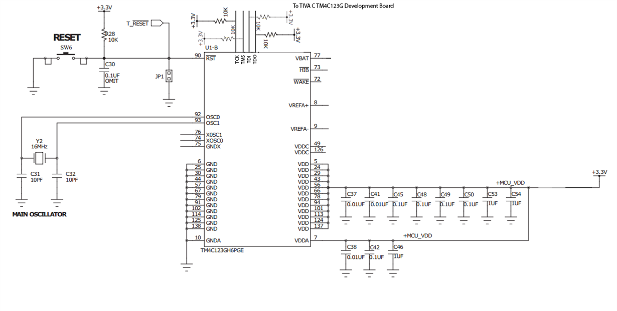
    Thanks for your response. I am attaching schematics of the circuit, please let me know if you think i have made some error in that.

  • Hello Ashish,

    Quite a few mistakes (and serious ones)

    1. The VDDC pins needs decap in the range of 2.5-4.7uF which is clearly missing
    2. If the XOSC pins are not being used then it is advised to connect XOSC0 to GND
    3. The OSC1 pin to Cap needs a Series Resistance (please see data sheet, electrical chapter on MOSC)
    4. Please also look at the System Design Guideline document on HIB and WAKE pins (though not an issue for the current problem)

    Regards
    Amit
  • Hello Amit,

    Yes you are right. Actually this is the circuit given in the board documentation and We did read the whole document and datasheet. But I will elaborate on the issues happening point-wise

    Point 1: When we connect Decap on VDDC its voltage rises from 1.2 to 1.5 and LMFlash utility starts giving error Unable to connect to target - 0!
    Point 2: Ground XOSC - we did the ground but without any success
    Point 3: Series Resistance is mentioned in the MOSC but not present on the Board design neither present on the board
    Point 4: HIB needs to be floating and WAKE needs to be grounded - we have grounded the WAKE PIN

    But now as you have re pointed these issues which could be the cause. I am making corrections to the circuit and will post you the outcome of it.

    Thanks,
    Ashish
  • Hello Ashish,

    Points-1 and 3 are the one's that will have the most serious impact. We have made numerous LaunchPad and customers have field deployed TM4C123 with VDDC decap's and no device rises to 1.5V. You may want to check if there is a strong current source in the vicinity.

    Regards
    Amit
  • Hello Amit,

    Point #1

    Now as per your recommendation I have install 2.7uF on VDDC and shorted PIN 49 & 126 

    The voltage is now within limit 1.2 V

    Point #2

    Grounded XOSC0 and GNDX

    Point #3

    Installed 500Ohm resistance on the crystal

    Point #5 

    left HIB open and grounded WAKE pin as given in the datasheet

    Apart from this I also tried using the internal OSC as the main OSC but that also yielded the same result.

    But still the same error persist. Infact while doing each point I was checking the status and it was similar in all the cases.

    It is possible for you to share some minimum circuit schematics that can be used for programming ? I can make that and try

    Thanks,

    Ashish

  • Hello Ashish,

    You can refer to the EK-TM4C123 LaunchPad Schematic. Also from a debug almost a year back: Have you mounted the Main Oscillator Crystal?

    Regards
    Amit
  • Hello Amit,

    Check out the pic, you will understand that after lots of headache I removed the processor from the development board and took all the connections directly from it so that their is no issue of wrong part. Also I verified that the connections are fine.

  • Hello Ashish,

    Crystal tapped from the DK-TM4C123 all the way to the custom board in the wire-mess. My feedback: I would not even dare try this (I did twice and failed once for 1" of wire). My suggestion: Please remove the wire. GND the OSC0 pin and then try the connect to your custom board to isolate the issue.

    Regards
    Amit
  • Dear Amit,

    Firstly I would like to thank you for your support & patience. We were finally able to make it work.

    Steps that we took to make it work :

    As pointed out by you large wire connections were the real problem in the circuit.

    The major problem was the VDDA pin which needed to be very close to the decap capacitors. We almost soldered it to the pins.

    The other problem was the crystal - as told by you that we needed to keep it close and not too much of wire length. We again soldered it to the pins itself.

    Lastly we soldered the decoupling caps of the power on the power pins and it started working flawlessly.

    Thanks,

    Ashish

  • Did this ever get resolved?
    I have same issue with TM4C129ENCPDT
    I can definitely program the user registers.
    I can issue erase command but the automatic blank check fails, do a manual blank check and this passes.
    Try to program and it fails but then blank check fails so something has attempted to program.
    I have to drop the JTAG and clock to 50kHz to get this much to work.

    User register reading and programming works at much higher speeds (1MHz +).
    I have the latest drivers as far as I can tell 2.09270.0 and latest LMFlash programmer 1613

    Pull ups on JTAG make no difference.
    CCSV6 programs the processor absolutely fine, with or without additional pull ups (100k & 10K tried)?
  • Hello Barry,

    Yes, it did. The last post from Ashish mentions all the issues that had to be resolved to get it to work.

    Regards
    Amit