This thread has been locked.

If you have a related question, please click the "Ask a related question" button in the top right corner. The newly created question will be automatically linked to this question.

CAN bus not working

Other Parts Discussed in Thread: TM4C123GH6PM, SN65HVD1050, SN65LBC184, MSP430F2122, HDC1000

Dear E2E,

I have a problem with CAN module on Tiva C microcontroller, I’m using the following configuration:

1)  Using TM4C123GH6PM microcontroller with both CAN0 and CAN1 connected to two CAN transceivers sn65hvd1050

2)  Since I don’t have CAN cable I’m using 1 meter pair from a CAT6 cable and replaced the 120 ohm resistor with 100 ohm to match the cable

3)  The board is based on my design however the CAN section of the board is based on the TM4C123G Kit from TI

4)  I’m using the CAN example for the TM4C123G Kit after doing the required modifications to work with my processor TM4C123GH6PM

5)  My target is to be able to send CAN messages from either modules (CAN0 and CAN1) to the other as a first step for further development

I used the following code to setup CAN0:

SysCtlPeripheralEnable(SYSCTL_PERIPH_GPIOF);

HWREG(GPIO_PORTF_BASE + GPIO_O_LOCK) = GPIO_LOCK_KEY; // to unlock port PF0

HWREG(GPIO_PORTF_BASE + GPIO_O_CR) |= 0x01;

HWREG(GPIO_PORTF_BASE + GPIO_O_LOCK) = 0;

GPIOPinConfigure(GPIO_PF0_CAN0RX);

   GPIOPinConfigure(GPIO_PF3_CAN0TX);

   GPIOPinTypeCAN(GPIO_PORTF_BASE, GPIO_PIN_0 | GPIO_PIN_3);

   SysCtlPeripheralDisable(SYSCTL_PERIPH_CAN0);

   SysCtlPeripheralReset(SYSCTL_PERIPH_CAN0);

   SysCtlPeripheralEnable(SYSCTL_PERIPH_CAN0);

   CANInit(CAN0_BASE);

   CANBitTimingSet(CAN0_BASE, &CANBitClk);

   //CANBitRateSet(CAN0_BASE, SysCtlClockGet(), 50000);

   CANIntEnable(CAN0_BASE, CAN_INT_MASTER | CAN_INT_ERROR | CAN_INT_STATUS);

   // Enable the CAN interrupt on the processor (NVIC).

   IntEnable(INT_CAN0);

   CANEnable(CAN0_BASE);

I used the following code to setup CAN1:

SysCtlPeripheralEnable(SYSCTL_PERIPH_GPIOA);

   GPIOPinConfigure(GPIO_PA0_CAN1RX);

   GPIOPinConfigure(GPIO_PA1_CAN1TX);

   GPIOPinTypeCAN(GPIO_PORTA_BASE, GPIO_PIN_0 | GPIO_PIN_1);

   SysCtlPeripheralDisable(SYSCTL_PERIPH_CAN1);

   SysCtlPeripheralReset(SYSCTL_PERIPH_CAN1);

   SysCtlPeripheralEnable(SYSCTL_PERIPH_CAN1);

   CANInit(CAN1_BASE);

   CANBitTimingSet(CAN1_BASE, &CANBitClk);

   //CANBitRateSet(CAN1_BASE, SysCtlClockGet(), 50000);

   CANIntEnable(CAN1_BASE, CAN_INT_MASTER | CAN_INT_ERROR | CAN_INT_STATUS);

   // Enable the CAN interrupt on the processor (NVIC).

   IntEnable(INT_CAN1);

   CANEnable(CAN1_BASE);


My problem is:

I never got a correct communication I always get the error reg “ui32Status” with a value of 0x000000E5

I did several trials to solve this error but none of them worked, I don’t know what shall I do or how can I get a better understanding of the problem to solve it.


Any support is highly appreciated.

Mina.

  • Hello Mina,

    Simplify. If you connect the CANH of the transceivers and CANL of the transceivers with the same termination does the issue still come. Why!!! because the cable may itself be the big if.

    Also why is the CANBitRateSet been commented. I would suggest a low CAN bit rate before changing the timing values just as in the examples

    Regards
    Amit
  • Hello Amit,
    Thank you for your response,
    Regarding the connection: yes I’m connecting both CANH and CANL of the two transceivers via a CAT6 cable pair of length of 1 meter.
    Regarding the “CANBitRateSet” I was using it with the following:
    1) With bit rate of 500000 error code: “ui32Status = 0x000000E5” (what does it mean?)
    2) I decreased the bit rate to 50000 same error codes.
    3) Changed to CANBitTimingSet  same error code.
    4) Disconnect the cable  same error code.
    5) Trying to remove termination resistor from either sides or both sides  same error code.
    I checked the hardware connection to check the following:
    Tx and Rx are connected properly to the microcontroller pins for both transceivers.
    CANH and CANL are connected properly to the terminal block pins for both transceivers.
    Both CAN transceivers are properly powered by 5V
    “S” signal pin is connected to ground
    Vref left open
    Cable has no internal cut; both CANH and CANL for the two transceivers are physically connected and measured.
    I have a previous experience with CAN as I did it in a product year 2006 with PIC18F458 and MCP2551 from microchip it was working on CAT5e cables, I was putting 3 nodes on a cable of total length of 620 meter (both ends and middle), changed the termination resistor from 120 ohm to 100 ohm and the system was working fine so the cable itself is tested on less quality / less performance hardware.

    So that all sounds good but this time the system is not working. The board I’m testing on now is huge, it contains the following:
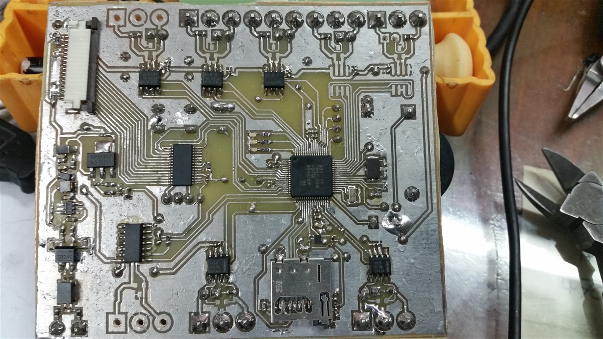
    Tiva C MC, 5 x sn65lbc184 RS485, 1 x buffered UART (7407), 2 x CAN, 2 x sn65hvd1050, 1 x HDC1000 sensor, 1x SD card connector, 1 x MSP430F2122 to drive alphanumeric LCD and read some press buttons and communicate with the Tivc C microcontroller via UART, power management circuit with good EMI protection.
    Most of the board functions are working so far except what I didn’t develop yet (SD card and RS485).
    So I have the confidence that my board is well designed, and I’m using new components so the components also is ok, the problem is I did all what I can to just know where is my error or mistake and I failed so I need your support please to find out the problem and fix it.
    Thank you for your support and understanding.
    Best regards,
    Mina
  • Hello Mina

    The Error Status of 0xE5: Bus Off, error passive state for continuous more than 127 errored frames and bit-0 error where instead of 0, the line is detected as 1.

    I do not have your board schematic nor the full view of the code. What I may suggest is to see when CAN controller is sending the data, then does it receive the same on the CANRX pin with and w/o the cable connected, to see if the Transceiver is working.

    Regards
    Amit
  • Hello Amit,

    Thank you, you made it in less than 24 hours, thank you again.

    You pointed to the transceivers, although I was sure they are properly configured and powered, and checked it before, I found great mistake, shame on me, I mixed up the CAN Tx and CAN Rx so it was normal that nothing works.

    I corrected the board (by cutting the wrong tracks and reconnect them again properly) and tested the code with the following results:

    1)      First trial failed

    2)      Changed the “CANBitTimingSet” to “CANBitRateSet” with bit rate of 50K à it worked

    3)      Updated the bit rate to 500K à still working

    4)      Some few times I found the following error:

    1. “ui32Status = 0x0000ABAA” (what does it mean?)
    2. The code reset it to “ui32Status = 0x0000AB00” and trigger a false data reception
    3. I tried to clear it manually to “ui32Status = 0x00000000”
    4. It happens again and again until I soft reset the microcontroller

    So please advise me the following:

    1)      What is the meaning of “ui32Status = 0x0000ABAA”

    2)      Where can I get some information about the error flags, the “CANSTS” register includes only 7 error types plus one normal stat, the can.h file found in “C:\ti\TivaWare_C_Series-2.1.0.12573\driverlib” doesn’t give enough information and I was not able to get a meaning for bits 8 through 15 (AB) in the “TivaWare Peripheral Driver Library”.

    3)      If that error happens again how can I handle it without the need to reset the microcontroller.


    Thank you very much for your support and understanding.

    PS: I’m attaching the photos of the prototype board that I’m doing my development, it was printed and soldered in my lab.


    Best regards,

    Mina

  • Hello Mina,

    1. The CANSTS register is 8-bit so a code of 0xABAA is something I haven't seen or I don't think that is possible.
    2. The CANSTS register bits are explained in the CAN Section of the Data sheet.
    3. Every error has a meaning and needs to be handled differently. As an e.g. a BUSOFF error requires that the bus be powered up. An error where the bit is read as 0 instead of 1 would mean a bus collision and requires back-off and re-try.

    Also the manual wiring of the Transceiver, due to criss-cross of TX and RX to the CAN transceiver may be a source of error. So I would suggest a careful re-route if possible.

    Regards
    Amit
  • Hello Amit,
    I took me some time to read more about the CAN and to test more, and here is my comments:
    1. Regarding the error 0xABAA, I completely agree with you, logically it is impossible to happen, even the code handles the first 8 bits only however that was what I'm getting in the debugger so I’m really confused, but the good thing is that the error didn’t appear again since my last post.
    2. I’m checking the datasheet, thank you
    3. Regarding the error handling, I suppose that most errors will happen during development and once fixed then I’ll work fine, please correct me if I’m wrong, (and if possible support me by some examples).
    I’m building another proper board but I’ll print it once I make everything on this board work.

    I have another problem in the SD card, again I’m following the schematic found in the EK-TM4C123G kit, I double checked it this time well and I’m including the SD card example for the kit “EK-TM4C123G” but during the including I got lost as I don’t have a UART terminal connected to computer in this board also my target is to create .txt file and save it in the SD card (as Log files) and read some txt files from SD card (as configurations, modes or settings) so I searched a bit in the internet I used the example found in http://elm-chan.org/fsw/ff/en/open.html but I was surprised that the “f_mount” command has more parameters than the one in the included file system.
    So I’m really lost, please guide me how to achieve my target?
    Thank you for your powerful support
    Best regards,
    Mina
  • Mina Anton said:
    So I’m really lost, please guide me how to achieve my target?

    And - so too will be all others - who have no idea that your, (Original Subject) "CAN Bus not working" has suddenly veered into an entirely different subject/topic area!

    That's not good - Amit's work here is intended to assist/guide many - not a (lost) few!

    Methinks a new post - cleverly titled, "SD card not working" (sic) would far better serve you and the broad forum community...  (and would achieve the "powerful support" you memorialize...)

  • Hello cb1_mobile ,

    you're 100% correct, it seems that I'm really lost :-) and writing in the wrong place, I'll start a new topic with your suggested subject willing that both of Amit and you check it.

    Best regards,
    Mina
  • Hello Mina
    Glad to help you out on the new post...
    Regards
    Amit