This thread has been locked.

If you have a related question, please click the "Ask a related question" button in the top right corner. The newly created question will be automatically linked to this question.

I want to download firmware, But I get an error message 'Flash Timeout. Reset the Target and try it again.'.

Other Parts Discussed in Thread: TM4C1230C3PM

Dear. TI Support Team.

Hi, Last week i bought the TM4C1230C3PM Chip. and i connected ULINK2 JTAG to download firmware in Keil uVision 4.73.

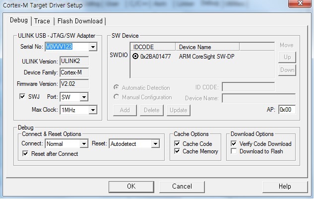
As you can see, I can see that JTAG & Chip are working in Keil uVision. Therefore, between chip and JTAG connect correctly.


But When I try to click 'download button', I can see  'Flash Timeout. Reset the Target and try it again.' message.

and Flash download failed. I have never downloaded firmware successfully.

I don't know why that happend.

Please Can you explain why it is?

Best regards. Have a Good Day.

From Jeon.

  • Hello Jeon,

    I believe it is a custom board that you have? Can you please refer to the following post for initial self-diagnosis?

    http://e2e.ti.com/support/microcontrollers/tiva_arm/f/908/t/374640

    Regards
    Amit
  • Hello Amit,

    Thank you for your reply.

    Yes, I have a custom board.

    Previously, i wish to resolve my problem, so i read this web page you say.

    As you know, this web-page doesn't have information about 'Flash Timeout'.

    I'm eager for solving my problem.

    Have a Good Day :)

    Best regards

    Jeon

  • Hello Jeon,

    A flash timeout may mean that JTAG is not connecting to the device correctly. That is why the steps mentioned in the post are as a checklist to ensure the end user can check if none of them are true and then post.

    Regards
    Amit
  • Hello Amit,

    Thank you for your reply.

    I heeded your advice and checked my board through check of list.

    Please look below.

    1. Main Oscillator is mounted and soldered down well.
    - Yes, I connected Crystal(12MHz) & Capacitor(10p) to OSC0 Pin, and OSC1 pin too.

    2. If not using Main Oscillator then ensure OSC0 pin is connected to GND
    - My board was connected Crystal & Capacitor.

    3. The Decap on VDDC should be in the range of 2.2uF to 4.7uF
    - I didn't connect Capacitor between VDDC and GND.

    Is this capacitor the crucial factor in firmware downloading enviroment?

    I just think that it is only capacitor to reduce noise.

    4. The RST_N Pin is Pulled High to VDD Supply

    - Yes, In my board, RST Pin is pulled High to VDD.

    5. The JTAG Has Pull Up's as well (this is always a good to have in case of custom board layout)

    - Yes, TMS Pin use 100K Ohm pull-up resistor to VCC. and TCLK Use 100K Ohm pull-up resistor to VCC.

    6. If the device is a TM4C129 with Ethernet PHY and there is a 25MHz crystal, then check if a RBIAS pin is connected to GND via a 4.89K resistor.

    - Now, I am using TM4C123.

    I ask you for good advice.

    Best regards

    Jeon
  • Hello Jeon

    The VDDC Cap is a "must". Due to dip in core voltage when the debugger is connected the "noise" can cause the VDDC to drop and trigger the reset breaking the debugger. Also the caps need to be as close as possible to the VDDC pin. Please refer to the System Design Guidelines for TM4C123 for placement of the cap.

    Regards
    Amit
  • Hello Amit,

    Thank you for your reply.

    Thanks to you, I can discover new fact about VDDC capacitor.

    I will try to connect Capacitor between VDDC and GND.

    After this work, I will say the result to you.

    Have a good day :)

    Best regards

    Jeon
  • Dear Amit,

    I want to express deep gratitude for your advice.

    The cause of downloading failure is non-existent capacitor.

    After using the Capacitor(3.3uF), My board works well.


    Have a Good Day.

    Best regards

    Jeon