This thread has been locked.

If you have a related question, please click the "Ask a related question" button in the top right corner. The newly created question will be automatically linked to this question.

Peripheral Problems XM4C129

Other Parts Discussed in Thread: TM4C129XNCZAD

Hello,

currently, I am developing a firmware for the XM4C129 controller from you. Now, I have a problem with some peripherals, especially the PWM0 and GPIOH.

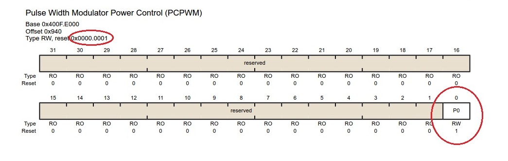
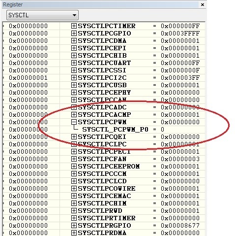
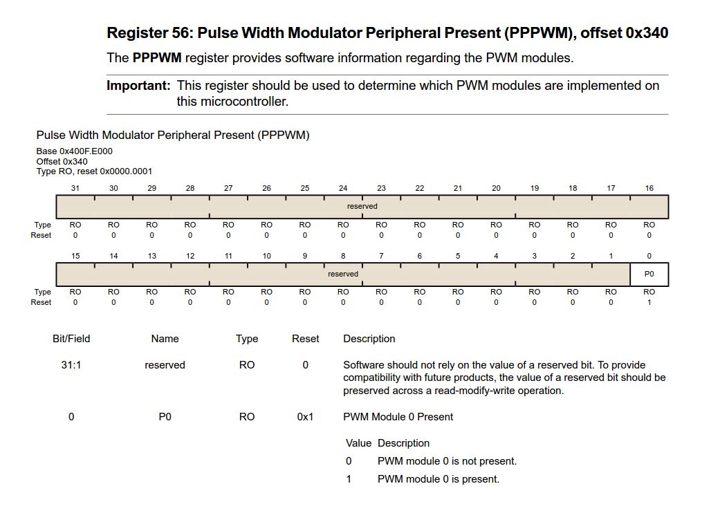
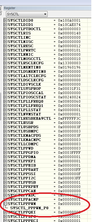
During initializing the PWM0 module I want to set the prescaler of the clock register. I call the function PWMClockSet() of your delivered library to set the prescaler. In this function there is a read access for the given register (HWREG(ui32Base + PWM_O_CC)). If my program calls this routine, then the program jumps to an undefined address. After a while it jumps into an exception handler. I tried to check the peripheral settings with my debugger, but in the IAR workbench I got no access to the peripheral / memory. It makes the apparent that this peripheral is not implemented in the controller.

I have the same problem with the GPIOH peripheral. If the firmware tries to read from the register, the firmware jumps to an undefined address. During debugging I have the same problem with no memory access to this peripheral.


Is it possible that this controller have a problem? Are there some peripherals not implemented? Do you have some restrictions using this controller?

Here are my both controllers which I am using:

Best regards

Tobias

  • Hello Tobias

    Can you share the code? It seems that for the CPU to fault like this the Peripheral has not been enabled or if it is enabled then a delay or peripheral ready check has not been done before accessing it. The simplest thing to do is to check if the RCGCPWM and RCGCGPIO for the peripheral instance are set via the debugger

    Regards
    Amit
  • Hello Amit,


    on the controller with the production date 3C (see the pictures above) the PWM0 peripheral is working. Then I tried the same code on the controller with the production date 3B. There it is not working. So, my assumption was that the peripheral is not implemented in the controller.

    Regards

    Tobias

  • Hello Tobias

    The devices are identical in terms of revision so the PWM0 and GPIOH should be there. The production date does not make a difference. Can you check the registers as mentioned above and the registers PPGPIO and PPPWM and send the data

    Regards
    Amit
  • Tobias Langenbacher said:
    ...controller with the production date 3B. There it is not working...

    May we ask what (if anything) works w/in that "3B" dated controller?  The conclusion that multiple peripheral blocks are somehow "missing" is (of course) mistaken!  (one wonders - what happened to schools' past teaching, "Always blame yourself first - the device last!")  Over the decades - that guidance shines supreme...

    We use multiple seats of paid IAR - have never noted the absence of peripheral. As Amit has noted - are you sure that you've properly enabled?  (although your report of one board working much counters a set-up/config error)   

    Again - what works?  Do all other ports come up & perform - first under GPIO Output test/verify?  Never - in more than 10 years w/ARM (many vendors) have we seen a "dead/awol" specified peripheral!   If yours is a custom board - we'd hazard the guess that you've not fully powered each/every MCU power pin - to include those requiring tightly spec'ed capacitors to realize their (internal) charge pump.

    Assume yours is KS IAR - have you upgraded to latest/greatest version?  And - if so - have you properly spec'ed that "129" as the DUT?  (device under test)

  • Just 1 note to cb1... bad grades? not working? Blame the teacher not my son - it's very common now.

    @Tobias
    If you could provide the code it would be most helpful, i think you understand.
    Could you please check the registers in the debugger as Amit suggested.

    You seem to want the problem to be with the controller. But it might be the code or even the board (that give much more work for you than the 1st option).
    Can i suggest something easier for now? Erase the entire flash of the "3B" with the "LM Flash Programmer" software and then program it again. Second if that doesn't work- check the code or paste here so we can help. Third and most painful - check the board (if you could do that in second it would be best as it's most likely since the code worked in "3C")
  • Luis Afonso said:
    Blame the teacher not my son...

    But - No "son" was blamed - my young friend.   Might your "read" have been a little too fast/furious - thus you missed/misunderstood! My quote, "What happened to schools' past teaching?" does not focus "blame" (exclusively) on any one party - but instead - highlights the weakness of, "blaming the IC!  

    In my 7-8 years here (forum) - never can I recall the MCU's being "blamed" for awol peripheral!  Poster may (instead) look more closely @ "man in the mirror" - (usually) a more fertile "target" for blame...

  • Hello All,

    In all fairness, let's get the data from Tobias.

    Hello Tobias,

    Also are you running the same application image on both the devices? What really interests me is the XM4C129XNCZADI2 marking on the device as these were never production devices.

    Regards
    Amit
  • Amit Ashara said:
    In all fairness, let's get the data from Tobias.

    Do you mean like (posted earlier) "Again - what works?  Do all other ports come up & perform - first under GPIO Output test/verify?"

    By my read - it's most valuable to learn "if and which other peripherals" perform - that MCU.

    As for the "XM4C" marking - we've shipped over 2K boards w/LX4F marking - those devices never made it to LM4F status...

  • Hello cb1,

    Yes and the PP-RCGC settings.

    Regards
    Amit
  • Hello,

    I think I have found a reason why the PWM0 peripheral is not working on the 3B-controller. The System Control Register "Pulse Width Modulator Power Control (PCPWM)" is specified in the datasheet (TM4C129XNCZAD Rev. June 18, 2014) with a reset value of 0x0000.0001. But in my 3B-controller the reset value is 0x0000.0000, see picture of the debug interface. So the power of the PWM0 is disabled. I tried to set the bit in the register, but it didn’t worked. Maybe there is a protection.

    In the 3C-controller the reset value is 0x0000.0001.

    This is my function to initialize the PWM0. The called functions are from the Tiva Peripheral Driver Library of TI.

    void factorySelftest::initPWM () const
    {
       /* Configure PWM module and Pin */
       SysCtlPeripheralEnable(SYSCTL_PERIPH_PWM0);
       SysCtlPeripheralEnable(SYSCTL_PERIPH_GPIOR);
       PWMClockSet(PWM0_BASE, MG_PRESCALER);
       GPIOPinConfigure(GPIO_PR4_M0PWM4);
       GPIOPinTypePWM(GPIO_PORTR_BASE, GPIO_PIN_4);
       PWMGenConfigure(PWM0_BASE, PWM_GEN_2, PWM_GEN_MODE_DOWN |
          PWM_GEN_MODE_NO_SYNC);
       PWMOutputState(PWM0_BASE, PWM_OUT_4_BIT, TRUE);
    }


    The same code is working on the 3C-controller without problems. The PWM0 is enabled and works fine. On the 3B-controller during initializing it ends in an exception handler.

    My main problem at the moment is the PWM0. The GPIO register was just a test. With that I tried to reproduce the same problem like the PWM0 with write acces to the memory.

    regards,

    Tobias

  • @cb1_mobile:

    I am aware that the problem might be in my code. But from my point of view it is a little bit unusual that the same firmware is working fine on the 3C-controller and on the 3B-controller it has problems.

    The mark of the controller as “XM4C” means that it is an experimental device and it can have some failures, see picture. So, I do not rule out some controller failures.

  • Hello,

    I have found further informations, the 3B-controller do not have a PWM0 module. The system control register 56 "Pulse Width Modulator Peripheral Present (PPPWM)" is specified as follows:

    The register in the 3B-controller has the value 0, see the following register picture. The register value in the 3C-controller is set to 1. So the 3C-controller has a PWM0 and the 3B-controller not.

    Regards

    Tobias

  • Hi,

    Try adding SystemCtlDelay(3); after enabling both clocks and before you do anything else.

    I belive the problem is that you are not waiting the miinimum 3 cycles before accessing a peripheral registers before enabling them. In the previous version the clock was enabled by edfault do that problem didnt happen

  • Luis Afonso said:
    ust 1 note to cb1... bad grades? not working? Blame the teacher not my son - it's very common now.

     Hi Luis, forever as Teacher I have to ABSOLUTELY discourage this!!

     We have bad sons as bad teacher, your phrase is highly biased toward teacher as is common now, is this correct? Yes and generally NO!!!

     Luis I see from your site you enjoy a some alternate teaching form; don't seem this same of blaming yourself??

     So take care about this free talking, we own a huge lot of bad pupils and these are screaming everywhere had "bad teacher" parent sustained when first is absolute lack of basic knowledge and absolute lack of skill needed to perform simple algebra, so they search for someone solving his job for free. This is also the deepest lack of education on all the sense of word both sides!!

     Take great care about this and remember I blame my pupils when they attack a colleague also if this one is known as bad and leaving this generation grow this way your son forever get a WORST teacher got from these.

     My phrase generally approach this:

     <<<What I can think you speak about me to my colleague when you do this in front of me? Are you sure of this or you are just "not prepared to lesson"?>>>

     Bad teacher exists but it is not just pupils voice to be selection of skill they don't have so cannot evaluate too.

     Think a lot about word sense before to fire or hire.

  • Tobias Langenbacher said:

    I am aware that the problem might be in my code. But from my point of view it is a little bit unusual that the same firmware is working fine on the 3C-controller and on the 3B-controller it has problems.

    The mark of the controller as “XM4C” means that it is an experimental device and it can have some failures, see picture. So, I do not rule out some controller failures.

     Hi Tobias, WE know about nomenclature and also experimental silicon, all our initial development was on XM and also on LX Stellaris (Xperimental before to get LM aka Luminary Micro Stellaris) before ws renamed to TIVA...

     Finally some sort of MUST have information got to light, so you need get help and HELP OTHER to try analyse your problem with data and not free word as "it doesn't work" so what is not working???

     Edit: May be also timing changed due to silicon releases and what it was at limit on one is no more respected on successive release, to avoid this DATA SHEET recommendation about minimum time or cycles has to be respected.

      Last question, why you still are using XM limited to sampling when TM GA silicon is in production?

  • Hello Tobias

    Clearly with the PPPWM bit 0 the PWM-0 module is not usable. However the GPIO H should still be usable as the PPGPIO for Port H is set to 1.

    Also since the device carries the XM4C marking it may not have been set to the right setting. I would suggest replacing the XM4C with the production qual-ed TM4C devices and sending the XM4C part back to TI for Fail Analysis (you may send it back to the distributor which would be returned back to us)

    Regards
    Amit
  • Hello Roberto,

    I have explained my problem in the first post.

    Roberto Romano said:
    Hi Tobias, WE know about nomenclature and also experimental silicon, all our initial development was on XM and also on LX Stellaris (Xperimental before to get LM aka Luminary Micro Stellaris) before ws renamed to TIVA...

    My company got the hardware from our customer, so we didn't had influence of the controller selection. Now, I can report  our customer the problem of the XM controller and so they have to change it to TM.

    Tobias

  • Hello Amit,

    thanks for your response.
    I do not use the GPIOH register, it was just a test to reproduce the same failure like the PWM0.

    Regards
    Tobias
  • Your analysis was very good. The information is very interesting. You helped me so much.
  • Tobias Langenbacher said:
    My company got the hardware from our customer, so we didn't had influence of the controller selection. Now, I can report  our customer the problem of the XM controller and so they have to change it to TM.

     I read that but if you read again my question was why still use an old silicon when GA TM is on production.

     I bet CB1and Amit  too, so <WE> suggest to test firmware on last silicon release ASAP before to start mass production, sample seems more close to final production and a fine pitch PCB cost a lot, as Amit suggested ask for a replacement then try with GA to be sure of nowaday production,.

     XM suffered a lot of problem not only this but also ENET module was hiccup, you can find a lot of post about this trouble and most of them was when I got DK on debug mode to try run my code it.

     Edit: I reread first post and say you are developing the firmware for this processor, this seems production ready but launch to market  maybe in future if this is not a workaround, if WA it is not specified too,  if you are doing this now has sense to use old silicon you cannot buy for production or it is better use latest version?

     My code was developed on XM silicon but now I am testing on latest LM I got few day ago, XM was got about one year ago and just few pieces are available as old stock evaluation samples at an higher price. See Mouser, Digikey and other distributor.

  •  Hi Tobias, to be clean and clear about I readed back again all posts on this thread and :

    Tobias Langenbacher said:
    I have explained my problem in the first post

     Just Said you are developing firmware on two chip of TI firm and one oldest early Internal alpha sample doesn't work.

     Did you read silicon errata? [not written]

     Did you read first sticky post on forum like the one Amit suggested driven by Fault ISR?

    Tobias Langenbacher said:
    My company got the hardware from our customer, so we didn't had influence of the controller selection. Now, I can report  our customer the problem of the XM controller and so they have to change it to TM.

     And this appear on this last sentence only, so when you post something to ask for help check how to do, this is reported on sticky, at last your problem was real and related to very early silicon with very few samples produced so it was also incomplete.. Again Silicon errata?

     Happy to have you in this forum but we still need identify beginner level behaving as professional and we meet too many I forever ask for a discipline to this tools otherwise real professional don't like use it.

  • Hi roberto,

    Roberto Romano said:
    Hi Luis, forever as Teacher I have to ABSOLUTELY discourage this!!

    I've spoken of what i see more and more in patents meetings. Which most of the time i found ridiculous, i had the luck of mostly having good teachers. I dunno, maybe the students were hopping to coarse the teacher to big better grades by convincing the parents they were bad teachers.

    I agree ot course there are good and bad teachers but i hate when parentsband students blame good teachers for their own lack of work.