This thread has been locked.

If you have a related question, please click the "Ask a related question" button in the top right corner. The newly created question will be automatically linked to this question.

EK-TM4C1294XL - "Unable to initialize the target"

Other Parts Discussed in Thread: EK-TM4C1294XL, LM317

Hello everyone, I've encounter a problem with my EK-TM4C1294XL evaluation kit.

At the time when problem arose, Tiva was connected to external power supply (3.3v) over booster pack 1, and had Adafruit CC3000 attached to it. 3.3V power supply was derived from 220V AC to 12V DC external adapter and then adjusted to 3.3V with LM317 circuit. Software inside was modified cc3000 example from TivaWare from basic Web Client app, and it was already running for a few days with no observed problems at all. At one point I've noticed all user LEDs turning off, leaving only the power LED on and the program on board didn't work any more. I tried uploading a program with CCS (v6) but getting error message:

"Error connecting to the target:
Frequency is out of range."

I tried using LM Flash Programmer (Build 1606), to update ICDI firmware(which seemed to give no error message) and the device was recognized in Device manager with assigned COM port. Also tried performing debug port unlock (no error messages on '...TM4C192 class' option, but problem was still present), but when I try to erase flash or do a blank check I get an error message saying:

"**ERROR**: Unable to initialize the target -0!" or

"**ERROR**: Unable to initialize the target -1!" when I try to do unlock debug port on 'Tempest and Firestorm Classes' option

I realize that the board is most probably fried, but before I throw it away I just wanted to check if anyone has any ideas/suggestions?

Thank you for your time :)

  • Hi Vedran,

       When you performed the Debug Port Unlock, did you remove the Adafruit CC3000?

       Anyway if the Adafruit CC3000 is still connected to Tiva Connected Launchpad, remove it then perform Debug Port Unlock.

    - kel

  • Hi Markel,

    Yes, I did.

    Is it possible that the problem occurred because I forgot to change jumper JP1, used to select the power source. I think I left it on 'ICDI' even though I was using external PS from Booster pack?

  • Vedran Mikov said:
    Is it possible that the problem occurred because I forgot to change jumper JP1, used to select the power source. I think I left it on 'ICDI' even though I was using external PS from Booster pack?

    I have not done that before with my Tiva Connected Launchpad, so I don't know what will happen. Much better if a TI Engineer reply regarding this.

    If you return your Tiva Connected Launchpad to its original configuration and still not able to recover it using LM Flash Programmer tools, then there might be a problem with your Tiva Connected Launchpad.

    - kel

  • Markel Robregado said:
    If you return your Tiva Connected Launchpad to its original configuration and still not able to recover it using LM Flash Programmer tools, then there might be a problem with your Tiva Connected Launchpad.

    Do you mean disconnecting everything and placing all the jumpers to default state? If so, I tried, nothing happened.

    Thanks for your help so far :)

  • Vedran Mikov said:
    At one point I've noticed all user LEDs turning off, leaving only the power LED on

    Does not that sentence provide a strong clue as to what (likely) happened - and how you may "fix" your board?

    Almost certainly those user Leds connect to 3V3 or 5V (thru current limit R) and then onto MCU for individual control.  It's also possible that the MCU sources current - and those Leds each tie one lead to circuit ground.  (that instance will complicate your troubleshooting - sorry about that)

    If those Leds connect to 3V3/5V and they're all out now - such may signal the "loss" of that 3V3/5V.  And - working with your board schematic - you should be able to trace backwards from those (common) Led tie-points to the board's power source.  At some point that 3V3/5V has likely been lost.

    Another clear clue is your honest (good for you) admission that you had the power routing switch in the improper position.  I'd bet that was the fundamental cause of your problem - and that you may be able to correct it.  Now I've (not) your board - nor have I searched for schematic - but it's (again) likely that with that power routing switch set incorrectly - AND if the USB cable was connected while you supplied external power - you suffered, "power contention" and one (or several) of your power routing/regulation components was harmed. (due to excessive power dissipation)

    Now - if you're lucky - that damage may be confined to a single device - and repairable.  Your job is to work backwards - as stated I'd start w/those Leds - and see "if and where" they lose their connection to the voltage source.  If this proves too complex you may ask someone local to you for assistance - or wait for vendor to (maybe) arrive - and (surely) others here have done similar (bad power switch placement) and vendor's (internal) troubleshooting guide should reveal the "how/why" of such repair.

    Good luck - in any case - way too soon to "toss" that board - do some work - have faith...

  • cb1_mobile said:

    If those Leds connect to 3V3/5V and they're all out now...


    One important thing I forgot to mention, but thought it's kind of implied: other than user LEDs turning off(they were used to provide feedback on CC3000 WiFi module, like 'connected to network', 'socket opened' etc.), and being unable to upload anything to board, the program on the board itself was not executed any more.

    Thanks for the power tip, I'll start checking the voltage around the board!

  • Vedran Mikov said:
    I forgot to mention... kind of implied: other than user LEDs turning off... they provide feedback...

    Kind of implied may not provide, "best/brightest" diagnosis from those remote - and w/out your board - nor full knowledge of its multiple interconnects.

    From what you report - it may even be possible that you've lost power (3V3) to the MCU - and with luck that may not prove fatal.  The fact that your board still "fails" when (isolated) from all interconnected others - points to a good chance of power loss @ one (or more) of the power distribution and/or regulation blocks.

    Suggest that you print a copy of board schematic - and then systematically probe from each power inlet to regulated output(s).  It may prove safest to simply "ohm out" the various 3V3 paths - seeing if any read close (now) to ground - or God forbid - close to 5V!  (this saves potential (further) damage to your board - which may occur while under improper power)  You may "red-line" the schematic as each point/component is checked - preventing your duplication of effort...

    From years in the trenches - likely suspect is the USB 3V3 regulator - which (appears) to have received "reverse power" (3V3 introduced "externally" to its output! - that's never supposed to happen!) via your having the power switch in the improper position.  (bet you'll pay more attention - now - yet we've all done that!)  Further - while these boards claim "launch" - a superior design would (eliminate) that switch - sense the source of power - and automatically route the voltage to prevent your predicament.  (launch indeed - econo-pad may better describe...)

    If indeed that USB 3V3 regulator has died - and you're particularly unfortunate - it may have failed shorted - applying the full USB voltage to the board's 3V3 power rail.  (expect that your MCU said "ouch" - that likely was fatal...)

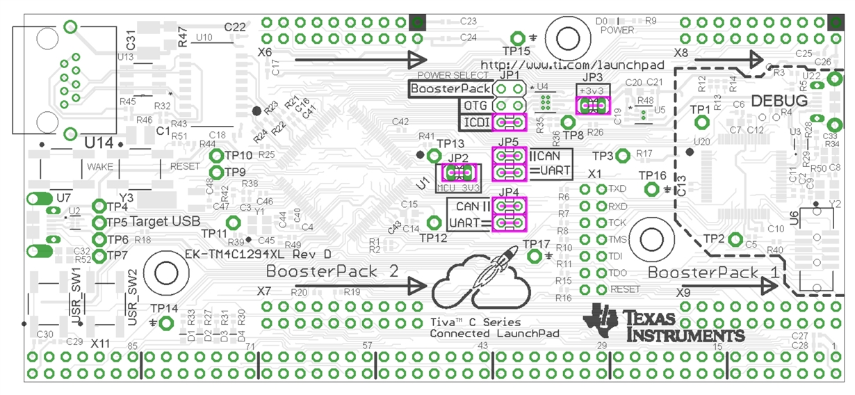
  • For those of you willing to help but don't have the layout, here is a quick look:

    And here's a link to manual with schematics(starting from page 27): http://www.ti.com/lit/ug/spmu365a/spmu365a.pdf

    After poking with probes around the board I observed the following:

    -all 3.3V & 5V outputs are connected together (checked by measuring resistance)

    -all GND outputs are connected to each other (i.e. no connection between ground pins has been cut off)

    -RESET button shows 3.3V on one of the pins (pull-up works fine) when board is powered on

    -WAKE button show however around 1.6V on one of the pins, but I assume it's because of big resistors

    -the power LED turns off in case of short-circuit (no surprise here, but can't find how exactly is connected)

    When JP1 is set so I use ICDI as power source:

      -measuring current on JP2(MCU current) I get 32.5mA right after powering the board, but once I press RESET i drops to ~6.9mA and stays there until I plug off the USB cable(power source) and plug it back in (power up the board again)

      -measuring current on JP3 (MCU & debugger current) I get 55mA once the board is powered on, and 31.2mA once I press RESET button

      -JP1 voltage: ~5V

      JP2, JP3 voltage 3.3V stable

    When JP1 is set to power up the board from OTG, other USB port:

      -current on JP2 is the same, 32.3mA after power-up and  6.8mA after reset

      -current on JP3 is 54.1mA after power-up, and 30.2mA after the button has been pressed

      -JP1 voltage shows ~5V

      -JP2 & JP3 at 3.3V stable

    Switching JP1 to to use source from booster pack, and supplying 3.3V to booster pack:

      -current on JP2 is always 6.8mA (after power-up and pressing RESET)

      -current on JP3 gives 0mA

      -JP1 voltage is however 0V  (??)

      -JP2, JP3 voltages on 3.3V as expected

    Switching JP1 to to use source from booster pack, and supplying 5V to booster pack:

      -current on JP2 is again 32.8mA after power-up and drops to 6.8mA after RESET is being pressed

      -current on JP3 gives 37.8mA after power-up and drops to 30.5mA after RESET is pressed

      -JP1 voltage 0V (??)

      -JP2, JP3 voltages as expected at 3.3V

     -there is a huge voltage drop (from 5V to 3.5V) on the power line I use to supply board, causing all 5V outputs on the board to give 3.5V instead of 5V

    When connected to power supply (any of three tested) no components on the board seem to heat up.

    I'll continue to poke around if I come up with something else, in the meantime I'll probably order new one, I was really satisfied with it.

    Thanks everyone for help so far.

  • Vedran Mikov said:
    all 3.3V & 5V outputs are connected together (checked by measuring resistance)

    One hopes this is a, "language issue" and that 3V3 does not directly connect to 5V0!  Perhaps you can (better) detail.

    The graphic of the board is nowhere near as helpful as your "trace" of the various power distribution/regulation signal paths via a "schematic!"   (as past suggested)


  • Crap, I didn't mean to say they are connected all together, rather all 5V outputs are connected, and all 3.3V outputs are connected together.
    I don't really have more than a multimeter to trace all the signal paths, perhaps you could explain how should I do it?
  • Vedran Mikov said:
    rather all 5V outputs are connected, and all 3.3V outputs are connected together.

    Better - but best would be, "All 3V3 signal lines remain intact & measure correctly - same holds true for all 5V0 signal lines - AND 3V3 & 5V0 are not connected together!  (thank UCLA law for that)

    Multimeter should be ok - you must check that first 5V0 - and then 3V3 route (as per the schematic) to all points revealed therein.  (this is what I meant (earlier) by suggesting that you "red-line" your printed copy of the schematic)

    I still believe yours is a power regulation or distribution issue - caused by the (likely) introduction of 3V3 into an (unpowered) 3V3 regulator's output.  (that is to be avoided - at all costs)

    The 5V0 causing damage is "less likely" due to it's (normal) introduction to the input of one (or more) 3V3 regulators - unless 2 or more 3V3 regulators had their outputs (someway) joined.  (again - such practice is to be avoided)

    I'd still be reluctant to "toss" that board - your full trace of the power/regulator paths & components is likely to prove beneficial to you now & in the future.

    Good luck.

  • I got some time to poke around the board again, so after measuring resistance and ensuring that all 5V outputs are connected together, and 3V3 outputs are connected together I plugged in USB cable to ICDI and started examining voltages, and got the following:

    U4

    1. GND
    2. IN -> measured ~5V
    3. EN1 -> measured ~5V
    4. EN2 -> 0V
    5. OC2 -> 0V
    6. OUT2 -> 0V
    7. OUT1 -> 5V
    8. OC1 -> 5V

    U5

    1. OUT ->3V3
    2. NR/FB -> 1V2
    3. GND
    4. EN -> 5V (also seen on TP3 pin)
    5. NC
    6. IN -> 5V

    Then I examined TM4C123 and got stable 3v3 on VDD pins(2,11,26,42,54), also measured VDDC pin 25 to be1v2.

    Measuring on TM4C1294:

    VDD pins 7,16,26,28,39 show stable 3v3,
    VDDC on TP12 shows 1.18V(according to datasheet within the operating range)
    VREF+ on TP13 shows 3v3
    WAKE on TP10 is 2.959V (due to resistors)  and on TP11 reads 3v3
    HIB on TP9 is 3v3

    I also tried and measured all of the resistors hoping to find that one of the pull-ups blew off, but only thing I could see are R21,R22,R23,R24 being 0 ohms instead of 49,9, but they are used only to pull up ethernet lines. And resistor R26 on power supply(U4) shows 20k instead of 100k (but it can be that there is less resistant path around, that the multimeter measures instead).

    Concluding this, made me think that it's not power problem (maybe there still something I didn't check?) so I thought it might a problem in communication between ICDI and target. I removed resistors used to connect those two (R6,R7,R8,R10,R11,R15,R16) and installed a header on X1. Leaving the header disconnected (meaning there's no connection between ICDI and TM4C1294) I ran LM flash on computer I got the exact same error message as is in title of this topic. Putting jumpers on didn't change anything. I also tried measuring resistance between X1 header and pins PC0 - PC3, PA0, PA1 on TM4C1294 used for debugging interface, everything was connected properly. Last thing I tried was connecting oscilloscope to X1 header; I could see that ICDI is trying something, TP1 pin (signaling Debug Active) went high for the time that I ran LM flash on computer, RXD, TCK, TDI and RESET  line were held high when idle, and TCK, TMS, TDI and TDI seem to do something when I run 'Blank flash check' in LM flash, however, at the same time, TXD(low), RXD(high) and RESET(high)  doesn't seem to change their state.

    I can try and make oscilloscope capture later on, if necessary.

  • Two + weeks time passing forces reread of this whole thread - simpler would be your acquisition of an identical launch pad - and attempt to connect to it.

    I remain unclear as to, "how, if & when" you connect booster pack to power this board. Earlier you admitted that fact - yet your current powering method is hard to fathom.

    Correct powering is (always) issue #1 - and the path here is bit too complex for my understanding...