This thread has been locked.

If you have a related question, please click the "Ask a related question" button in the top right corner. The newly created question will be automatically linked to this question.

TM4C123GXL Blue LED stuck at ON

I think i have made a mistake of connecting roughly 1V AC to PF2 and PF3 by accident. At a later time, while i was debugging some other programs, the blue LED suddenly turns on and there is no way turning it off no matter what I do (reset, debug simple programs). Blue LED stays on and the chip gets slightly warm. I read that i might need to reflash using LM Flash Programmer but I am not sure how. Can anyone guide me through the process. I have very limited knowledge on microcontrollers. Or is there any solution to this problem?

Thanks for any help in advance.

  • I fear you need replace processor, 1Vac is RMS so peak value get +1.41V not a problem for processor port than a contention if output and -1.41V that is a great problem.
    GPIO broken this way has no solution and silicon is forever broken, try press reset and with reset pressed measure voltage at pin driving blue led but I forever think no way to repair melted junction.
  • I'm afraid you're right.. But i guess so far the other peripherals are still functioning.

    So analog inputs channels can take higher negative voltage inputs but not other GPIOs?
  • Analog input can support some negative voltage but this is not recommended, best practice is to use a front end with an Operational Amplifier and forever feed positive only voltage also to ADC, min value adc can read is Zero volt so driving negative has no sense than protect from analog domain can go slight out of logic values.

     This is not a rule but when I broken port connected by R9 R10 zero ohm resistor I routed signal to other peripheral and 4 year after processor is still working.

  • My setup is actually using a 240v to 6 V transformer and further step down to approximately 1v using a potentiometer.

    I am currently using differential channel  1,  and connecting PE0 and PE1 to Vout and V- respectively.  Am I doing it correctly?

    Thanks for your help,

  • I suppose no, best is to have zero reference to middle of vcc and never go under zero volt nor over vcc, so better if you scale both voltage to mid of VCC, operational amplifier is preferred way but also resistive divider can do the job.
    If you set 1.65V as reference then imposing 1Vrms is ok but you have too small margin to prevent overdrive. Better is to scale to less voltage or simply use an Opamp can better protect inputs.
    If you also need phase measurement then an isolation amplifier is better than a transformer avoiding phase and non linearity errors.
    Forever take care 230Vac are dangerous!
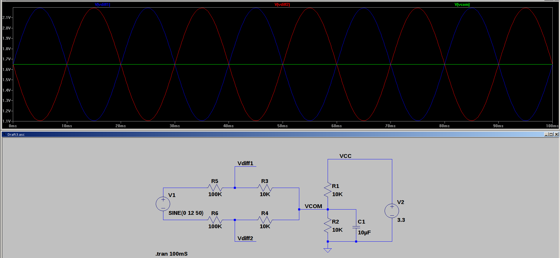
  •  Resistive divider can be similar to this one, dont decrease R5 R6 as they are setting the max current flowing on pin of (Edit DAC) ADC, better is add also two diode to ground to prevent exceed negative rail. I used a 12V generator you can double 10K resistor for 6V but I suppose dinamic can be enough. If not leave at almost some 30% margin to prevent damages. If current is forever low GPIO pin doesn't damage. (refer data sheet)

      Just for reference measure of ISOLATED mains at secondary of a low voltage transformer.

     DO NOT USE FOR MAINS MEASURE!!!! It can be adapted but an isolation amplifier is the best solution and this can be a reference too on primary side of isolation device.

     Edit: changed mistyped DAC instead of ADC, simulation source file can be added but is for a non TI program frontend of SPICE Thank CB1 tell me bout erroneous.

  • Very nice (caring/detailed) drawing Roberto - helpful to many. (you may wish to edit "DAC" to "ADC" {other vendor provides DAC - not landed here, yet...})