This thread has been locked.

If you have a related question, please click the "Ask a related question" button in the top right corner. The newly created question will be automatically linked to this question.

TM4C1294 and MCP23017 I2C Input Configured Interface

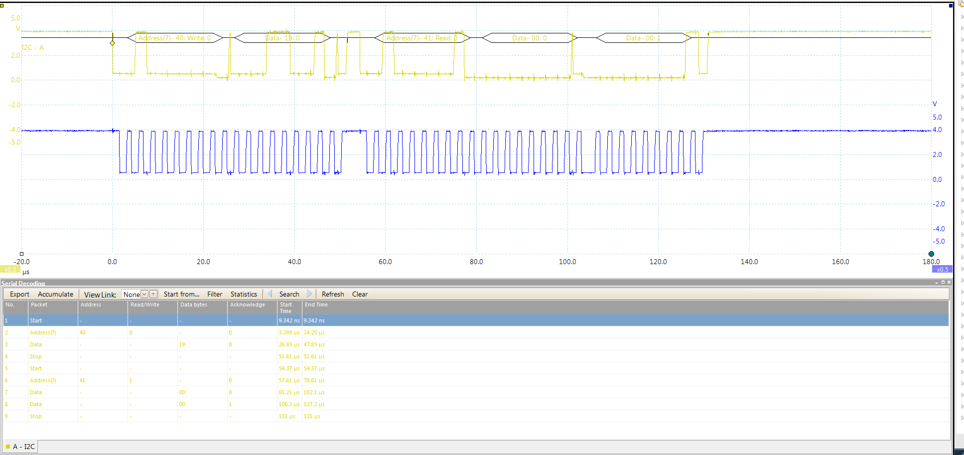
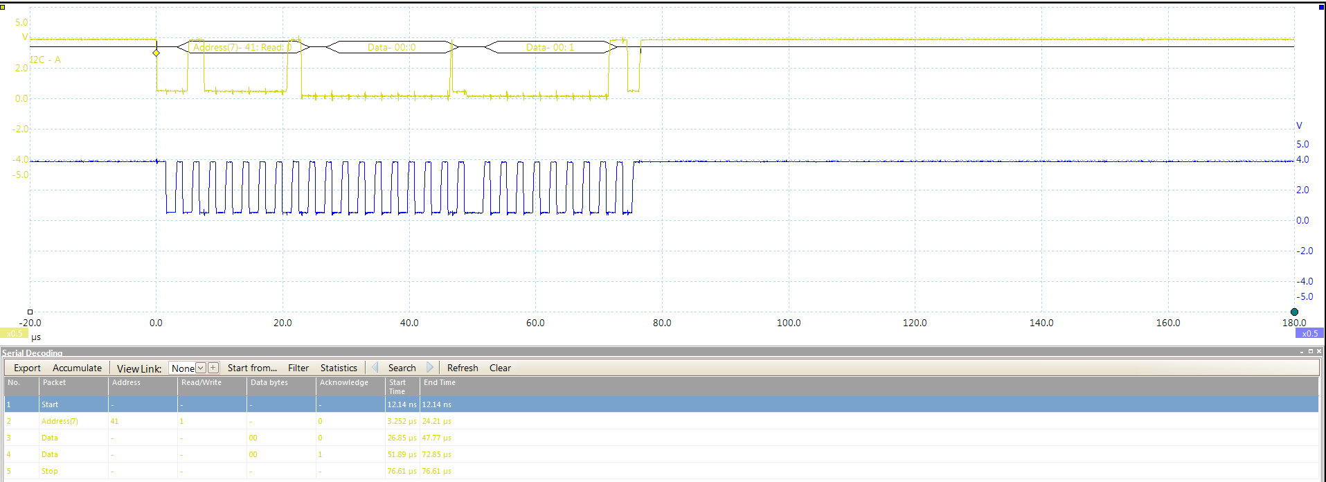
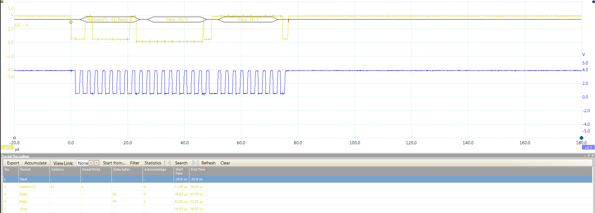
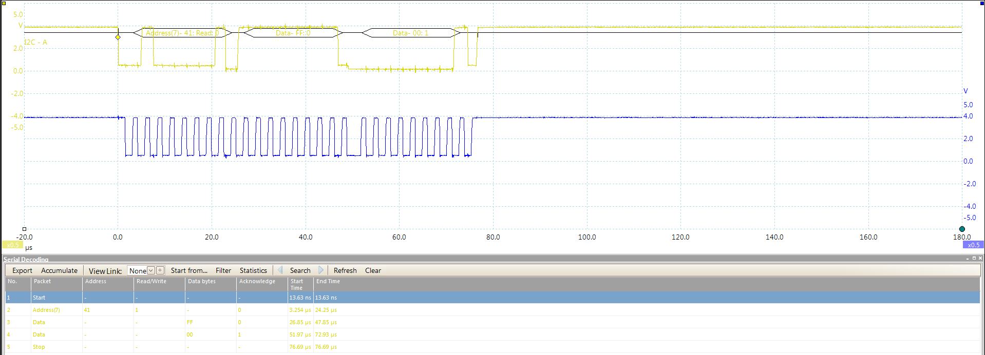
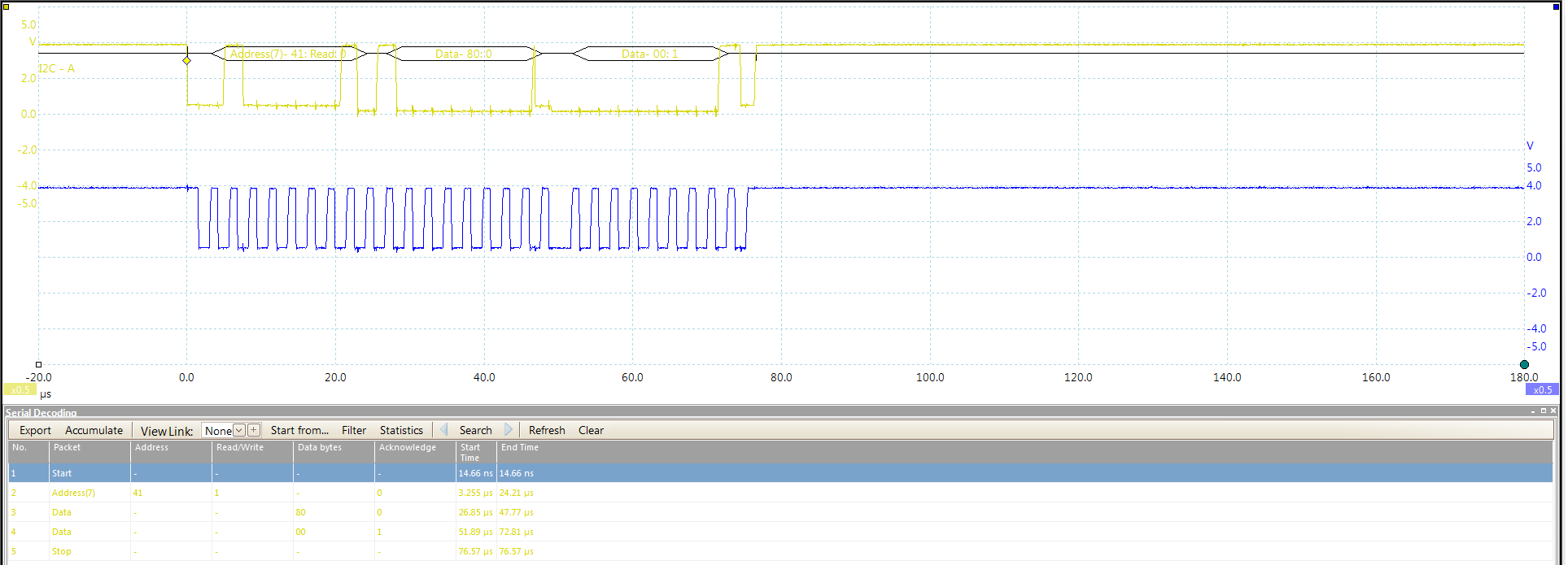
I am trying to interface a Tiva C TM4C1294 (master) with a MCP23017 I/O expander (slave) configured as input. However, I am not reading in the inputs that I want it to but instead I am seeing the following messages on the I2C bus which cycle through the following 5 states roughly 1 seconds apart with all inputs open.

I have copied and pasted my master receive code below. Please let me know what I am doing wrong.

//

// Specify slave address for recieve
//
I2CMasterSlaveAddrSet(I2C7_BASE, address, true);
//
// Initiate recieve of character from Slave to Master
//
I2CMasterControl(I2C7_BASE, I2C_MASTER_CMD_BURST_RECEIVE_START);
//
// Wait for recieve to begin
//
while(!I2CMasterBusy(I2C7_BASE));
//
// Delay until recieve completes
//
while(I2CMasterBusy(I2C7_BASE));
//
// Get the character that was recieved in the data register
//
data[0] = I2CMasterDataGet(I2C7_BASE);
//
// Initiate recieve of character from Slave to Master
//
I2CMasterControl(I2C7_BASE, I2C_MASTER_CMD_BURST_RECEIVE_FINISH);
//
// Wait for recieve to begin
//
while(!I2CMasterBusy(I2C7_BASE));
//
// Delay until recieve completes
//
while(I2CMasterBusy(I2C7_BASE));
//
// Get the character that was recieved in the data register
//
data[1] = I2CMasterDataGet(I2C7_BASE);

Thank you,

Andrew

  • Hello Andrew,

    For the data as seen on the Scope/LA are you getting the same in the data[0] and [1] buffers?

    Regards
    Amit
  • Yes, I am getting the same thing in the data[] buffer
  • Hello Andrew,

    So if the data on the scope shows 0x80 and 0x00 and so does the two buffer show 0x80 and 0x00 then isn't that OK?

    Regards
    Amit
  • No, because I am NOt toggling those inputs. The board is doing that on its own. I have no control of it and I don't know why it does it. The board toggles through all of those states (shown in the pictures above) every 5 seconds.
  • Hello Andrew,

    The code is addressing the Slave device with the correct address and the slave ACK's the address. After that the Slave will send the data to the Master as per the address in the slave address pointer register.

    Regards
    Amit
  • So what am I doing wrong in my code?
  • Hello Andrew,

    To read a location from the MCP slave device (at least what I could see from the MCP data sheet) is to first access the device in write mode with the address of the register and then perform a repeated start with a read to the device address and get the data from the address written previously.

    Regards
    Amit
  • Amit,

    I am trying to read from pin1 of the port B and this is how I have coded the program to read in the value of that pin. Does this look correct?

    UpdateSwitchState[0] = 0x19;

    // UpdateSwitchState[1] = 0x00;

    I2C7MasterTX(0x20, UpdateSwitchState, 1);

                                    |                   |                       |____ number of bytes I want to send

                                    |                   |___ data that I want to send to the device

                                    |___ Address of the device 0x40

    I2C7MasterRX(0x20, 2);

                                   |        |____ number of bytes I want to recieve

                                   |___ Address of the device 0x40

    STB1_state = data[0] & 0x00000001;

    I have attached a snapshot of the I2C bus below.

  • Hello Andrew,

    Yes, that looks "almost" correct except that there is a Stop and Start between the two transactions instead of a Repeated Start.

    Regards
    Amit
  • Amit,

    How do I generate a repeated start? Do I just use this command I2C_MASTER_CMD_BURST_SEND_START instead of I2C_MASTER_CMD_SINGLE_SEND?
  • Do follow Amit's lead - back around 2007 we used that exact I2C based I/O extender with great success. Note that "reading" is often much harder than "writing" to such a device.

    May I suggest that (temporarily) you switch to trying to write to that channel? An Led can serve as output monitor - and such will confirm that your interconnects are proper and that your I2C addresses are correct.

    Lastly - are proper/external pull-up R's emplaced - both SCL & SDA? Have you measured their resistance to 3V3?
  • I have written to this device while trying to trouble shoot the read protocol. I was able to successfully write to this device and get an output.

  • Andrew Butler said:
    I was able to successfully write to this device and get an output.

    That's of course highly useful info - confirms that your interconnect (MCU -> I/O Ext) and address scheme is correct.

    May I suggest that you attempt to read the 2nd port (assumes you've a 16 bit device) and/or a different bit - just in case.

    I'd suggest your use of a good pull-up (say 4K7) along with ground connection upon 2 I/O Ext pins configured as inputs - for testing.

    If you're still stuck tomorrow - I'll search for past code - might you confirm the exact part number of your device?

    Again - please do change to a different port and pins - it's entirely possible that single pin you're testing has "issues" - burns time/effort of all...

  • Hello Andrew

    Yes, that is correct. Instead of SINGLE_SEND it should be SEND_START.

    Regards
    Amit