This thread has been locked.

If you have a related question, please click the "Ask a related question" button in the top right corner. The newly created question will be automatically linked to this question.

TM4C123 Quadrature Encoder Interface (QEI)

Hi,

Is this viable to provide input to QEI from other input pulse source other than quadrature encoder?

I want to use two different pulses (3.3V) coming out from two proximity sensors, placed adjacent to each other to detect 4 nuts on wheel.

Is this possible to give these sensors output (3.3V pulse) to QEI of TM4C123 micro-controller to sense number of pulses as well as the reverse direction of wheel?

  • Hello Sayed

    It should be possible to do so. Can you show a diagram of how the pulses would be in time?

    Regards
    Amit
  • I tried but not succeeded, so i m sending you the screen shot of pulses on oscilloscope. yellow color pulse is consider as phase A & green color pulse is considered as phase B. Is the time delay between the pulses are good enough to detect the reverse movement. please help me out.

    regards

    Sayed

  • Sayed,

    Unfortunately your signal is not suitable as is. The QEI module will think that your encoder goes forward one tick, then backward one tick. Vice versa for the other channel. For the quadrature decoding to work, both the high and low "phases" of the signals need to overlap, and ideally the edges should be spread out evenly (the signals should have a phase difference of 90 degrees). See the following image for an example:

    -Veikko

  • Hello Sayed,

    Veikko is absolutely right. What you need to do is to use two timers to capture the time instant of edges and then subtract the lead from the lag edge

    Regards
    Amit
  • Hi,

    Thanks Veikko & Amit for worthy suggestions.

    Amit can you please elaborate it further. 

    Previously, I used Input capture to count the no. of pulses. Is there any probability that Input capture can also be used for detecting the reverse movement of the wheel?

    Regards

    Sayed

  • Hello Sayed

    What the application requires is the Input Edge Time Mode. In this mode the Timer counter runs continuously and when an edge occurs it snapshots the capture time and asserts an interrupt to the CPU. The application can then via an Interrupt Handler read the time at which the edge occurred.
    The important things to note are
    1. The two times being used must be started together (using sync feature of the timer)
    2. The Max time count bits are 24 (16 count + 8 prescalar). Hence when 24 bits roll over you need to ensure that any split time across the edges are not around the roll over. This can be done via a 3rd time that runs in periodic mode and indicates a timeout on roll over which can be used as a reference.

    Regards
    Amit
  • If the signal frequency is not high (say, under 10 kHz), the most flexible solution would probably be to use GPIO interrupts and then a software "decoder". You could have a persistent variable that remembers which line triggered last, and deduct the direction of rotation from that. But this comes with a big caveat:

    It doesn't really matter how you decode the signal, with that kind of a waveform you cannot reach a reliable scheme. Just think about it - if for some reason one pulse from either channel goes "missing in action", then the previously described scheme would interpret it as a direction change that would not remedy itself until the next glitch!

    Or consider the following: the rotation stops exactly where channel A is high. When rotation resumes, the next state change - regardless of direction - is that channel A goes low, then B goes high and so on. I could go on, but I hope you get the idea.

    There is a reason to why the quadrature encoders output the kind of signal they do :-)

  • What I'm really trying to say is that I think you should change the actual physical measurement of the signal to be "quadrature compatible".

    The obvious solution would of course be that you move the sensors closer together so that the "high sections" of the signals overlap by approx. 1/2 of their length.

    If this is not possible, you could move the other sensor to detect the next nut, and then position it so that the resulting waveform is the same as suggested above. Assuming that the nuts are evenly spaced, of course.

    Still one caveat: while you could track position & direction with this solution, your speed estimate would be "spiky" - you would get four "ticks" every time a nut goes by, then silence until the next nut comes about.

    If you don't need the resolution, though, you could alleviate this by reacting to just the rising edges on channel A (for example), then use the state of channel B to determine direction.
  • Might you be able to (almost) achieve (some) quadrature-like performance by having each sensor trigger a HW timer (a la 555) such that your signals achieve some of the (required) quadrature overlap?

    I've neither diagrammed - nor thought long/hard - but my sense is that two equal width timer outputs may approximate a legitimate quadrature waveform. (or not - if this HW addition does work you should be able to copy/model it w/in SW - as the other posters suggest)

    Sometimes HW proves fastest/easiest in "proving a concept" - HW in this case may enable your (desired) use of the MCU's QEI inputs...

    [edit]   After some thought/review - above proposal may work but only for a very limited range of input frequency.  (i.e. pulse width of timers must vary with the input frequency - adding great complications.)   Unknown is the sensitivity of vendor's QEI module to input signals where phase relationship differs from 90°.

  • thank you all for your suggestions & inputs!!
    Sorry I was outstaion on official duty so that I was not able to see your replies.

    I want to add one more thing that If wheel moves slowly the pulse-width will vary. This will add headache when we try to generate QEI signal.

    In this way, I think Amit's suggestion is viable but is complex. I need to sit with Amit to understand the concept.

    Amit, I am already using Edge capture with timer to count no. of pulses, but to get direction through this method I am finding it difficult.

    Will you please ease my situation if u send small bit of code to explain?

    That will help me to understand!!

    thanks again to all of you for your kind support!!
  • Hello Sayed,

    Since the signals are not in Quadrature the direction information is tough to extract. I would have to suggest converting it to Quadrature mode using GPIOs (instead of using timers).

    Basically when a rising edge occurs on one signal make a output GPIO High. On the next edge toggle it low. This way when both signals are taken into account, the ending result (though not exactly 90 degree out of phase) but would have sufficient overlap to be detected by the Quadrature module.

    Opinion sought-ed on the solutions from the forum.

    Regards
    Amit
  • Amit Ashara said:
    Opinion sought-ed

    Note that I'm more than a bit shy - yet as you asked...

    Have we not got 3 reasonably capable MCU guys here - trying to "reverse engineer" - a long proven, effective device (i.e. a real QEI encoder) - without any expression of the "real" need nor any justifications by the requester?    (other than his cost/effort saving...)

    Does this (really) make sense?

    QEI encoding exists for good reason - all of my attempts to discern speed/phase and (especially) direction - by other means - cannot compete!

    Saying NO to posters - "BAD Idea!" - may (sometimes) make sense!

  • cb1- said:
    Saying NO to posters - "BAD Idea!" - may (sometimes) make sense!

    Seconded. In a university environment I've said to younger "scientists" on multiple occasions quite directly that "You're Doing It Wrong!" and more often than not have had the same people come back with thanks for prodding in the right direction.

    About the case in hand - I would definitely tag it as "YDIW". Even cb1's ingenious idea of using timer chips to mutilate the original signal indeed only works on certain frequencies - there is no way to escape the fact that you need to fill the minimum requirements of quadrature signalling to "get it right".

    No matter how good the chef is, you can't expect haute cuisine if you give him/her c**p ingredients...

  • @Veikko,

    Well stated - 2 out of 3 "helpers" now lean toward, "Abandoning this sinking ship!"

    Appreciate your kind characterization of my "flawed" (works only over very small, controlled frequency range) swag.   Ingenuity - when desperate - too often reveals weakness when (really) probed.   (I was proud for several hours - and then, "Oh S*** !")   That said - "cb1 fan club" now (maybe) rises to two...  (take a number boyz...)

    Long live the real QEI encoding - as evidenced here - deservedly so.

    Sadly I see no real value in Amit's - equally desperate - toggle on then off - on each/every signal arrival.   In this case - QEI clearly rules...

  • Hello Veikko, cb1

    May be the disclaimer was not strong enough

    Amit Ashara said:
    Since the signals are not in Quadrature the direction information is tough to extract

    But then that is the poster to evaluate as well, before they go into a change of design to true-QEI

    Regards

    Amit

  • A few notes.

    Agree that a true quadrature signal is to be much preferred.

    This arrangement is similar to that used on some PMAC/BLDC motors. The common solution when they cannot place the sensors close enough to get a quadrature signal from a single mounting point is to use two mounting points The second sensor is mounted so that it detects a different nut (presumably there are several so your 'gear' stay balanced). By varying the position of the second sensor for this second nut you can easily generate a quadrature signal.  There are app notes around showing this usage on gear teeth with proximity sensors IIRC.

    You could also form a ring with alternating high lows sections in an ~50% duty cycle fastened to your nuts to produce a better waveform for quadrature, your signal duty cycle really should be increased.

    An advantage to quadrature encoding over the arrangement you have now is that it allows a form of noise filtering otherwise not available.  There are two issues where edge noise shows up.  One is the transition from on to off and vice versa may have noise. Good implementations will have enough hysteresis to reduce this. The second occurs when the rotation has stopped. If one of the sensors is sitting on an edge then it can jitter back and forth on the edge producing many transitions without moving. This occurs surprisingly easily and worse can have nearly any frequency so it is not easy to filter. Both of these can be eliminated with an A clock B, B clock A filter (you produce and A' signal by setting it to the level of A whenever B makes a transition and similarly for B', these A' and B' are fed to the quadrature rather than A and B).  The issue with this filter is you lose transitions when changing direction.

    Robert

  • Robert Adsett said:
    The common solution when they cannot place the sensors close enough to get a quadrature signal from a single mounting point is to use two mounting points The second sensor is mounted so that it detects a different nut (presumably there are several so your 'gear' stay balanced). By varying the position of the second sensor for this second nut you can easily generate a quadrature signal.

    Exactly what I was trying to say on the first page, but you said it better! Vote #2 for this solution. In any case, I think reaching a reasonable result requires changing the physical arrangement.

  • May I respectfully note that after all the special effort - and thought - and different part/device procurement - a "real" QEI encoder remains vastly superior! And - very likely costs far less than the special parts & fittings & (endless) test/verify to design/develop a "solid" experimental prototype.

    Firm CUI produces a very nice - reasonably low cost, quadrature encoder "AMT103-V" which sells for ~20 (USD) at 100 pc quantities. (~24 USD @ 1 pc) This device provides phases A, B and an index - adapts easily to multiple shaft sizes - and comes encased in a shielded, metal enclosure. In stock @ DigiKey. 

    Our firm has used this for past year + we're pleased with the results.   (yet receive "no" benefits from this "vote of confidence."   Unfortunate that...)
     
    There's a chip version of this QEI device - saves size/cost - but involves similar design/development effort to the experimental method - just suggested.

    Long live QEI - let this serve as votes 8,9, 10 for a "real & proper" encoder...   (we in Chicago vote early... and often...some even from the grave...)

  • Hello Robert, Veikko

    Robert Adsett said:
    The second sensor is mounted so that it detects a different nut (presumably there are several so your 'gear' stay balanced). By varying the position of the second sensor for this second nut you can easily generate a quadrature signal.

    Not quite sure on this implementation. Illustration if possible since I can't get a visual picture of the assembly and quadrature signals?

    Regards

    Amit

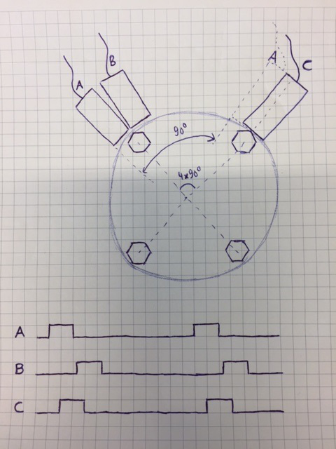
  • Here's my attempt to illustrate:

    Note the "ghost" A sensor at a 90 degree offset. Of course the scheme can be applied to other bolt/nut patterns as well. As I said before, this will produce a jumpy/spiky speed signal as you will see 4 transitions in short succession, then silence until the next nut comes by.

    @cb1, absolutely - if a commercial sensor can be mounted then there's no reason to "make your own" - an off-the-shelf sensor will most always be cheaper all things considered. But if you don't have access to the center of the shaft, for example, then mounting a standard sensor might be a pain. For what it's worth, I've used CUI's 203 line (which I believe is very similar to the 103) and found it very nice - but it needs a good mounting location as it doesn't have any internal bearing of it's own. Sticking one at the rear end of a motor is cakewalk, though - that's where they shine. The original poster didn't reveal enough information about his setup to determine whether a commercial sensor could be mounted with ease, but if yes - then all this discussion is indeed moot.

    (Just realized that this thread has also gone very much beyond just TM4C...)

  • Veikko Immonen said:
    Just realized that this thread has also gone very much beyond just TM4C...)

    Mais certainement - mon ami - very much indeed.    Might that be because the original thrust was tres "boring" - and expecting/demanding (100% code delivered s'il vous plait - maintenant!)

    Good to know that you've experience w/similar sensor - your description of, "when/where/how" superb!

    And the (long) needed - descriptive drawing - arrives from you!   (not o.p.)  Thus - when a thread is becalmed (starved for relevant information) is it not "fair game" for those w/(some) skill/background to "jump in?"  Might our "saving" Amit from "defocus from TM4C" (somewhat) justify our shape shifting?   (how tortured that logic...)

    Might someone - somewhere - give poster his (long) requested example code?   (cb1 departs)

  • Hello Veikko

    Thanks a lot. Now that explains the solution very well and clarifies my doubts too.

    My 2 cents: TM4C is a tool to implement (could have been any other uC as well). The neat trick lies outside of the 10mmx10mm plastic.

    Regards
    Amit
  • Veikko Immonen said:
    Here's my attempt to illustrate:

    Nice illustration.

    I went looking for some application notes to see if I could find one on using gear tooth sensors.  I didn't find that but I did find this

    www.allegromicro.com/~/media/Files/Technical-Documents/AN27701-Hall-Effect-IC-Application-Guide.ashx 

    Fig 27 is an interesting alternative

    Also

    http://www.allegromicro.com/en/Design-Center/Technical-Documents/Hall-Effect-Sensor-IC-Publications/Ring-Magnet-Speed-Sensing-For-Electronic-Power-Steering.aspx

    Illustrates the technique

    Robert

  • Amit Ashara said:
    The neat trick lies outside of the 10mmx10mm plastic.

    I often find that to be the case

    Robert

  • Veikko Immonen said:
    Here's my attempt to illustrate:


    Nice illustration.


    I went looking for some application notes to see if I could find one on using gear tooth sensors. I didn't find that but I did find this


    www.allegromicro.com/~/media/Files/Technical-Documents/AN27701-Hall-Effect-IC-Application-Guide.ashx


    Fig 27 is an interesting alternative


    Also


    www.allegromicro.com/.../Ring-Magnet-Speed-Sensing-For-Electronic-Power-Steering.aspx


    Illustrates the technique


    Robert
  • HI,
    kindly receive my deep hearted thanks for contributing in this discussion.
    All this inputs will really help me in my new design.
    I also like to appreciate the time & effort given by Veikko for providing drawing of sensors position.

    regards
    Sayed Tausif
  • sayed tausif said:
    All these inputs will really help me in my new design.

    Good (and proper) that you thanked your responders - especially Veikko's time/effort in creating his clear diagram.

    Yet - unless this is a, "School project" - your time & effort in, "Recreating the wheel" (i.e. QEI encode device) still seems unlikely to equal that "standard" and will eat your time/effort/funds.  

    We note that the "motivation" for such (duplicative yet unequal) design effort remains unexplained...