Hi!
The problem:
In the code spi_master.c, characters are printed to the serial console window. Line 167 in the code is shown, line 168 is not shown. With these settings:
//
// Initialize the UART for console I/O.
//
UARTStdioConfig(0, 115200, 16000000); 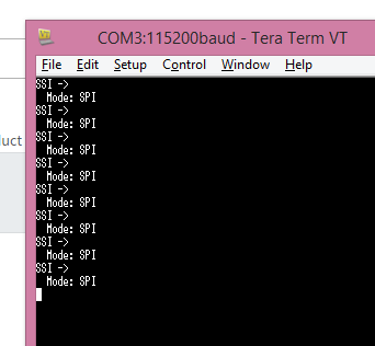
The console is also setup for 115200 bits/s.
Switching baud-rate, what happens? Its very strange that it cuts straight into a sentence.
What would possible cause this line: UARTprintf(" Data: 8-bit\n\n");
to not write the " a: 8-bit" ?

Pushing the resetbutton on launchpad, makes the same message appear after each "reset".
Talking with Putty instead?

My friend can run the code on a linux dist, using screen as serial console. Everything works fine. what is this sorcery?
Serial console programs: Putty and Tera term, both show the same error. Using standard: 8 bit data, 0 parity and 1 stop bit.
Platform: TM4C123GXL Launchpad, tiva c series
Program: Code Composer Studio, Version: 5.5.0.00077
Code:
C:\ti\TivaWare_C_Series-2.1.0.12573\examples\peripherals\ssi using the given example; spi_master.c
//*****************************************************************************
//
// spi_master.c - Example demonstrating how to configure SSI0 in SPI master
//                mode.
//
// Copyright (c) 2010-2014 Texas Instruments Incorporated.  All rights reserved.
// Software License Agreement
//
//   Redistribution and use in source and binary forms, with or without
//   modification, are permitted provided that the following conditions
//   are met:
//
//   Redistributions of source code must retain the above copyright
//   notice, this list of conditions and the following disclaimer.
//
//   Redistributions in binary form must reproduce the above copyright
//   notice, this list of conditions and the following disclaimer in the
//   documentation and/or other materials provided with the
//   distribution.
//
//   Neither the name of Texas Instruments Incorporated nor the names of
//   its contributors may be used to endorse or promote products derived
//   from this software without specific prior written permission.
//
// THIS SOFTWARE IS PROVIDED BY THE COPYRIGHT HOLDERS AND CONTRIBUTORS
// "AS IS" AND ANY EXPRESS OR IMPLIED WARRANTIES, INCLUDING, BUT NOT
// LIMITED TO, THE IMPLIED WARRANTIES OF MERCHANTABILITY AND FITNESS FOR
// A PARTICULAR PURPOSE ARE DISCLAIMED. IN NO EVENT SHALL THE COPYRIGHT
// OWNER OR CONTRIBUTORS BE LIABLE FOR ANY DIRECT, INDIRECT, INCIDENTAL,
// SPECIAL, EXEMPLARY, OR CONSEQUENTIAL DAMAGES (INCLUDING, BUT NOT
// LIMITED TO, PROCUREMENT OF SUBSTITUTE GOODS OR SERVICES; LOSS OF USE,
// DATA, OR PROFITS; OR BUSINESS INTERRUPTION) HOWEVER CAUSED AND ON ANY
// THEORY OF LIABILITY, WHETHER IN CONTRACT, STRICT LIABILITY, OR TORT
// (INCLUDING NEGLIGENCE OR OTHERWISE) ARISING IN ANY WAY OUT OF THE USE
// OF THIS SOFTWARE, EVEN IF ADVISED OF THE POSSIBILITY OF SUCH DAMAGE.
//
// This is part of revision 2.1.0.12573 of the Tiva Firmware Development Package.
//
//*****************************************************************************

#include <stdbool.h>
#include <stdint.h>
#include "inc/hw_memmap.h"
#include "driverlib/gpio.h"
#include "driverlib/pin_map.h"
#include "driverlib/ssi.h"
#include "driverlib/sysctl.h"
#include "driverlib/uart.h"
#include "utils/uartstdio.h"

//*****************************************************************************
//
//! \addtogroup ssi_examples_list
//! <h1>SPI Master (spi_master)</h1>
//!
//! This example shows how to configure the SSI0 as SPI Master.  The code will
//! send three characters on the master Tx then polls the receive FIFO until
//! 3 characters are received on the master Rx.
//!
//! This example uses the following peripherals and I/O signals.  You must
//! review these and change as needed for your own board:
//! - SSI0 peripheral
//! - GPIO Port A peripheral (for SSI0 pins)
//! - SSI0Clk - PA2
//! - SSI0Fss - PA3
//! - SSI0Rx  - PA4
//! - SSI0Tx  - PA5
//!
//! The following UART signals are configured only for displaying console
//! messages for this example.  These are not required for operation of SSI0.
//! - UART0 peripheral
//! - GPIO Port A peripheral (for UART0 pins)
//! - UART0RX - PA0
//! - UART0TX - PA1
//!
//! This example uses the following interrupt handlers.  To use this example
//! in your own application you must add these interrupt handlers to your
//! vector table.
//! - None.
//
//*****************************************************************************

//*****************************************************************************
//
// Number of bytes to send and receive.
//
//*****************************************************************************
#define NUM_SSI_DATA            3

//*****************************************************************************
//
// This function sets up UART0 to be used for a console to display information
// as the example is running.
//
//*****************************************************************************
void
InitConsole(void)
{
    //
    // Enable GPIO port A which is used for UART0 pins.
    // TODO: change this to whichever GPIO port you are using.
    //
    SysCtlPeripheralEnable(SYSCTL_PERIPH_GPIOA);

    //
    // Configure the pin muxing for UART0 functions on port A0 and A1.
    // This step is not necessary if your part does not support pin muxing.
    // TODO: change this to select the port/pin you are using.
    //
    GPIOPinConfigure(GPIO_PA0_U0RX);
    GPIOPinConfigure(GPIO_PA1_U0TX);

    //
    // Enable UART0 so that we can configure the clock.
    //
    SysCtlPeripheralEnable(SYSCTL_PERIPH_UART0);

    //
    // Use the internal 16MHz oscillator as the UART clock source.
    //
    UARTClockSourceSet(UART0_BASE, UART_CLOCK_PIOSC);

    //
    // Select the alternate (UART) function for these pins.
    // TODO: change this to select the port/pin you are using.
    //
    GPIOPinTypeUART(GPIO_PORTA_BASE, GPIO_PIN_0 | GPIO_PIN_1);

    //
    // Initialize the UART for console I/O.
    //
    UARTStdioConfig(0, 115200, 16000000);
}

//*****************************************************************************
//
// Configure SSI0 in master Freescale (SPI) mode.  This example will send out
// 3 bytes of data, then wait for 3 bytes of data to come in.  This will all be
// done using the polling method.
//
//*****************************************************************************
int
main(void)
{
    uint32_t pui32DataTx[NUM_SSI_DATA];
    uint32_t pui32DataRx[NUM_SSI_DATA];
    uint32_t ui32Index;

    //
    // Set the clocking to run directly from the external crystal/oscillator.
    // TODO: The SYSCTL_XTAL_ value must be changed to match the value of the
    // crystal on your board.
    //
    SysCtlClockSet(SYSCTL_SYSDIV_1 | SYSCTL_USE_OSC | SYSCTL_OSC_MAIN |
                   SYSCTL_XTAL_16MHZ);

    //
    // Set up the serial console to use for displaying messages.  This is
    // just for this example program and is not needed for SSI operation.
    //
    InitConsole();

    //
    // Display the setup on the console.
    //
    UARTprintf("SSI ->\n");
    UARTprintf("  Mode: SPI\n");
    UARTprintf("  Data: 8-bit\n\n");

    //
    // The SSI0 peripheral must be enabled for use.
    //
    SysCtlPeripheralEnable(SYSCTL_PERIPH_SSI0);

    //
    // For this example SSI0 is used with PortA[5:2].  The actual port and pins
    // used may be different on your part, consult the data sheet for more
    // information.  GPIO port A needs to be enabled so these pins can be used.
    // TODO: change this to whichever GPIO port you are using.
    //
    SysCtlPeripheralEnable(SYSCTL_PERIPH_GPIOA);

    //
    // Configure the pin muxing for SSI0 functions on port A2, A3, A4, and A5.
    // This step is not necessary if your part does not support pin muxing.
    // TODO: change this to select the port/pin you are using.
    //
    GPIOPinConfigure(GPIO_PA2_SSI0CLK);
    GPIOPinConfigure(GPIO_PA3_SSI0FSS);
    GPIOPinConfigure(GPIO_PA4_SSI0RX);
    GPIOPinConfigure(GPIO_PA5_SSI0TX);

    //
    // Configure the GPIO settings for the SSI pins.  This function also gives
    // control of these pins to the SSI hardware.  Consult the data sheet to
    // see which functions are allocated per pin.
    // The pins are assigned as follows:
    //      PA5 - SSI0Tx
    //      PA4 - SSI0Rx
    //      PA3 - SSI0Fss
    //      PA2 - SSI0CLK
    // TODO: change this to select the port/pin you are using.
    //
    GPIOPinTypeSSI(GPIO_PORTA_BASE, GPIO_PIN_5 | GPIO_PIN_4 | GPIO_PIN_3 |
                   GPIO_PIN_2);

    //
    // Configure and enable the SSI port for SPI master mode.  Use SSI0,
    // system clock supply, idle clock level low and active low clock in
    // freescale SPI mode, master mode, 1MHz SSI frequency, and 8-bit data.
    // For SPI mode, you can set the polarity of the SSI clock when the SSI
    // unit is idle.  You can also configure what clock edge you want to
    // capture data on.  Please reference the datasheet for more information on
    // the different SPI modes.
    //
    SSIConfigSetExpClk(SSI0_BASE, SysCtlClockGet(), SSI_FRF_MOTO_MODE_0,
                       SSI_MODE_MASTER, 1000000, 8);

    //
    // Enable the SSI0 module.
    //
    SSIEnable(SSI0_BASE);

    //
    // Read any residual data from the SSI port.  This makes sure the receive
    // FIFOs are empty, so we don't read any unwanted junk.  This is done here
    // because the SPI SSI mode is full-duplex, which allows you to send and
    // receive at the same time.  The SSIDataGetNonBlocking function returns
    // "true" when data was returned, and "false" when no data was returned.
    // The "non-blocking" function checks if there is any data in the receive
    // FIFO and does not "hang" if there isn't.
    //
    while(SSIDataGetNonBlocking(SSI0_BASE, &pui32DataRx[0]))
    {
    }

    //
    // Initialize the data to send.
    //
    pui32DataTx[0] = 's';
    pui32DataTx[1] = 'p';
    pui32DataTx[2] = 'i';

    //
    // Display indication that the SSI is transmitting data.
    //
    UARTprintf("Sent:\n  ");

    //
    // Send 3 bytes of data.
    //
    for(ui32Index = 0; ui32Index < NUM_SSI_DATA; ui32Index++)
    {
        //
        // Display the data that SSI is transferring.
        //
        UARTprintf("'%c' ", pui32DataTx[ui32Index]);

        //
        // Send the data using the "blocking" put function.  This function
        // will wait until there is room in the send FIFO before returning.
        // This allows you to assure that all the data you send makes it into
        // the send FIFO.
        //
        SSIDataPut(SSI0_BASE, pui32DataTx[ui32Index]);
    }

    //
    // Wait until SSI0 is done transferring all the data in the transmit FIFO.
    //
    while(SSIBusy(SSI0_BASE))
    {
    }

    //
    // Display indication that the SSI is receiving data.
    //
    UARTprintf("\nReceived:\n  ");

    //
    // Receive 3 bytes of data.
    //
    for(ui32Index = 0; ui32Index < NUM_SSI_DATA; ui32Index++)
    {
        //
        // Receive the data using the "blocking" Get function. This function
        // will wait until there is data in the receive FIFO before returning.
        //
        SSIDataGet(SSI0_BASE, &pui32DataRx[ui32Index]);

        //
        // Since we are using 8-bit data, mask off the MSB.
        //
        pui32DataRx[ui32Index] &= 0x00FF;

        //
        // Display the data that SSI0 received.
        //
        UARTprintf("'%c' ", pui32DataRx[ui32Index]);
    }

    //
    // Return no errors
    //
    return(0);
}