


Other Parts Discussed in Thread: TM4C129XNCZAD
Hi,
After developing some applications for the development kit I am now designing a custom PCB to mount the TM4C129XNCZAD processor and a capacitive touch screen. Looking at the schematics of the development kit screen connection, the data lines are connected in a strange way.
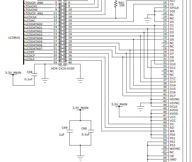
The PS0-3 lines select 8-bit 8080 parallel interface, D[8:1] (from - http://www.utasker.com/Shop/FS-K350QVG-V2-F-01.pdf )
However lines D[8:1] are also connected to D[16:9].
Looking through the screen and the driver datasheets. ( http://www.crystalfontz.com/controllers/SSD2119.pdf )
I can't seem to find this explained.
It looks like the 8 bit data D[8:1] should be decoded by the screen IC and image formed.
Does anyone know what the additional D[16:9] lines are used for (they have the same data connected).
